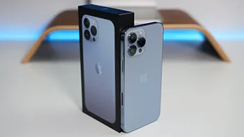
The iPhone 13 Pro Max has taken the mobile world by storm, offering blazing 5G performance and a stunning 120Hz screen refresh.
This powerhouse of a phone not only delivers top-tier performance but also comes with a host of features and tips to help you make the most of it.
In this guide, we’ll share some essential tips and tricks to unlock the full potential of your iPhone 13 Pro Max.
Mastering the Side Buttons
With the absence of the HOME button, the iPhone 13 lineup introduces new shortcuts.
Understanding these button combinations can significantly enhance your user experience:
Summoning Siri: Long-pressing the side keys activates Siri, your digital assistant. This is a great way to get things done quickly.
Taking Screenshots: To capture your screen, simultaneously press the side key and the volume up button. It’s a breeze to share what’s on your screen.
Emergency Features: In the powered-on state, long-press the volume up/down keys along with the side key to access important features like the medical emergency card and SOS emergency contacts. In shutdown, perform the same action to power on your device.
Lock Screen Shortcuts
On the lock screen interface of your iPhone 13 Pro Max, you’ll find two handy shortcuts for the camera and flashlight. Here’s how to use them:
Camera Shortcut: Gently press the camera icon on the lock screen. You’ll feel a vibration feedback, and the camera app will quickly launch.
Flashlight Shortcut: Similarly, pressing the flashlight icon will instantly turn on the flashlight. These shortcuts provide quick access to essential functions.
If you prefer a different approach, you can still use the classic swipe gestures. Swipe to the left to open the camera interface and swipe to the right for the control center.
Night time Accessibility
For night owls who love using their phones in low-light conditions, the iPhone 13 Pro Max offers an excellent feature: automatic brightness adjustment.
However, sometimes, it might not be enough. Here’s a tip for enhancing your nighttime experience:
Reducing White Point: Navigate to your phone’s settings and choose the ‘Accessibility’ section. Set the auxiliary function shortcut key to reduce the white point value. When in a dimly lit environment, simply press all three side keys simultaneously to activate this feature, reducing the white point value and making the screen gentler on your eyes.
By following these tips and tricks, you can truly make the most of your iPhone 13 Pro Max.
Whether you’re navigating the new button combinations, using convenient lock screen shortcuts, or enhancing your nighttime experience, these insights will help you harness the full potential of your powerful device.
Enjoy your iPhone 13 Pro Max to the fullest, and make it work for you!
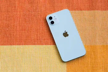
Having trouble signing in to your Apple ID on your new iPhone 12? Don’t worry, you’re not alone. This guide will provide you with practical solutions to resolve Apple ID sign-in issues on your iPhone 12. Whether it’s a network problem, forgotten password, or system error, we’ve got you covered. Follow these troubleshooting steps to regain access to your Apple ID and enjoy all the features and services it offers.
Network Issues
Restart your device: A simple restart can often fix temporary network glitches that might prevent you from signing in.
Check Apple System Status: Visit the Apple System Status page to ensure that the Apple ID service in your country or region is not experiencing any interruptions.
Change network environment: If possible, switch from Wi-Fi to cellular data or vice versa, and attempt to sign in again. Sometimes, network inconsistencies can hinder the sign-in process.
Reset network settings: If changing the network doesn’t help, you can reset your network settings by navigating to “Settings” > “General” > “Reset” > “Reset Network Settings.” Note that this action will erase stored network settings but won’t affect your data.
Apple ID Deactivation or Forgotten Password
Reset your password: If you or someone else entered your password incorrectly multiple times, your Apple ID might be disabled for security reasons. Visit the Apple ID Account Management page to reset your password and regain access to your account.
Apple ID locked for security reasons: If you see messages like “For safety reasons, this Apple ID has been disabled” or “You can’t sign in because your account has been disabled for security reasons,” follow the steps provided on the Apple ID Account Management page to unlock your account.
System Error
Back up important data: Before attempting any system-related fixes, it’s crucial to back up your important data to ensure its safety.
Update your device: Check for the latest iOS updates by going to “Settings” > “General” > “Software Update.” Install any available updates as they often include bug fixes and improvements that can resolve system-related issues.
Sign in after updating: Once your device is up to date, try signing in to your Apple ID again. The updated software might fix any glitches or errors encountered during the sign-in process.
Conclusion:
Don’t let Apple ID sign-in issues hinder your experience with your new iPhone 12. By following the troubleshooting steps outlined in this guide, you should be able to resolve network-related problems, recover your account if it’s been disabled or locked, and address system errors. Remember to keep your device updated to ensure optimal performance and security. Enjoy seamless access to your Apple ID and all the services it offers.
Face ID is a face-to-face ID, a face recognition system for Apple’s design and release, is first used in iPhone X; it allows users to unlock Apple devices, purchase in each Apple Digital Media Store, and as Apple Pay or Applications The authentication method pays within.
Apple’s Security Commitment
Apple boasts that Face ID offers a one-in-a-million chance of being unlocked by an unauthorized user. Face ID stands apart is its approach to data security. Unlike some systems that store sensitive data in the cloud, Apple’s Face ID stores your facial recognition information in a secure enclave within the Apple A11 Bionic chip. This ensures that your personal data remains on your device and in the cloud.
Compatible devices
Initially introduced with the iPhone X, Face ID has been part of various Apple devices, including:
iPhone X, Xʀ, Xs/Max, 11, 11 Pro/Max, 12/Mini, and 12 Pro/Pro Max
iPad Pro (third and fourth generation)
How Face ID Works
Face ID relies on a multi-step process to accurately identify the user:
Illumination and Infrared Imaging: Face ID first illuminates the user’s face with infrared light and captures a 2D infrared image using a floodlight sensor.
Infrared Camera Recognition: An infrared camera then scans the user’s face to capture distinct features.
Dot Array Projection: Over 30,000 unique encoded infrared points are projected onto the user’s face. These points reflect back to the infrared camera, creating a 3D map of the face’s surface.
Data Processing: The offset between the original infrared image and the reflected infrared points is analyzed, constructing a precise 3D model of the user’s face.
Mathematical Transformation: The infrared image and the 3D model are sent to the device’s processor, where they are transformed into a mathematical expression.
Face Comparison: The device compares the mathematical expression with previously registered facial data, determining whether to grant access.
Additional features
Face ID incorporates several features to enhance security and accuracy:
Floodlight: Invisible infrared light aids face identification, even in low-light conditions. This ensures that the system can discern if the user’s eyes are open and facing the device.
Dot Matrix Projector: More than 30,000 invisible dots are projected onto the user’s face to construct an accurate, 3D facial model. The arrangement of these dots is distinct for each individual.
Infrared Camera: This camera captures a 2D infrared image while reading the unique dot matrix pattern. The data is then analyzed and sent to the secure enclave within the A11 Bionic chip for comparison.
Technical Provider: Face ID incorporates technology from Sensomotoric INSTRUMENTS, utilizing PrimeSense Structural Light Technology and Faceshift for facial capture technology.
Conclusion
Apple’s Face ID is not just a convenient way to unlock your device; it’s a sophisticated and highly secure facial recognition system that leverages cutting-edge technology to ensure your privacy and security. With features like floodlighting, dot matrix projection, and infrared imaging, it’s no wonder that Face ID has become a benchmark for secure biometric authentication in the tech world. As Apple continues to innovate, we can expect even more exciting developments in this space.
Recently, many repair technicians reported that they had received lots of iPhone 11 Pro Max with no service.
Worse still, the fault could not be eliminated after replacing the signal board.
Based on experience, REWA LAB technicians preliminarily conclude that the fault is likely on the signal pads of the logic board. Let’s check it out!
Step 1: Fault analysis
The motherboard has been repaired once.
The original fault was no service but with the baseband modem firmware.
The previous repair welded the baseband CPU and baseband EPROM to a good signal board.
But the phone still had no service. It can be preliminarily judged that there are two possible faults.
One is the damage of baseband CPU and baseband EPROM.
The other is the damage of circuits related to the signal on the logic board.
First of all, we install the motherboard on the phone to test.
The phone turns on normally but has no service.
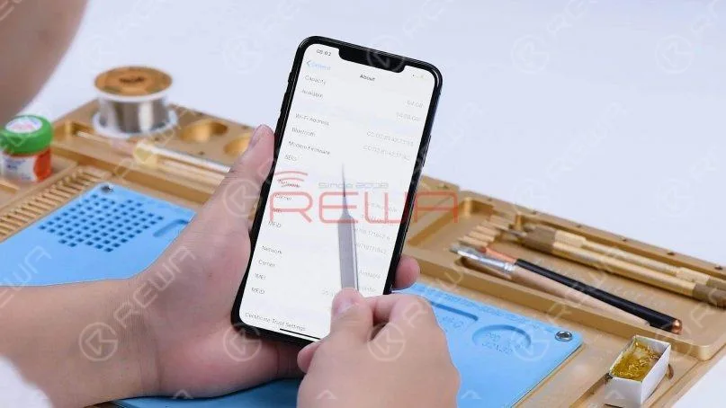
Go to Settings, General, and About. We can see that the phone has no modem firmware.
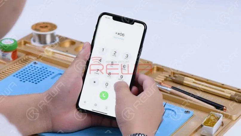
Dial *#06# and the IMEI can’t be seen.
The phone used to have modem firmware but now no longer has it. The cause may be related to pseudo soldering of the motherboard middle layer or damage of the baseband CPU and baseband EPROM.
Step 2: Motherboard separation and troubleshooting
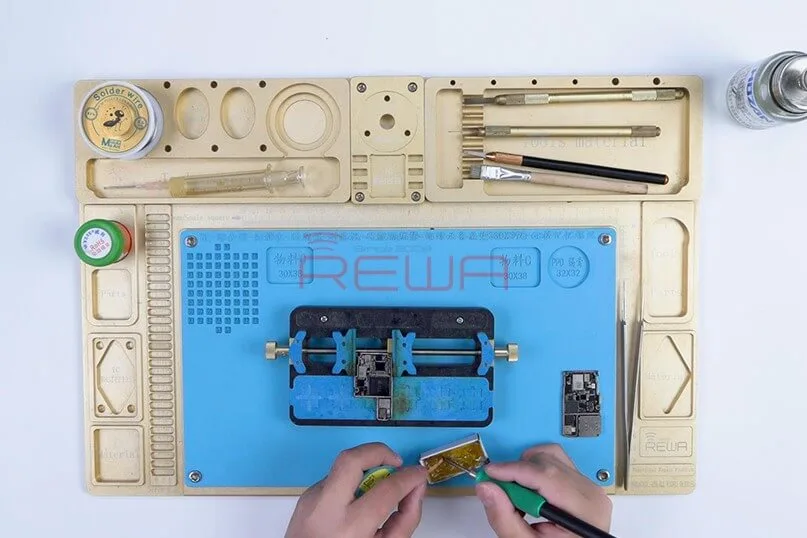
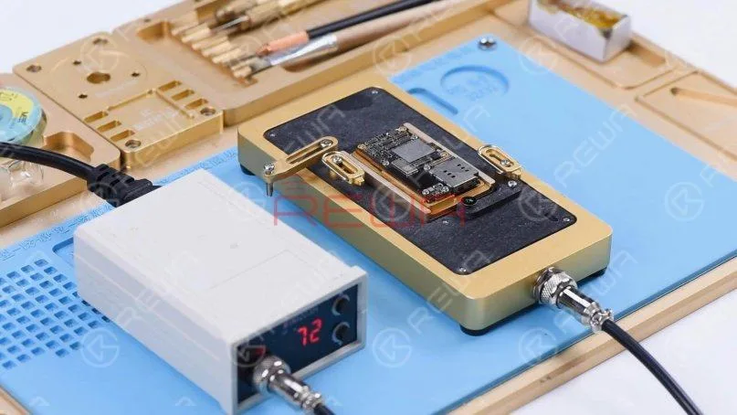
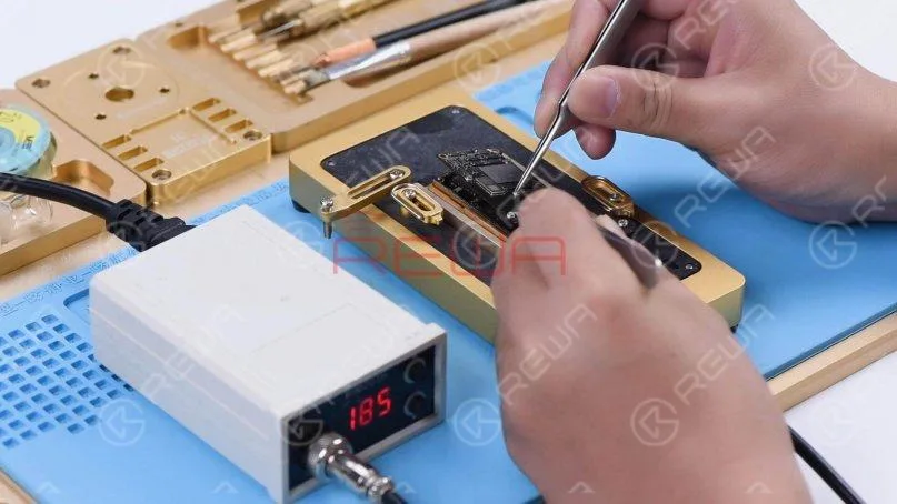
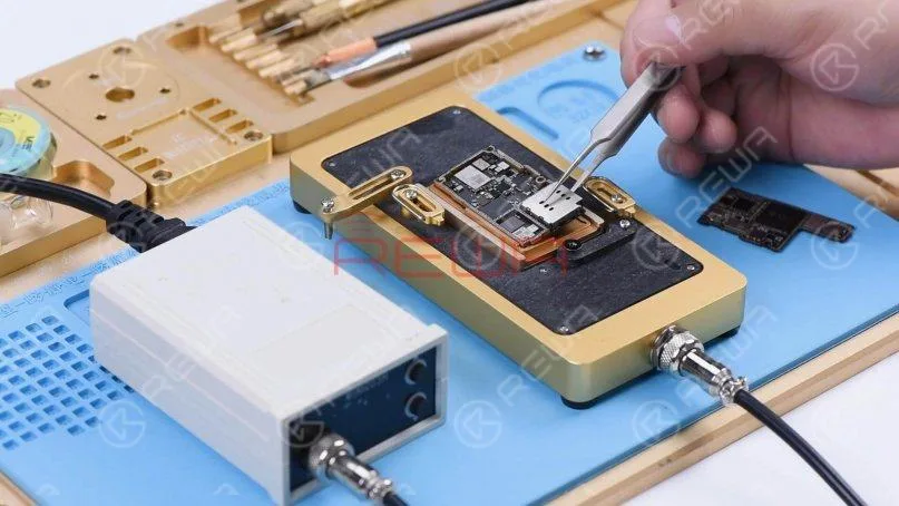
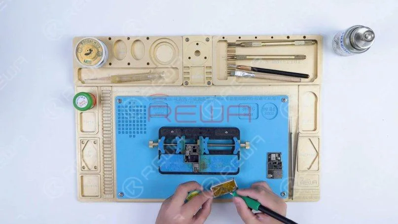
Then we separate the motherboard to locate the faulty component. Put the motherboard on the Heating Platform and set the temperature to 185℃.
When the temperature has risen to 185℃, remove the logic board with tweezers.
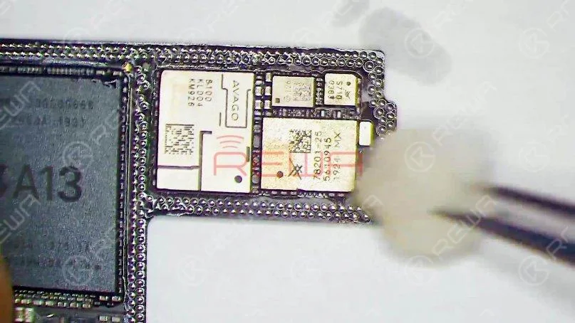
Turn the power off and remove the signal board.
Clean the logic board with PCB Cleaner.
Since the signal board has been replaced, we need to check the logic board first.
According to the test result, we can later determine whether the baseband CPU and EPROM are damaged.
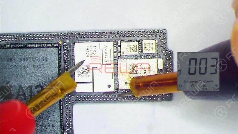
Run diode mode measurement of the signal pads on the middle layer of the logic board.
When measuring pin 131, the diode value is 003. The normal value should be around 400.
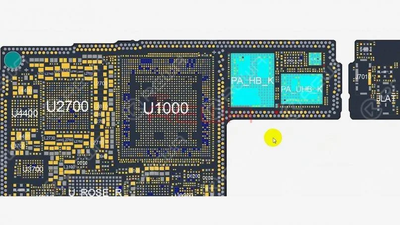
Open the bitmap and many associated components are seen on the circuit.
Then we locate the faulty component with rosin detecting.
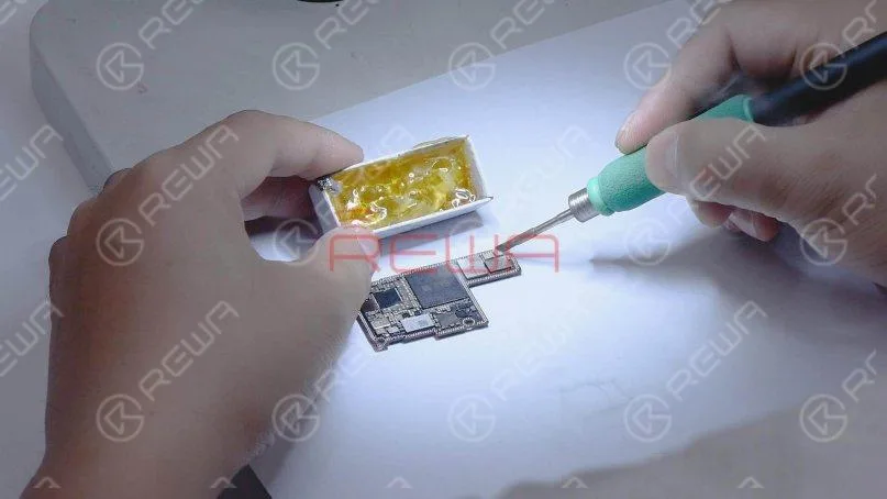
Dip rosin with Soldering Iron at 365℃ and smoke some rosin on associated components.
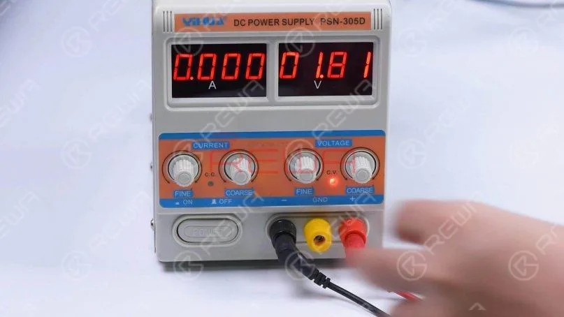
Set the direct current supply to 1.8V. Connect the positive and negative anode of the direct current supply with multimeter probes.
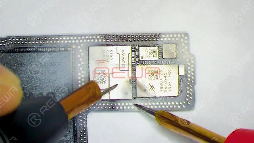
Then connect the black probe to the ground and connect the red probe to pin 113 on the logic board. We can see rosin on a capacitor has melted.
It indicates that the component is damaged. This circuit has multiple filter capacitors, so we can directly remove the damaged capacitor.
Remove the capacitor with Hot Air Gun at 350℃ and airflow 3.
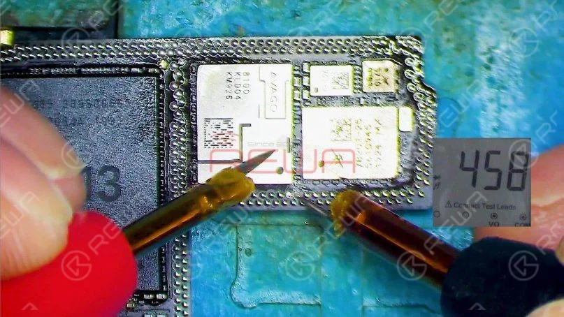
Measure the logic board again after it has cooled. The diode value returns to a normal value of 458.
Step 3: Motherboard restoration
Next, we need to restore the motherboard.
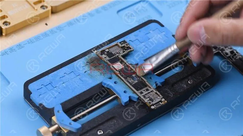
Firstly, we need to remove tin on the bonding pad of the motherboard.
Smear rosin with Soldering Iron at 365℃ and solder-wick to remove tin on the bonding pad.
Remove tin on the signal board with the same method.
After that, clean the logic board and signal board with PCB Cleaner.
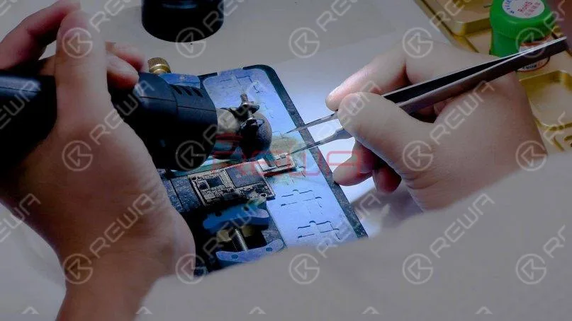
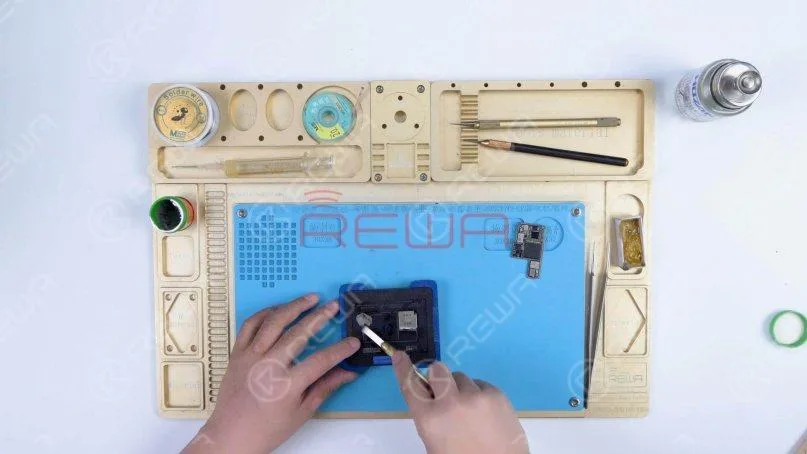
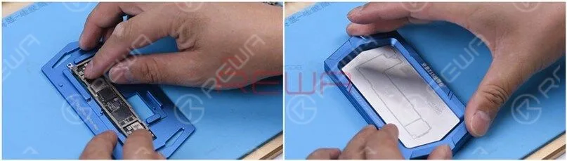
Next, attach the signal board to the Reballing Platform and put the Reballing Stencil in position.
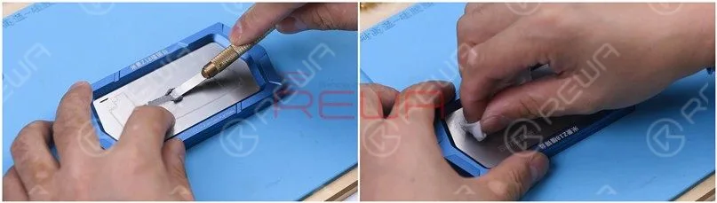
Apply a layer of medium-temperature Solder Paste evenly.
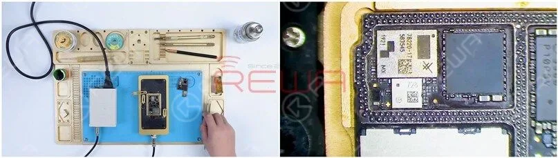
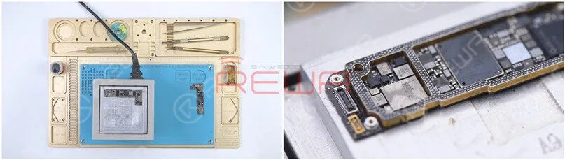
After reballing, put the signal board on the 185℃ Heating Platform to heat.
When the solder balls are formed, turn the power off and cool the signal board.
Apply some Paste Flux to the bonding pad of the signal board and align the logic board with the signal board.
Keep heating the motherboard on the 185℃ Heating Platform.
Push the logic board gently with tweezers and the logic board can return to the previous position.
It shows that the motherboard has completed soldering.
Turn the power off and cool the motherboard for 5 minutes.
Then remove the motherboard and install it on the phone.
The phone turns on normally and the 4G signal can be received.
A phone call can also be made. The fault is cleared.
Summary
The iPhone 11 Pro Max has been repaired once and still has no service after the baseband CPU and EPROM has been welded to a good signal board.
It can be preliminarily judged that there are two possible faults. One is the damage of baseband CPU and baseband EPROM. The other is the damage of circuits related to the signal on the logic board.
Through measuring the signal pads on the logic board and rosin detecting, a capacitor was found damaged.
After removing the capacitor, the no service fault was cleared.
We can rule out the possibility of baseband CPU and EPROM fault since the no service fault was eliminated after repairing the logic board.
If you want to study more, please feel free to visit our academy for repair courses.
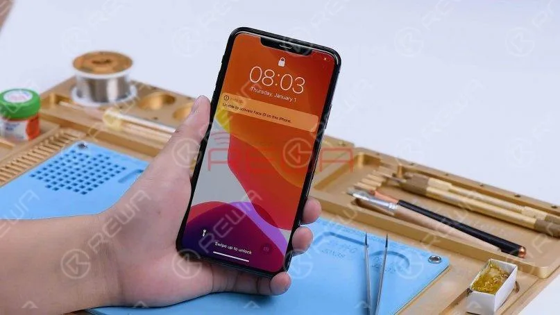
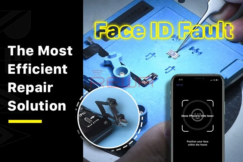
Dot projector parts are extremely fragile. A fall or water damage may harm dot projector parts, inducing Face ID not working.
This article explores a breakthrough method developed by REWA LAB for repairing Face ID, making it accessible and effective.
The Problem
The heart of Face ID lies in the dot projector integrated circuit (IC), a critical and encrypted component. Replacing this IC necessitates a complex process involving data encryption bonding, which repair technicians typically find daunting.
The Solution
Fortunately, REWA LAB has devised a streamlined and efficient approach to resolve Face ID issues.
The step-by-step guide presented here will help you understand and perform the repair procedure.
Step 1: Initial Diagnosis
Begin by navigating to your device’s Settings, then select “Face ID & Passcode” and “Set Up Face ID.”
During the setup process, you may encounter the message “Move iPhone a little lower/higher.” This indicates a malfunction in the dot projector.
Step 2: Disassembly
To access the dot projector, remove the device’s display.
If you observe a red mark, it suggests that the phone has experienced water damage.
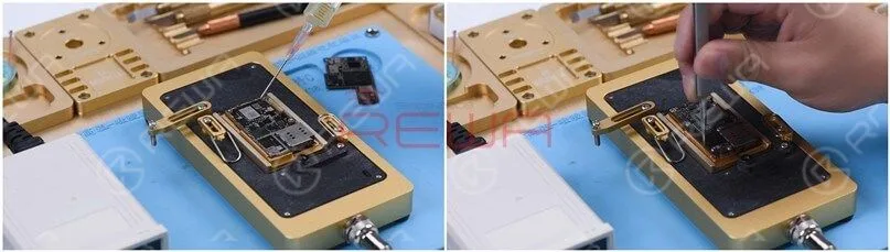
Connect the dot projector flex cable to the I2C Repair Programmer and perform a diagnostic test, confirming a malfunction.
Step 3: Data Transfer and Crystal Fix
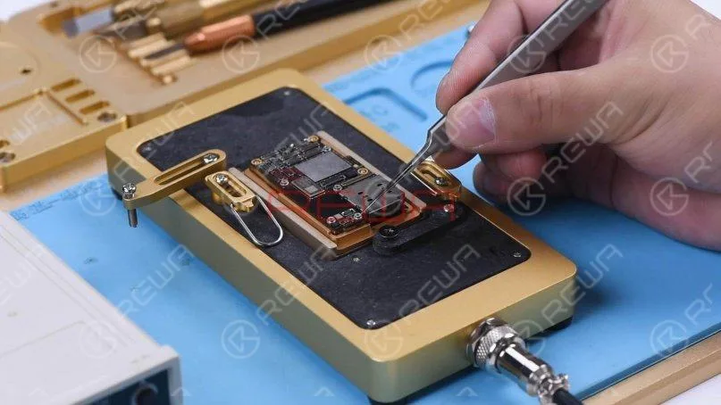
Use the programmer to read data from the malfunctioning flex cable.
Replace the flex cable with a new one and transfer the previously read data.
Apply a small amount of UV adhesive to secure the crystal of the dot projector flex cable using a UV lamp.
Step 4: Removing the Dot Projector
Remove the foam covering the back of the dot projector.
For precise alignment during reassembly, mark the module with a Sculpture Knife.
Lift the metal plate to access the dot projector flex cable beneath.
Step 5: Precision Work
Utilize a Holding Fixture for precise handling of the Face ID module.
Grind the welding position of the metal plate to access the dot projector.
Carefully detach the dot projector module using a Hot Air Gun.
Remove the MOSFET by heating at 320°C.
Step 6: Soldering and Reassembly
Apply Solder Paste to the bonding pad with a Soldering Iron and jump wire between pins 2 and 3 of the MOSFET using 0.02mm copper wire.
Clean the dot projector module with rosin and solder-wick, followed by PCB Cleaner.
Reball the new flex cable, apply Paste Flux, and solder it to the dot projector module.
Step 7: Testing and Final Assembly
Connect the soldered flex cable to the I2C programmer and run a test.
If the test passes, attach the flex cable to the Holding Fixture and align it with the dot projector module.
Apply 460 Adhesive to secure the components.
Install the flex cable in the phone.
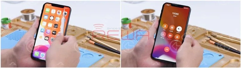
Power up the device and configure Face ID settings.
Conclusion
By following these meticulous steps, you can successfully restore your device’s Face ID functionality. The fault will be cleared, and your phone will regain its secure and convenient authentication feature.
Please feel free to visit our online shop for repair parts and tools.
Watch the video below to get a more detailed iPhone 11 Pro Max Face ID repair.
Many iPhone 8 and iPhone 8 Plus users have reported experiencing low call volume, making it difficult to hear during phone calls. Since making and receiving calls is one of the most basic functions of a mobile phone, solving this issue is crucial. Below, we’ll cover several troubleshooting steps to help resolve low call volume on iPhone 8/8 Plus.
Identify the Cause of Low Call Volume
Before diving into solutions, it’s important to identify the root cause of the low call volume. Here are a few checks you can perform:
Step 1: Check Volume Levels
Make sure the call volume on your device isn’t set to a low level by using the volume buttons.
Ensure it’s not the caller’s microphone or volume settings causing the issue.
Step 2: Check for Low Volume During Calls
If the volume is still low during calls, consider the following:
The issue could be with the caller’s microphone.
Verify that your phone’s receiver isn’t obstructed by a case or screen protector.
Check your network signal strength to ensure it’s not a connection issue.
Inspect your phone’s settings for any misconfigurations affecting the call volume.
Troubleshooting Methods to Resolve Low Call Volume
Once you’ve identified the potential cause, try the following troubleshooting methods to fix the problem:
Method 1: Increase Volume
Press the volume up button on the side of your iPhone during a call to increase the call volume.
Method 2: Enable Hearing Aid Compatibility
Navigate to Settings > General > Accessibility.
Under Hearing Devices, enable Hearing Aid Compatibility to enhance the audio.
Method 3: Adjust Phone Noise Cancellation
Go to Settings > General > Accessibility.
Under Audio/Visual, toggle off Phone Noise Cancellation. This can sometimes improve the call volume, especially in noisy environments.
Method 4: Use Original Headphones
Insert Apple’s original headphones during a call, and then unplug them. This method has resolved low call volume issues for some users by resetting the audio pathways.
Method 5: Restart Your Phone
If none of the above steps work, try restarting your iPhone. Sometimes, a simple restart can fix minor glitches affecting the call volume.
Method 6: Update or Delete Apps
If you experience low call volume while using certain apps, it may be due to an app issue. Check for updates or uninstall the app if it continues to cause problems.
What If None of the Methods Work?
If the low call volume problem persists after trying all the methods above, there may be a deeper hardware issue or software glitch. In this case, it’s recommended to:
Seek further technical assistance.
Contact Apple Support for more advanced troubleshooting or repairs.
Conclusion
While a low call volume on your iPhone 8/8 Plus can be frustrating, the issue is often resolved through a few simple troubleshooting steps. From adjusting your phone’s volume settings to enabling Hearing Aid Compatibility, these methods can help you improve your call experience. If these solutions don’t work, seeking professional help from Apple Support may be necessary.
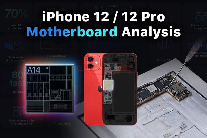
Compared with the iPhone 11 series, the motherboard separation of the iPhone 12 has become more difficult with different components structure.
Today, REWA LAB will separate the iPhone 12 motherboard, demonstrating the separation and recombination operation process.
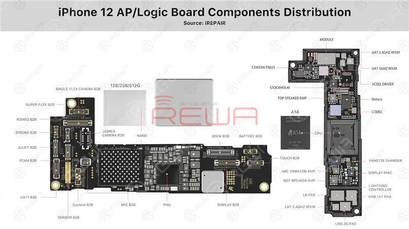
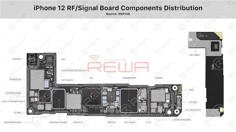
This article will give you a comprehensive analysis of the structure and repair difficulties.
Part 1 Motherboard Separation
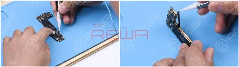
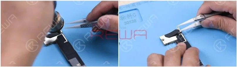
Remove the foam on the motherboard with tweezers and then take the sticker around the motherboard off.
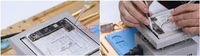
Heat the motherboard with Hot Air Gun at 180℃ and remove the plastic part.
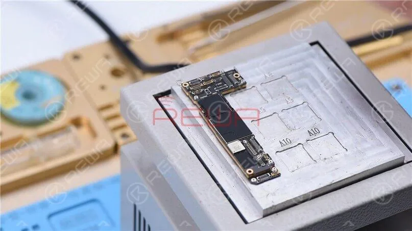
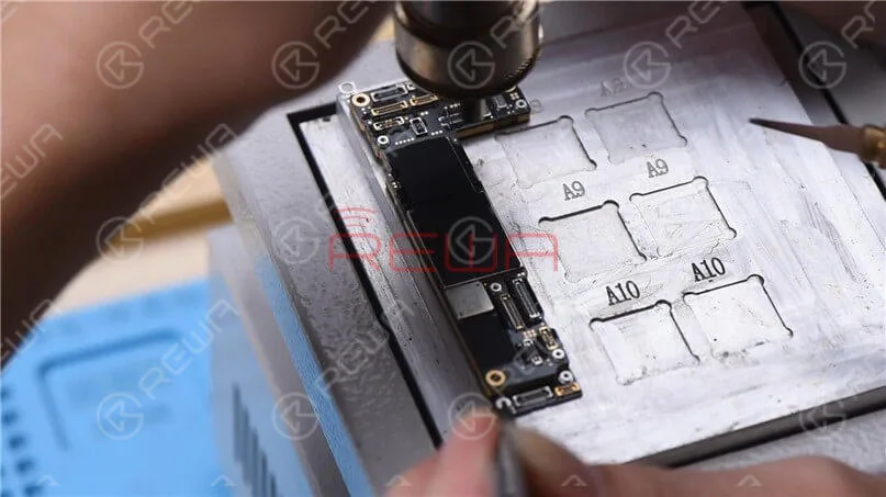
Put the motherboard on the Heating Platform.
Since the Heating Platform for iPhone 12 has not come out yet, we adopt the universal Heating Platform.
Please notice that it requires two people to separate the motherboard here.
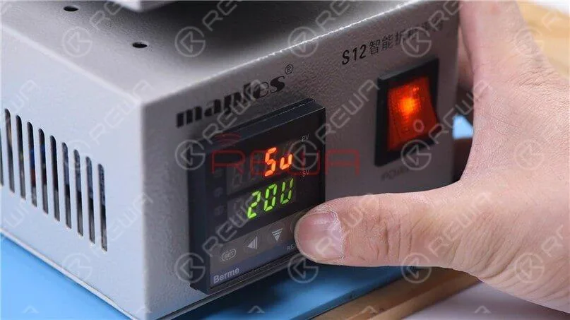
Besides, since the middle layer of the iPhone 12 motherboard uses middle-temperature tin soldering which is different from the low-temperature tin adopted in iPhone 11 Pro, the temperature of the heating platform needs to be adjusted to 200℃.
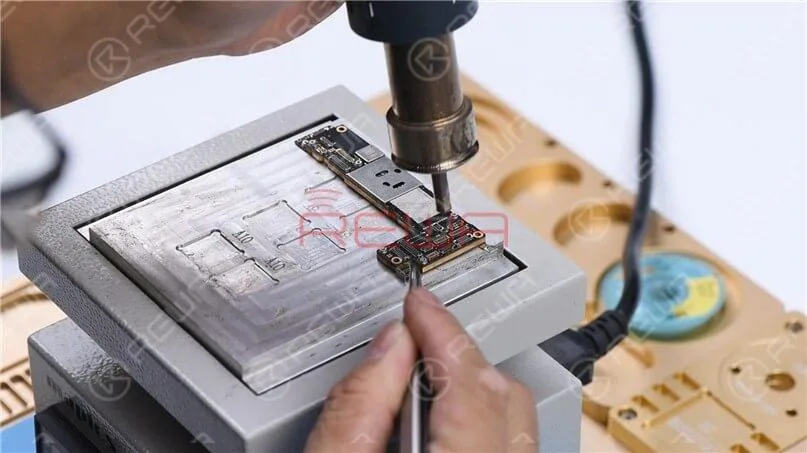
When the temperature reaches 200℃, heat the edge of the motherboard with rotational air (QUICK 861D Hot Air Gun at 320℃).
Please be noted that excessive heating may lead to pseudo soldering or falling off of parts.
Two rounds of vertical heating are advisable.
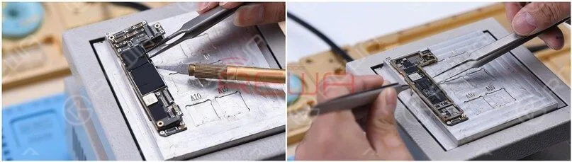
Remove the upper layer and lower layer.
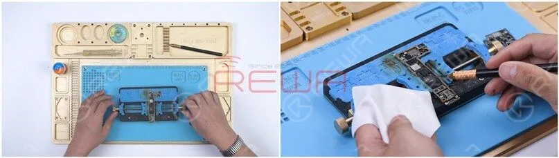
Attach the lower layer to the PCB Holder and remove the thermal grease.
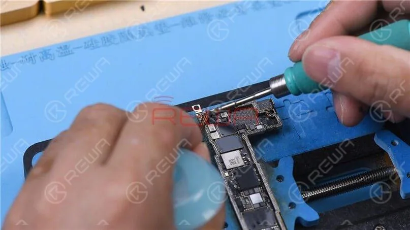
To clean the tin on the bonding pad, smear rosin with Soldering Iron at 400℃ and solder-wick.
The middle layer of the motherboard uses middle-temperature tin soldering, which makes it harder to clean than the low-temperature tin.
Clean the bonding pad with PCB Cleaner and then handle the upper layer in the same way.
Part 2 Motherboard Recombination
Then we recombine the upper layer and lower layer.
Attach the lower layer to the Reballing Platform and put the Reballing Stencil in position.
Apply some middle-temperature Solder Paste and wipe residual Solder Paste with lint-free wipe.
Heat the lower layer with the Heating Platform at 200℃.
After the solder ball is formed, turn the power off and cool the motherboard for 5 minutes.
Apply some Paste Flux to the bonding pad evenly.
Align the upper layer with the lower layer.
After the alignment, keep heating the motherboard at 200℃.
To add extra heat, heat along the edge of the motherboard with Hot Air Gun at 320℃.
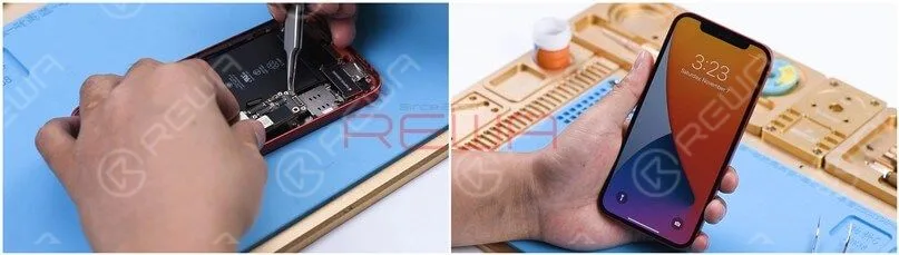
After cooling the motherboard for 5 minutes, put it back on the phone.
Boot up and test. The phone turns on normally.
Part 3 Motherboard Appearance Comparison
The iPhone 12 in our hand is not a U.S. version.
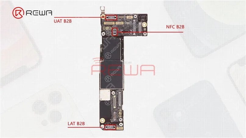
As its 5G network frequency band adopts the Sub-6G, there are primarily three antenna connection seats (upper antenna, NFC antenna, and lower antenna).
By contrast, the U.S. version iPhone will feature an extra mmWave antenna while the motherboard will have an additional mmWave antenna connector seat.
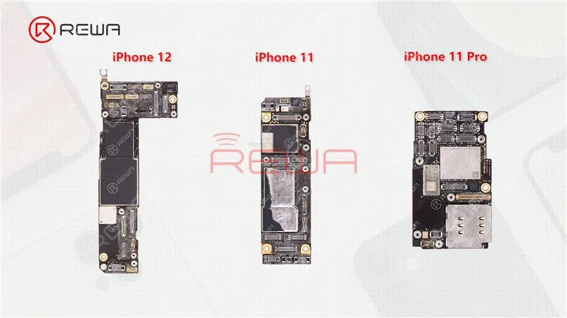
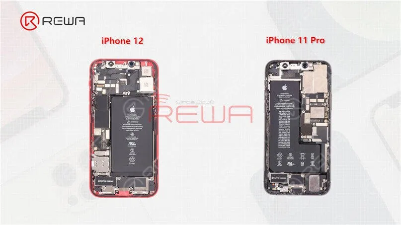
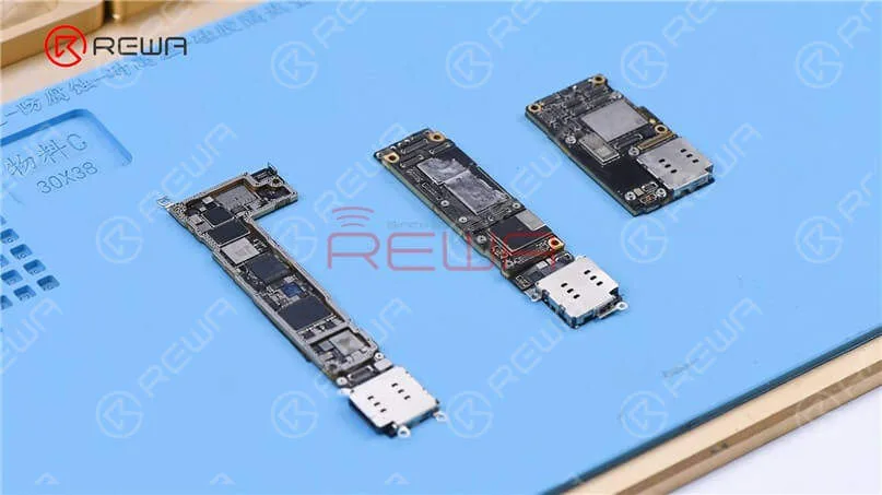
In addition to differences in the outer look, the layout of the three motherboards is also different.
The motherboard of the iPhone 12 is placed on the left while the motherboard of the iPhone 11 and iPhone 11 Pro is placed on the right.
As the new iPhone 12 lineup requires the baseband and chip of 5G to be added to the motherboard,
Apple may need to redesign the motherboard and its layout.
Next, let’s take a look at the separation of the iPhone 12 sandwich board.
Part 4 Analysis of the motherboard
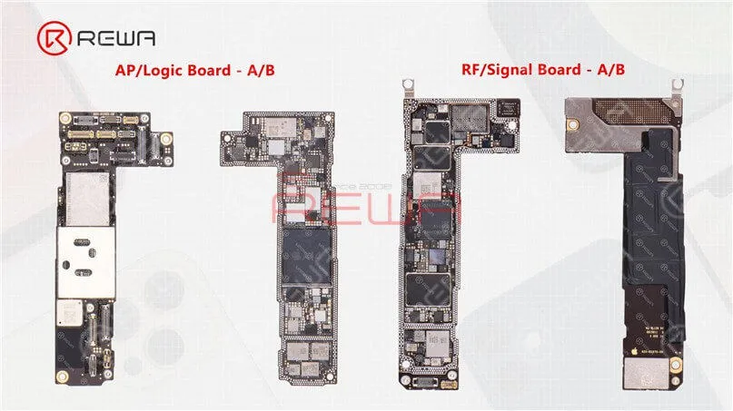
(1) The upper layer and lower layer of the iPhone 12
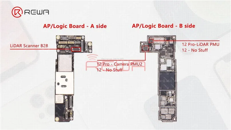
As we mentioned in our previous video, the motherboard of the iPhone 12 and iPhone 12 Pro is almost identical in appearance with the double-stacked soldering.
The sole difference is that the connecting part of the LiDAR Scanner on the iPhone 12 motherboard has no stuff.
Beyond that, we can see two empty parts on the upper layer after separation.
The two parts are additionally reserved for the Camera PMU2 and LiDAR PMU on the iPhone 12 Pro motherboard.
(2) A14 Chip
The A14 chip nanometer process, which develops from the A13 chip, goes from 7nm to 5nm.
As the first 5-nanometer chip in the industry, A14 Bionic is faster than every other smartphone chip.
With A14 Bionic, the CPU, GPU, and machine learning abilities of the iPhone 12 lineup have been improved substantially.
(3) Power Management Chip
According to Bloomberg, Apple is said to face shortages in power chips for iPhone 12.
Power management is more important in the iPhone 12 than for its predecessors given additional camera features and 5G capabilities, increasing Apple’s need for these parts.
(4) Card Slot
The SIM card slot of the iPhone 12 series adopts a stand-alone design that is connected via flex cable.
In case of any fault related to the card slot during repair, you only need to replace the stand-alone card slot.
For comparison, the iPhone 11 card slot is also connected to the motherboard via flex cable, but it is embedded on the motherboard for iPhone 11 Pro series.
(5) Lightning Connector Flex Cable
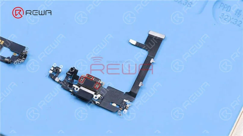
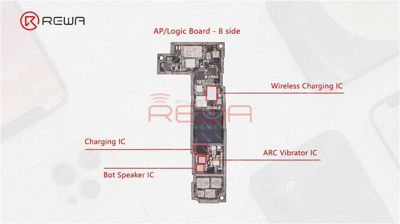
The lightning connector flex cable of the iPhone 11 Pro integrates Bot Speaker IC, ARC Vibrator IC, Charging IC, and Wireless Charging IC, which increases the possibility of functional failure in the case of water damage or heavy fall.
But these ICs are back on the iPhone 12 motherboard, which not only reduces the possibility of lightning connector functional failure but also makes it easier to repair in the case of water damage or heavy fall.
(6) Face ID Parts Comparison
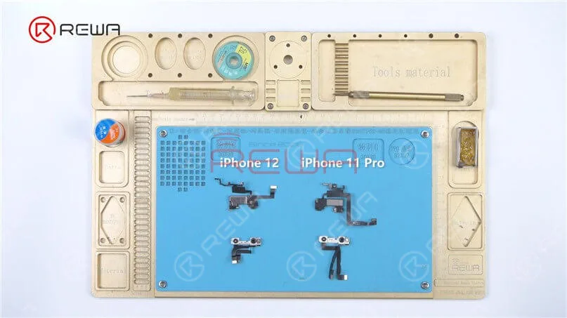
Take the Face ID parts of the iPhone 12 and iPhone 11 Pro to compare.
In appearance, the iPhone 12 Face ID front camera module looks much the same as the previous iPhone 11, with some changes to the metal frame and flex cable.
The layout of the infrared camera, front camera, and dot projector remains unchanged.
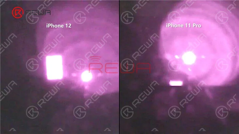
It can be seen from the microscope and camera lens that the flood illuminator module at the ear speaker flex cable is different.
The lighting area of the iPhone 12 flood illuminator is larger.
Some iPhone users may encounter such a problem, when the phone screen is turned off, we cannot receive the call.
Right now, there are few solutions to fix iPhone not responding in sleep mode when getting incoming calls.
The general repair process of a repair technician is to take out the motherboard, check PMU and baseband CPU, and then replace or re-solder the faulty component.
The whole repair process is complicated and difficult.
Now REWA LAB will show you a brand new ‘signal borrowing’ solution to fix this problem quickly and efficiently.
Problem
Here we have an iPhone X not responding in sleep mode when getting incoming calls. When we were trying to test the Sounds&Haptics function, we found all going well.
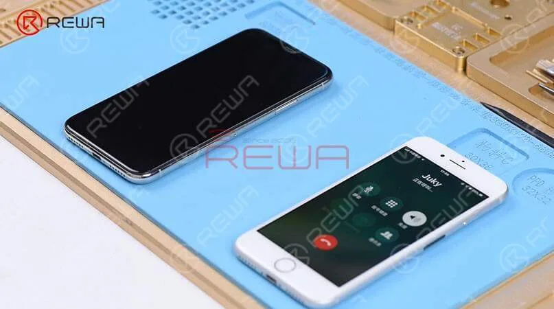
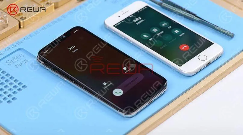
With the screen on, we placed a call to the phone using a known-good phone. And the decline and answer buttons appear on the screen.
However, if we turned the screen off, the phone is not responding at all. Then we pressed the power button to turn the screen on and we can see the incoming calls showing on display.
Diagnosis
Judging by this, we can infer that relevant circuits of the baseband wake signal might have malfunctioned. So we took apart the phone, disconnected the battery, removed the display assembly, and took out the motherboard.
The following step is to attach the motherboard to the PCB Holder and then heat with Hot Air Gun at 200℃, airflow 3 to tear off the heat dissipation sticker on the backside of the motherboard.
Confirm the Signal Fault Location
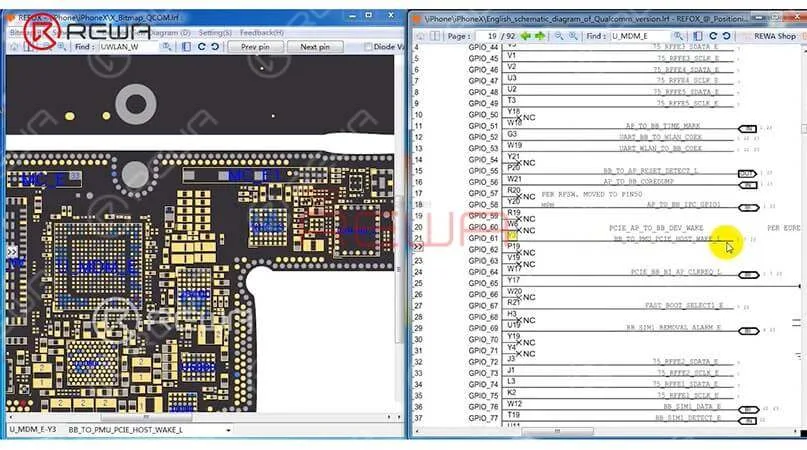
We can open the bitmap software in Refox and locate BB_TO_PMU_PCIE_HOST_WAKE_L first.
Since relevant circuits of the wake signal might have malfunctioned, so we can try to borrow the wake signal from WiFi relevant circuits.
Borrow Signal by Jumping a wire
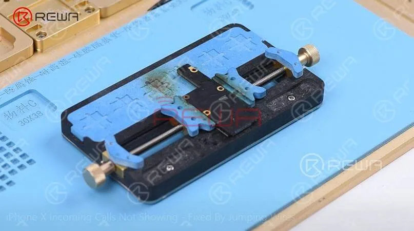
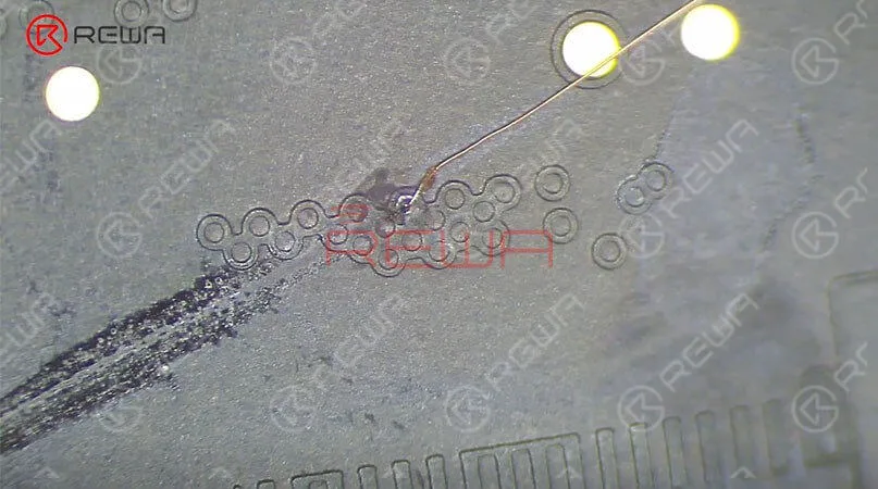
Then we need to locate WLAN_TO_PMU_HOST_WAKE. And the following step is to connect PP101_E-1 (the test point of the baseband wake signal) with PP7611_W-1 (the test point of the WiFi wake signal) by jumping a wire.
Before that, we need to scrape off the insulating coating on the two test points first, then apply some solder paste to the two bonding pads and heat with Soldering Iron at 365℃.
The next step is to tin the two bonding pads with solder paste and also to connect PP101_E-1 to PP7611_W-1 with 0.02mm Enameled Copper Wire.
Finally we need to coat the wire with the UV Curable Solder Mask.
Assemble the Phone and Test
Now we can assemble the phone and test. We got the motherboard installed and displayed assembly connected, then connected the battery.
Then pressed the power button to turn on the phone inserted the SIM card. After that, with the screen off, we tested again. And we found all going well.
PS: The repair case of this blog is applicable to the QCOM version, which might be a reference for the Intel version as a repair method.
iPhone gets stuck on the Apple logo, which usually means that there is a problem with the operating system or hardware of the phone.
Today, we will show you a rare case of iPhone X stuck on apple logo, and teach you how to diagnose and fix the problem step by step.
Cosmetic Inspection
As we always do, we should run a cosmetic inspection of the motherboard first.
Check out the condition of the motherboard, whether it is deformed or water damaged.
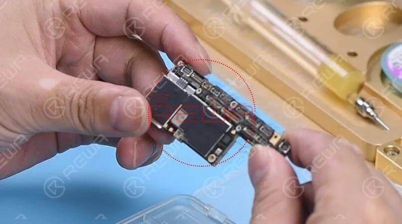
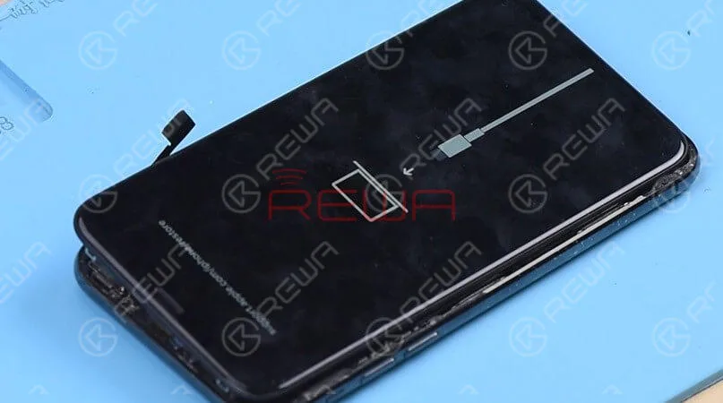
Then get the motherboard installed, the phone enters into recovery mode automatically.
Judging by this, the motherboard comes with restore failure. Therefore, the phone cannot enter into the system normally.
Diagnosis
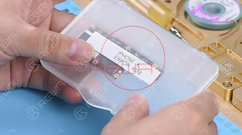
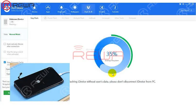
Let’s restore the phone with 3U Tools and check whether it comes with error 4013.
The phone can be normally activated after restore.
Next, check baseband info in the settings. If it shows normal, we can confirm now that the motherboard is normal. The fault is probably related to other parts.
Get the earpiece speaker and sensor flex cable and front camera flex cable installed.
Turn on the phone, the phone is stuck on the Apple logo and keeps restarting.
Judging by this, the fault is related to the earpiece speaker and sensor flex cable or the front camera flex cable.
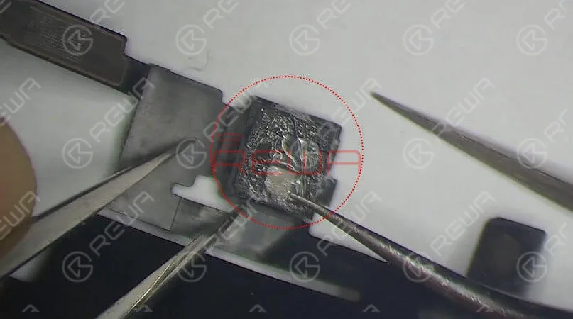
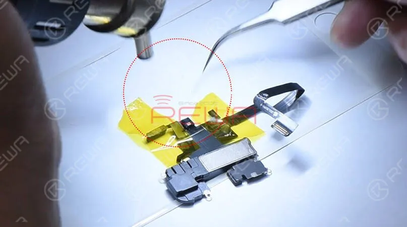
Check the earpiece speaker and sensor flex cable carefully, we find that the Flood illuminator module is moldy.
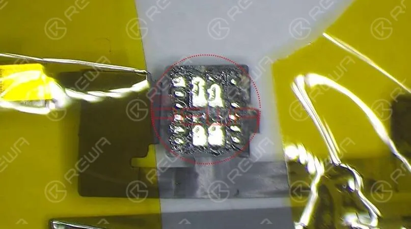
Remove the Flood illuminator module, we can see that its bonding pad is severely corroded.
That’s what’s causing the problem.
Maintenance
The next section will explain the detailed repair steps:
Apply some paste flux to the bonding pad.
Clean the bonding pad with Soldering Iron.
Apply solder paste to the severely corroded pad.
Clean with PCB Cleaner afterward.
Apply some paste flux to the bonding pad.
Get the Flood illuminator module in the right position.
Solder it with Hot Air Gun.
Test
Get the earpiece speaker and sensor flex cable installed, then assemble the phone.
The phone turns on normally. Since the two flex cables were not connected during the previous restore, we need to restore again with the two connected.
Restore the phone with the help of 3U Tools.
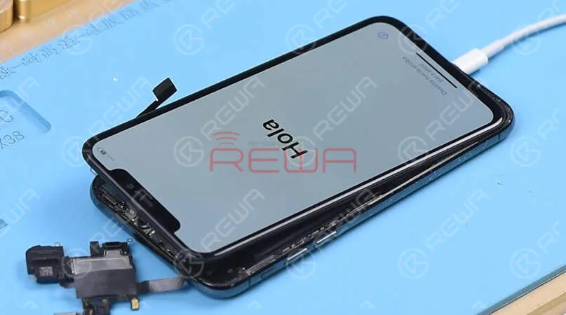
Once completed, the phone enters the system normally, and Face ID works normally.
The repair process requires not only professional theoretical knowledge but also proficient handwork skills.
Start your learning journey with REWA ACADEMY now!
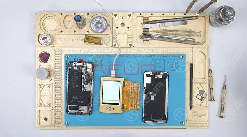
Attach a known good lower layer to the test fixture and then attach the upper layer.
Get the display assembly connected.
Running test, we can found that the phone turns on normally and the touch function is also normal.
Judging by this, the touch issue is caused by the lower layer.
Board Swap
Since the lower layer is badly deformed, we need to transplant baseband CPU, baseband EEPROM and the NFC chip on the original lower layer to a new lower layer.
For more details, please check out the video below:
After board swap, we should running test again by using Test Fixture.
Connect the battery connector with the DC Power Supply.
Then get the motherboard powered on with tweezers.
Here we can find IMEI serial number and modem firmware which indicates that the lower layer swap has been completed successfully.
Motherboard Recombination
Next thing we do is to solder the two layers together.
Here are the following steps:
Attach the new lower layer to the specialized reballing mold.
Cover the new lower layer with the matched reballing stencil.
Smear some low-temp Solder Paste on the stencil.
remove the reballing stencil carefully.
Continue to place the new lower layer onto the heating platform.
Waiting for the solder paste melting, solder balls start to shape up.
Waiting for the lower layer to cool for 10 minutes.
Apply BGA Paste Flux to the third space PCB, get the upper layer in position.
Heat for 1 minute on the heating platform at 160 degrees.
With the upper layer sinking and Paste Flux flowing, the two layers have been soldered together successfully.
Wait for the double-stacked motherboard to cool for 5 minutes.
True Tone Restoration
After we finish repairing the motherboard, it’s time to transplant parts.
REWA has years of experience on providing wholesale services upon an extensive range of electronic related products covering mobile phone spare parts and replacement battery.
We adhere to the principle of ” Quality Above All ” through the whole producing and testing processes. Here are some of our selected products:
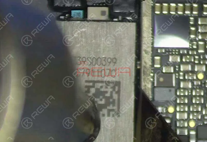
Heat with the QUICK 990AD Hot Air Gun to remove black adhesive around the NAND flash chip.
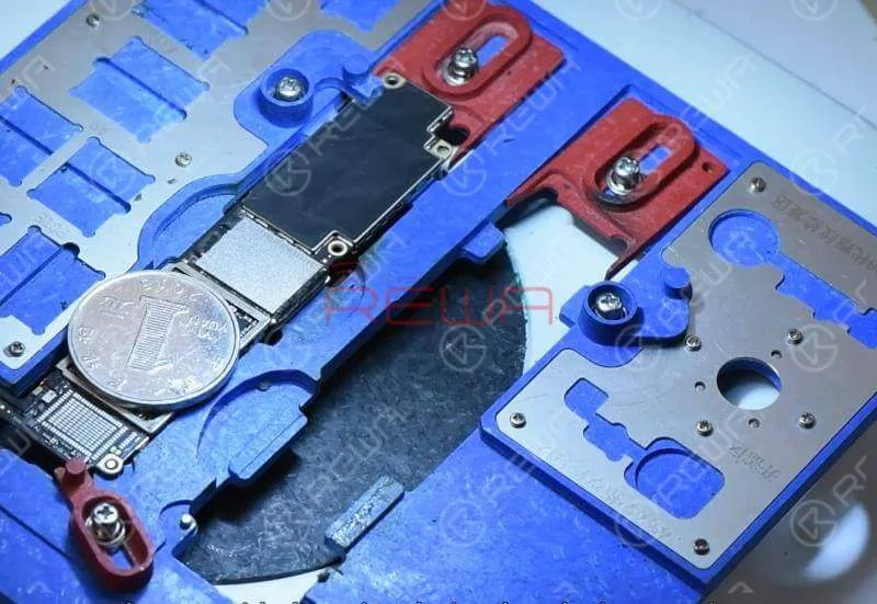
Since there are multiple components around the NAND flash chip, to protect these components from high-temperature damage, we need to provide heat insulation by placing a coin.
Once the NAND flash chip has been removed, continue to apply some Paste Flux to the bonding pad and then some middle-temperature solder paste.
Heat with the Soldering Iron to neutralize the melting temperature on the bonding pad.
Continue to apply Paste Flux to the detached NAND flash chip and clean the NAND flash chip with the Soldering Iron.
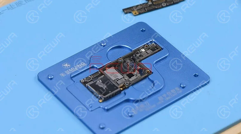
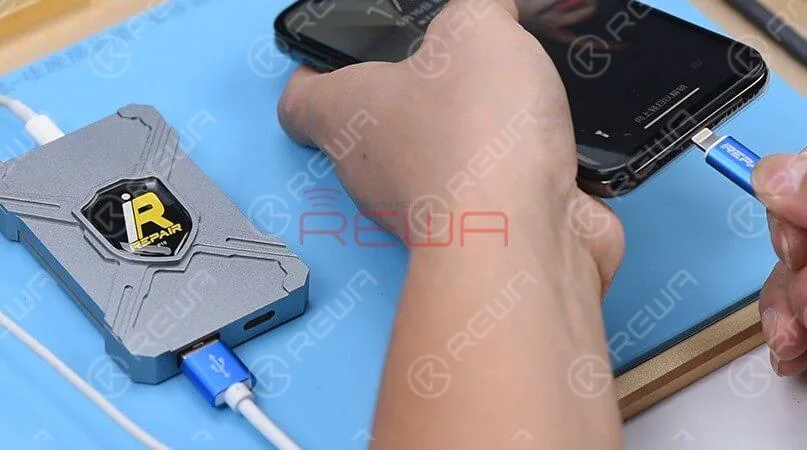
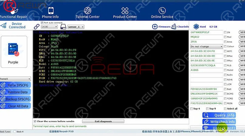
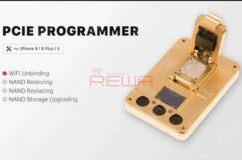
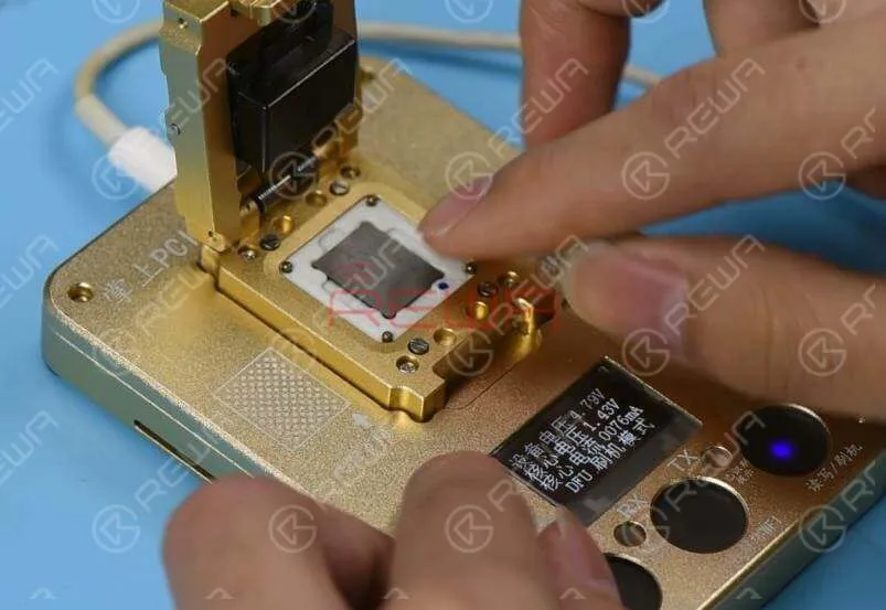
Place the NAND flash chip into the PCIE Programmer and run the software to complete WiFi unbinding. Once done, take out the NAND flash chip.
NAND Reballing
Next, we need to reball the NAND flash chip.
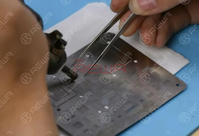
Get the BGA Reballing Stencil well aligned with the chip.
Smear Soldering Paste evenly on the BGA reballing stencil and then heat evenly with the QUICK 990AD Hot Air Gun so that all solder balls can solidify completely.
Once done, separate the chip from the BGA reballing stencil and clean the NAND flash chip with PCB Cleaner afterwards.
Chip Soldering
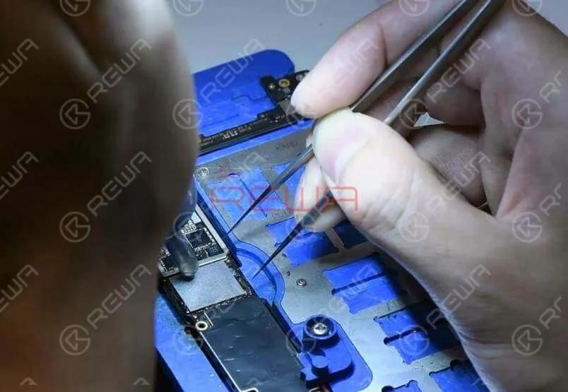
Now we can solder the NAND flash chip and a new WiFi module onto the board.
Apply some Paste Flux to the bonding pad.
Get the NAND flash chip in position.
Make sure you put it in the right direction.
Solder with the QUICK 990AD Hot Air Gun.
Continue to apply Paste Flux to the bonding pad of the WiFi module and get a new WiFi module in position. Solder with the QUICK 990AD Hot Air Gun afterwards.
Reassemble And Test
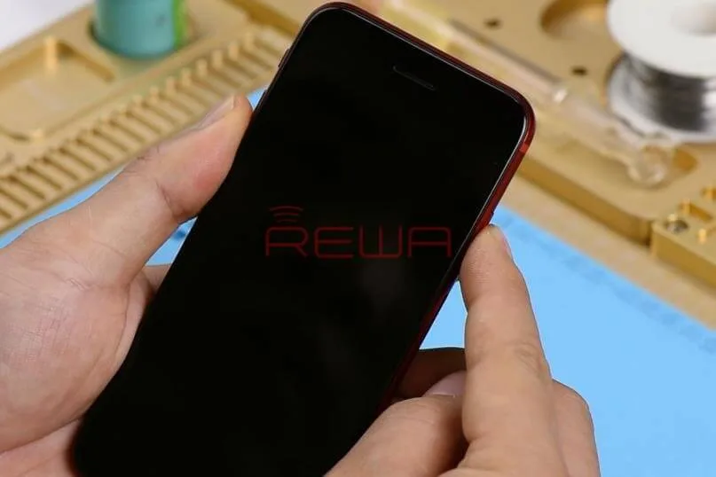
Now we can assemble the phone and test. Get the logic board and display assembly installed. Connect the battery and press the power button.
The phone turns on normally.
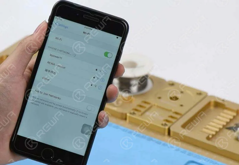
Go to Settings>WiFi. The WiFi switch is back to normal. Networks in range can be picked normally. Fault cleared.
The CPU of mobile phones functions much like the brain of our body, making it a critical component.
When it comes to mobile phone repair, addressing CPU issues can be quite complex.
In this article, we will explore how to troubleshoot and repair a common problem with the iPhone 7 not turning on, attributed to pseudo soldering of the CPU.
Problem
No Response When Turning On the Phone
Press the power button, but there’s no response.
Power Supply Test
Disassemble the phone.
Connect the phone to the DC Power Supply.
Press the power button.
The current pointer remains static at 50mA-60mA.
Connect the phone to a computer; the device cannot be recognized, suggesting USB IC or logic board power supply issues.
Diagnosis
To diagnose and potentially resolve the issue:
Testing Power Supply
Remove the logic board.
Connect the battery connector to the DC Power Supply.
Test power button functionality.
Measure the 16 rails of the logic board power supply, ensuring the values are within normal ranges.
Replacing USB IC
If power supply measurements are normal, replace the USB IC.
Attach the logic board to the PCB holder.
Carefully remove part of the shield plate.
Detach the USB IC using a Hot Air Gun.
Clean the bonding pad.
Solder a new USB IC and test; if the problem persists, proceed to troubleshooting the CPU.
Troubleshooting
Upon identifying CPU-related issues:
Re-soldering the CPU
Remove the shield plate with a Hot Air Gun.
Apply high-temperature tape to protect nearby components.
Carefully detach the CPU from the board using a Hot Air Gun.
Clean the bonding pad and remove the solder from the CPU.
Reballing the CPU
Position the BGA Reballing Stencil.
Apply Solder Paste evenly on the stencil.
Heat the solder balls evenly with a Hot Air Gun.
Allow the CPU to cool for 2 minutes.
Apply BGA Paste Flux to the bonding pad.
Position the re-balled CPU and solder it with a Hot Air Gun.
Clean with PCB Cleaner.
Reassemble and Test
Now that the CPU-related issue has been addressed:
Reassembly
Install the logic board and the display assembly.
Connect the battery and press the power button.
Testing
The phone should turn on normally.
Run a function test to ensure that all components are functioning correctly.
Conclusion
By following these steps, you can successfully troubleshoot and repair CPU-related issues in mobile phones. In this specific case, the iPhone 7 not turning on due to pseudo soldering of the CPU, our comprehensive process has resolved the problem, allowing the device to function as expected.








 English
 Español
 Français
 Deutsch
 Italiano