Tag: phone repair

  • How To Fix iPhone X Incoming Calls Not Showing

    How To Fix iPhone X Incoming Calls Not Showing

    Some iPhone users may encounter such a problem, when the phone screen is turned off, we cannot receive the call.

    Right now, there are few solutions to fix iPhone not responding in sleep mode when getting incoming calls.

    The general repair process of a repair technician is to take out the motherboard, check PMU and baseband CPU, and then replace or re-solder the faulty component.

    The whole repair process is complicated and difficult.

    Now REWA LAB will show you a brand new ‘signal borrowing’ solution to fix this problem quickly and efficiently.

    Problem
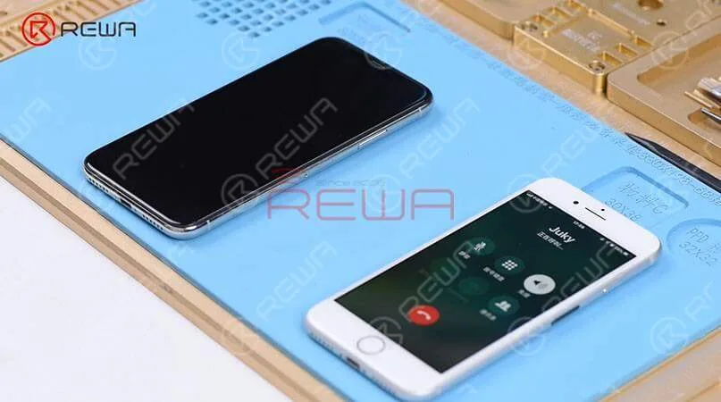
    Here we have an iPhone X not responding in sleep mode when getting incoming calls. When we were trying to test the Sounds&Haptics function, we found all going well. With the screen on, we placed a call to the phone using a known-good phone. And the decline and answer buttons appear on the screen. However, if we turned the screen off, the phone is not responding at all. Then we pressed the power button to turn the screen on and we can see the incoming calls showing on display.

    Here we have an iPhone X not responding in sleep mode when getting incoming calls. When we were trying to test the Sounds&Haptics function, we found all going well.

    With the screen on, we placed a call to the phone using a known-good phone. And the decline and answer buttons appear on the screen.

    However, if we turned the screen off, the phone is not responding at all. Then we pressed the power button to turn the screen on and we can see the incoming calls showing on display.

    Diagnosis
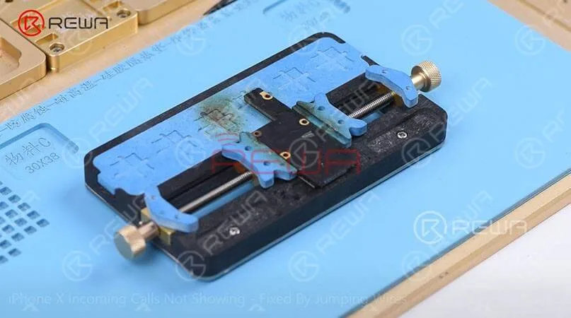
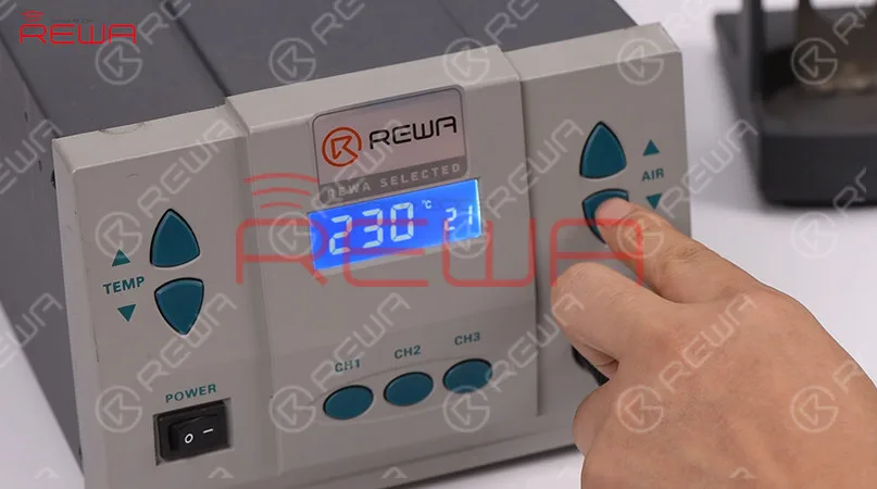
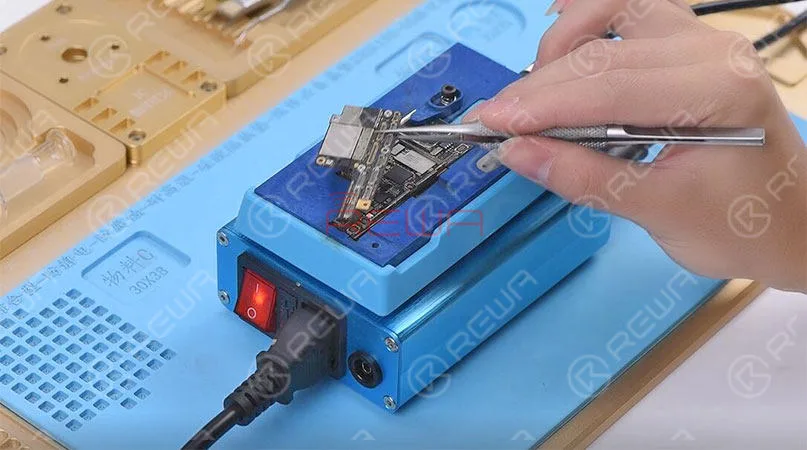
    The following step is to attach the motherboard to the PCB Holder and then heat with Hot Air Gun at 200℃, airflow 3 to tear off the heat dissipation sticker on the backside of the motherboard.

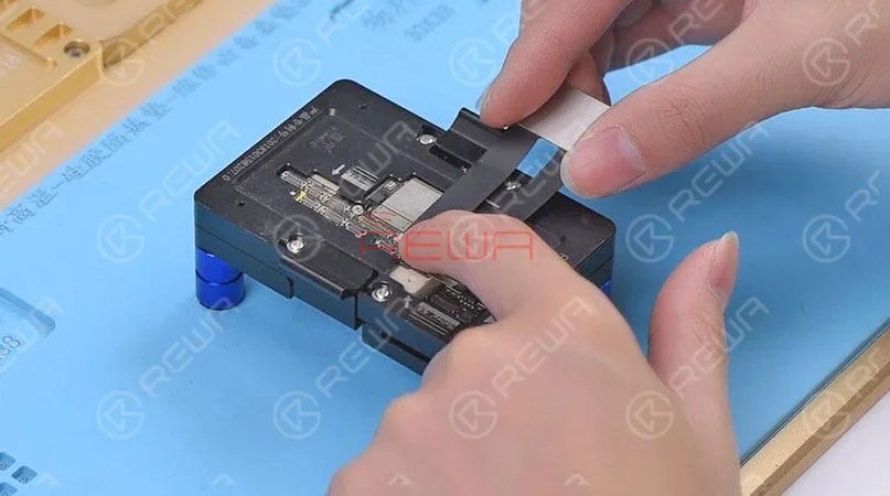
    Judging by this, we can infer that relevant circuits of the baseband wake signal might have malfunctioned. So we took apart the phone, disconnected the battery, removed the display assembly, and took out the motherboard.

    The following step is to attach the motherboard to the PCB Holder and then heat with Hot Air Gun at 200℃, airflow 3 to tear off the heat dissipation sticker on the backside of the motherboard.

    Confirm the Signal Fault Location
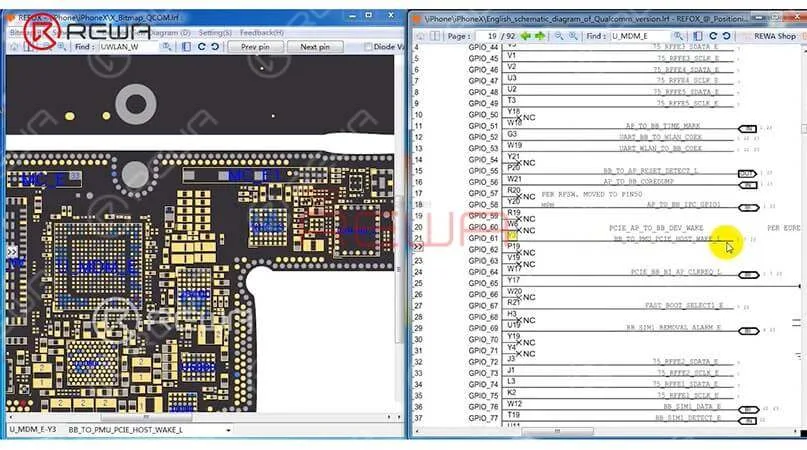
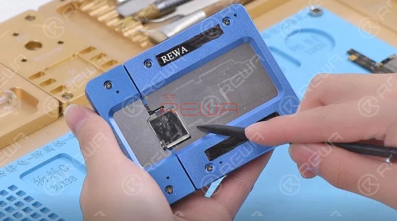
    We can open the bitmap software in Refox and locate BB_TO_PMU_PCIE_HOST_WAKE_L first. Since relevant circuits of the wake signal might have malfunctioned, so we can try to borrow the wake signal from WiFi relevant circuits.

    We can open the bitmap software in Refox and locate BB_TO_PMU_PCIE_HOST_WAKE_L first.

    Since relevant circuits of the wake signal might have malfunctioned, so we can try to borrow the wake signal from WiFi relevant circuits.

    Borrow Signal by Jumping a wire
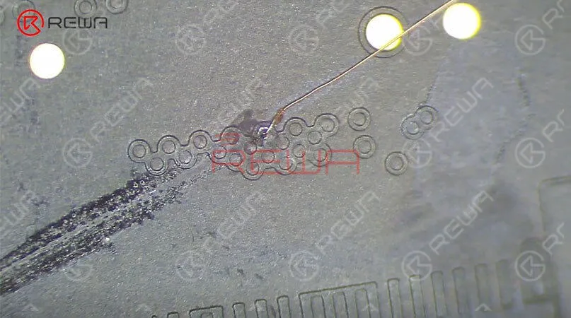
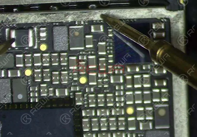
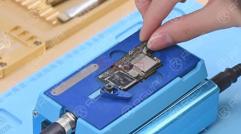
    Then we need to locate WLAN_TO_PMU_HOST_WAKE. And the following step is to connect PP101_E-1 (the test point of the baseband wake signal) with PP7611_W-1 (the test point of the WiFi wake signal) by jumping a wire

    Then we need to locate WLAN_TO_PMU_HOST_WAKE. And the following step is to connect PP101_E-1 (the test point of the baseband wake signal) with PP7611_W-1 (the test point of the WiFi wake signal) by jumping a wire.

    Before that, we need to scrape off the insulating coating on the two test points first, then apply some solder paste to the two bonding pads and heat with Soldering Iron at 365℃.

    The next step is to tin the two bonding pads with solder paste and also to connect PP101_E-1 to PP7611_W-1 with 0.02mm Enameled Copper Wire.

    Finally we need to coat the wire with the UV Curable Solder Mask.

    Assemble the Phone and Test
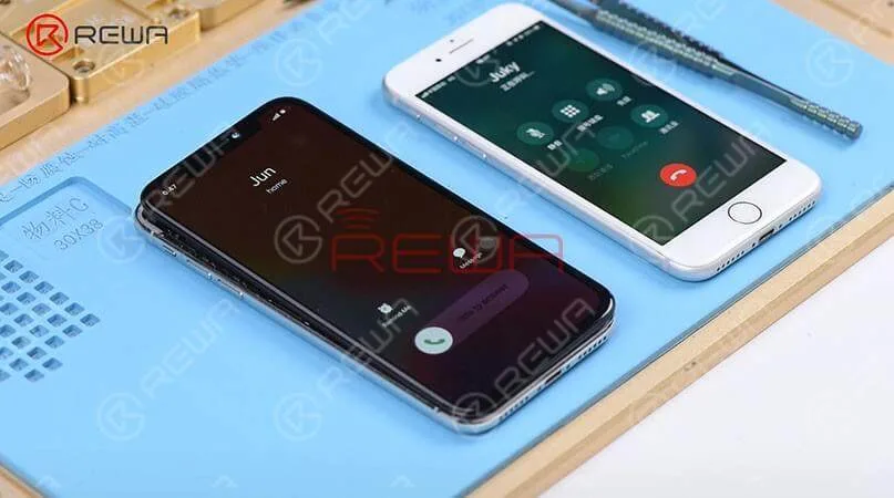
    Now we can assemble the phone and test. We got the motherboard installed and displayed assembly connected, then connected the battery. Then pressed the power button to turn on the phone inserted the SIM card.

    Now we can assemble the phone and test. We got the motherboard installed and displayed assembly connected, then connected the battery.

    Then pressed the power button to turn on the phone inserted the SIM card. After that, with the screen off, we tested again. And we found all going well.

    PS: The repair case of this blog is applicable to the QCOM version, which might be a reference for the Intel version as a repair method.

    Visit our online shop for more parts and tools.You can also visit REWA YouTube Channel to check our video.

  • A Rare Case Of iPhone X Stuck On Apple Logo(iTunes Error 4013)

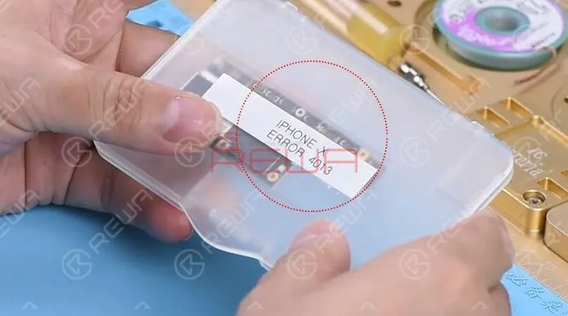
    A Rare Case Of iPhone X Stuck On Apple Logo(iTunes Error 4013)

    iPhone gets stuck on the Apple logo, which usually means that there is a problem with the operating system or hardware of the phone.

    Today, we will show you a rare case of iPhone X stuck on apple logo, and teach you how to diagnose and fix the problem step by step.

    A Rare Case Of iPhone X Stuck On Apple Logo(iTunes Error 4013)

    Cosmetic Inspection

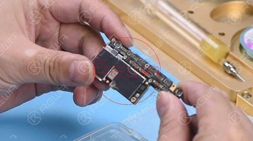
    we should run a cosmetic inspection of the motherboard first. Check out the condition of the motherboard, whether it is deformed or water damaged.
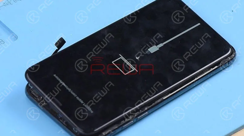
    Then get the motherboard installed, the phone enters into recovery mode automatically. Judging by this, the motherboard comes with restore failure. Therefore, the phone cannot enter into the system normally.

    As we always do, we should run a cosmetic inspection of the motherboard first.

    Check out the condition of the motherboard, whether it is deformed or water damaged.

    Then get the motherboard installed, the phone enters into recovery mode automatically.

    Judging by this, the motherboard comes with restore failure. Therefore, the phone cannot enter into the system normally.

    Diagnosis  

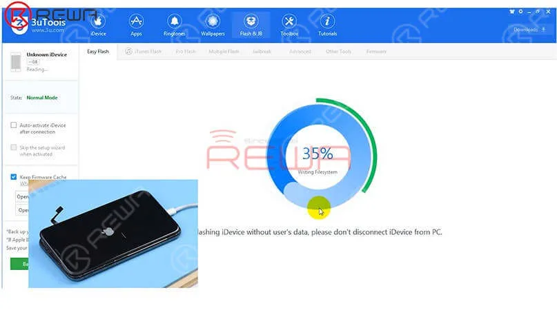
    Let’s restore the phone with 3U Tools and check whether it comes with error 4013.

    The phone can be normally activated after restore.

    Next, check baseband info in the settings. If it shows normal, we can confirm now that the motherboard is normal. The fault is probably related to other parts.

    estore the phone with 3U Tools and check whether it comes with error 4013.

    Get the earpiece speaker and sensor flex cable and front camera flex cable installed.

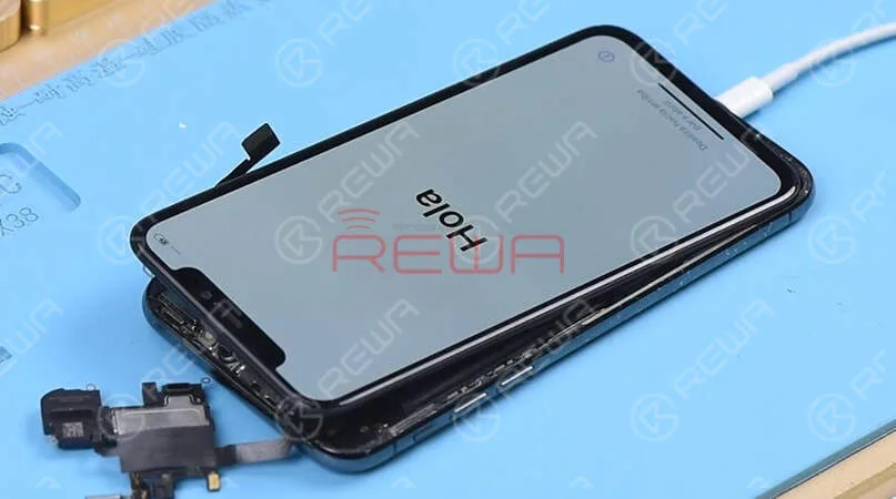
    Turn on the phone, the phone is stuck on the Apple logo and keeps restarting.

    Judging by this, the fault is related to the earpiece speaker and sensor flex cable or the front camera flex cable.

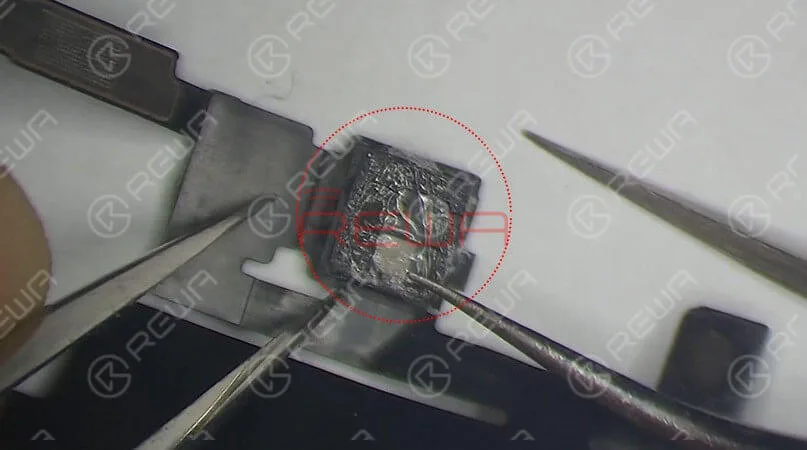
    Check the earpiece speaker and sensor flex cable carefully, we find that the Flood illuminator module is moldy. Remove the Flood illuminator module, we can see that its bonding pad is severely corroded. That's what's causing the problem.

    Check the earpiece speaker and sensor flex cable carefully, we find that the Flood illuminator module is moldy.

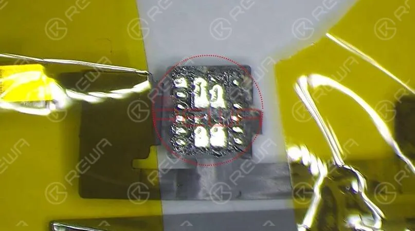
    Remove the Flood illuminator module, we can see that its bonding pad is severely corroded.

    That’s what’s causing the problem.

    Maintenance

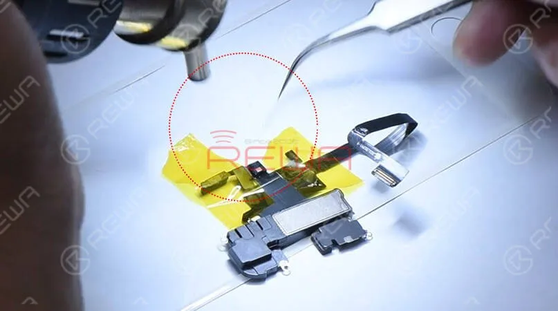
    The next section will explain the detailed repair steps:   Apply some paste flux to the bonding pad.   Clean the bonding pad with Soldering Iron.   Apply solder paste to the severely corroded pad.   Clean with PCB Cleaner afterward.   Apply some paste flux to the bonding pad.   Get the Flood illuminator module in the right position.   Solder it with Hot Air Gun.
    The next section will explain the detailed repair steps:   Apply some paste flux to the bonding pad.   Clean the bonding pad with Soldering Iron.   Apply solder paste to the severely corroded pad.   Clean with PCB Cleaner afterward.   Apply some paste flux to the bonding pad.   Get the Flood illuminator module in the right position.   Solder it with Hot Air Gun.

    The next section will explain the detailed repair steps:

    Apply some paste flux to the bonding pad.

    Clean the bonding pad with Soldering Iron.

    Apply solder paste to the severely corroded pad.

    Clean with PCB Cleaner afterward.

    Apply some paste flux to the bonding pad.

    Get the Flood illuminator module in the right position.

    Solder it with Hot Air Gun.

    Test

    Get the earpiece speaker and sensor flex cable installed, then assemble the phone. The phone turns on normally.

    Get the earpiece speaker and sensor flex cable installed, then assemble the phone.

    The phone turns on normally. Since the two flex cables were not connected during the previous restore, we need to restore again with the two connected.

    Restore the phone with the help of 3U Tools.

    Once completed, the phone enters the system normally, and Face ID works normally.

    The repair process requires not only professional theoretical knowledge but also proficient handwork skills.

    Start your learning journey with REWA ACADEMY now!

    Start your learning journey with REWA ACADEMY now!

    Preview this course:iPhone Logic Board Repair Handwork Course

    For more details on the operation, watch the video below:

  • iPhone X Restoration: Step-by-Step Guide for Professionals

    iPhone X Restoration: Step-by-Step Guide for Professionals

    REWA LAB received an iPhone X that had been severely damaged in a car accident.

    Today we will show you how to restore it step by step. Let’s bring it back to life!
    iPhone X Restoration - More Than Board Swap

    Cosmetic Inspection

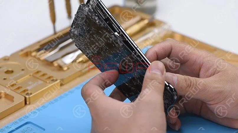
    We can see that the phone has been severely damaged. The screen is shattered and the back glass is broken, the midframe is also deformed.

    We can see that the phone has been severely damaged.

    The screen is shattered and the back glass is broken, the midframe is also deformed.

    Let’s remove the display assembly, the Face ID parts and the rear camera look just fine.

    The motherboard also looks fine too.
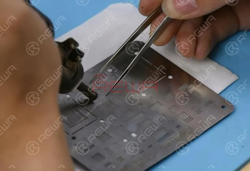
    However, The battery is severely deformed.
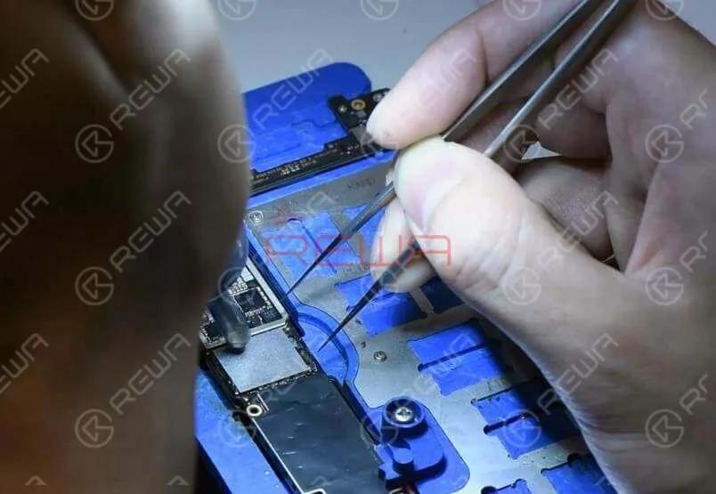
    Test

    Get a new display assembly installed

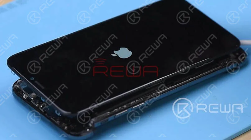
    Get a new display assembly installed, and then connect the battery connector with the DC Power Supply.

    The phone turns on normally, but the touch screen is unresponsive.

    Observe the motherboard carefully, we can see there is an obvious gap between the third space PCB and the lower layer.

    Beside the lower layer is badly deformed. Depending on the motherboard’s condition, we need to swap the lower layer.

    Jumping Wire

    jumping wires

    But let’s fix the upper layer first, clean bonding pads around the edge with Solder Wick.

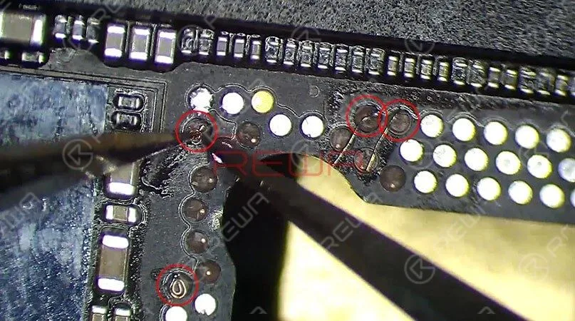
    There are several pads have come off the board.

    We need to treat them by jumping wires.

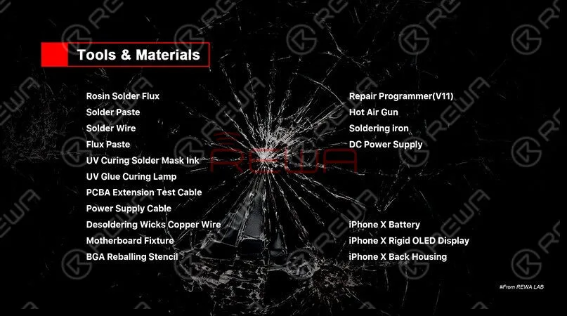
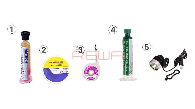
    Here are the tools we recommend for jumping wires:
    1.BGA Flux Paste 2.Solder Wire Kit 3.Desoldering Wick 4.UV Curable Solder Mask 5.USB Ultraviolet Light UV Glue Curing Lamp

    1.BGA Flux Paste

    2.Solder Wire Kit

    3.Desoldering Wick

    4.UV Curable Solder Mask

    5.USB Ultraviolet Light UV Glue Curing Lamp

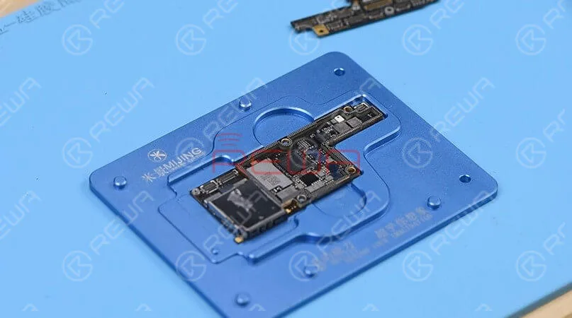
    Attach a known good lower layer to the test fixture and then attach the upper layer.

    Get the display assembly connected.

    Running test, we can found that the phone turns on normally and the touch function is also normal.

    Judging by this, the touch issue is caused by the lower layer.

    Board Swap

    Since the lower layer is badly deformed, we need to transplant baseband CPU, baseband EEPROM and the NFC chip on the original lower layer to a new lower layer.

    For more details, please check out the video below:

    After board swap, we should running test again by using Test Fixture.

    Connect the battery connector with the DC Power Supply.

    Then get the motherboard powered on with tweezers.

    Here we can find IMEI serial number and modem firmware which indicates that the lower layer swap has been completed successfully.

    Motherboard Recombination

    Motherboard Recombination
    repair tool kit

    Next thing we do is to solder the two layers together.

    Here are the following steps:

    Attach the new lower layer to the specialized reballing mold.

    Cover the new lower layer with the matched reballing stencil.

    Smear some low-temp Solder Paste on the stencil.

    remove the reballing stencil carefully.

    Continue to place the new lower layer onto the heating platform.

    Waiting for the solder paste melting, solder balls start to shape up.

    Waiting for the lower layer to cool for 10 minutes.

    Apply BGA Paste Flux to the third space PCB, get the upper layer in position.

    Heat for 1 minute on the heating platform at 160 degrees.

    With the upper layer sinking and Paste Flux flowing, the two layers have been soldered together successfully.

    Wait for the double-stacked motherboard to cool for 5 minutes.

    True Tone Restoration

    True Tone Restoration

    After we finish repairing the motherboard, it’s time to transplant parts.

    REWA has years of experience on providing wholesale services upon an extensive range of electronic related products covering mobile phone spare parts and replacement battery.

    We adhere to the principle of ” Quality Above All ” through the whole producing and testing processes. Here are some of our selected products:

    iPhone X Rigid OLED Display

    iPhone X LCD Display 

    iPhone X Battery Replacement

    iPhone X Back Glass Cover

    Next we will fix the True Tone of the new display.

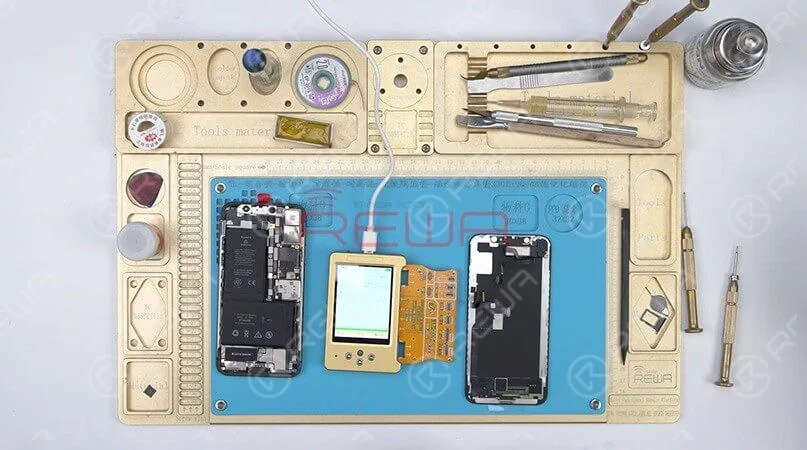
    Connect the original screen with the display extended module, read data of the original screen with the True Tone repair programmer.

    Once done, connect the new screen with the display extended module.

    Write stored data of the original screen to the new screen.

    Wi-Fi Unbinding
    Wi-Fi Unbinding

    Wi-Fi Unbinding

    Beacuse we didn’t deal with the Wi-Fi IC on motherboard, the Wi-Fi switch cannot be toggled.

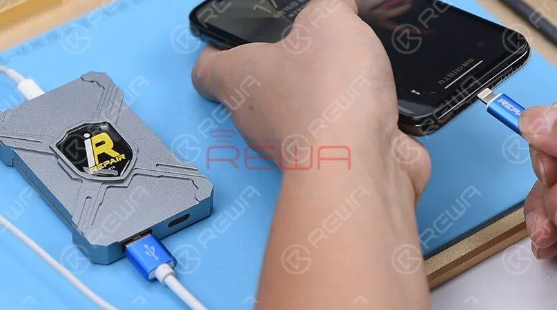
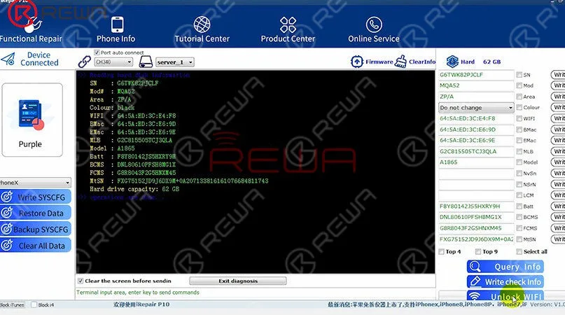
    Here’s a tool we recommend which named iRepair DFU Box.

    Connect it to the computer, then connect the phone with the box.

    Put the phone into DFU mode, then running the software.

    Once finished, the WiFi switch is back to normal.
    rewa academy

    The iPhone X has been restored successfully after our hard work.

    Repair a mobile phone is just like performing phone surgery.

    You need to analyze the problem and then solve the problem step by step.

    The repair process requires not only professional theoretical knowledge but also proficient handwork skills.

    Start your learning journey with REWA ACADEMY now!Preview this course:iPhone Logic Board Repair Handwork Course

  • The Impact of COVID-19 on the Global Repair Business

    The Impact of COVID-19 on the Global Repair Business

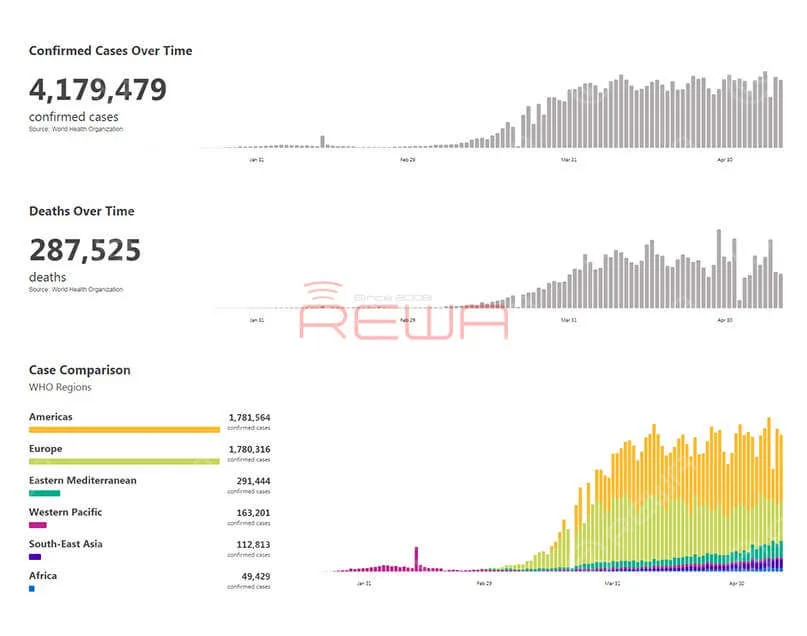
    The coronavirus(COVID-19), the unpreditcable Black Swan, now is sweeping across the world and the real economy has been hit hard.

    As for the mobile phone repair industry, the COVID-19 has also brought negative impacts on all related subjects. Businesses are shutting down.

    Employees are unable to work on-site.

    The productivity of home working can be threatened.

    Supply is in shortage and logistics networks have been thrown into disarray.

    Companies respond with pay cuts and staff reduction plans… What is even more terrifying is that this is only the beginning of the nightmare.
    The Global Repair Business in Pandemic
    The Global Repair Business in Pandemic

    Source: World Health Organization

    For repair shops around the world, some can still open but operate with a sharp decline in performance, resulting in increased losses since they cannot enjoy government subsidies.

    As for repair shops enjoying government subsidies in some countries, their stores are closed by the government and the subsidy from the Government still cannot cover the operating costs and therefore are eager to resume store operations.

    REWA has exchanged views with different mobile phone repairers around the world on the current situation.  How the current epidemic affected their work & life?

    The Global Repair Business in Pandemic

    Jesse from SoCalDigital Repair gave his opinion that the pandemic did not harm his business.

    Otherwise he had gain more iPad repair work because people stuck at home. He had purchase UVC sanitize station to sanitize every devices comes in and taking the necessary by caution.

    However, Our friend Fei from Hong Kong are facing a tough challenge.

    Since the social protest last year, many repair shops have gone out of business.

    Due to the epidemic, his business has fallen off a cliff.

    Now he is trying to use Facebook appoinment to save his business.What measures are they prepare to take to deal with this difficult situation?
    The Global Repair Business in Pandemic
    The Global Repair Business in Pandemic

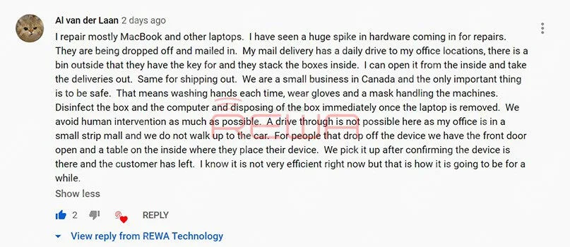
    Source: REWA Technology YouTube

    Some YouTube fans share their strategies with REWA.

    Meanwhile the owner of 911gadgets, Adrian, told us they are not prepared for this situation. Fortunately, they are allowed to continue doing business in central business in the state of California.

    They plan to reduced expenditure or maybe come open a drive-thru repair shop during the pandemic.

    The Global Repair Business in Pandemic

    Luis from Rdx Mobile México believed that crises generate opportunities and this is a great opportunity to diversify and grow their business. Now they doing succcesful home delivery.

    REWA response to the COVID-19  

    Since the outbreak of the epidemic, REWA has taken a series of actions.

    First of all, REWA started home-office and online communication mode, therefore most of the work has been transferred online very quickly.

    Secondly, for employees who must work on-site, REWA have purchased over 30 days stock of epidemic prevention goods, even with a higher price than normal to ensure the safety of our employees.

    Then, in order to meet customers’ online learning demand during the outbreak.

    We launched the REWA Academy. Just in the trial running, it has gained over 300 registration and more than 5000 broadcasting.

    Last but not the least, we also take the initiative to stay in communication with our clients and updates on the progress of the epidemic.

    At the request of our client, we have organized a number of qualified epidemic prevention supplies such as face masks, gloves, thermometer, isolation gown and so on.

    REWA’s view on the global repair business  

    The repair industry will experience a brief blowout growth, because of suppressed demand during the outbreak and pullback in demand before the epidemic can be fully contained within the next 1-2 years.

    As the impact of the initial round of the outbreak eases, repair demand will pick up gradually in May and recover to the previous levels by the end of 2020. Here are the main reasons:

    Take China for example, after people wake up from the panic of the pandemic, they will shift their focus more on economy and social activities.

    Then all the businesses will recover gradually according to the intensity of demand.

    In the first half of the year, global mobile phone shipments fell sharply and the launch of 5G smartphones also get delayed.

    Therefore, consumers who planned to change a new phone are now more likely to keep the old device longer.

    As the global economy is under recession and the power of consumption is weakening, repair your broken phone or buy a used one supposed to be a more economic option for people.

    Unlike the development of other consumer services, the growth of the cellphone repair market seems to be more resilient during the economic downturn.

    This might be a relieved message for us at this hard moment.

    For more interviews, click on the video below to watch

  • Fix iPhone 8 Plus WiFi Not Working | 3-Step-Guide

    Fix iPhone 8 Plus WiFi Not Working | 3-Step-Guide

    In most cases, iPhone grayed-out WiFi switch issue is caused by damage of the WiFi module. And we need to replace the WiFi module to fix the problem.

    What’s more, the WiFi module is bound up with WiFi address stored in the NAND flash chip.

    When replacing the WiFi module, there is one indispensable step as WiFi unbinding.

    How to successfully replace the WiFi module and complete WiFi unbinding in four steps? Follow our repair guide now!

    Problem

    Press the power button to turn on the phone.

    The phone turns on normally.

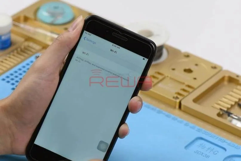
    Go to Settings>WiFi. The WiFi switch cannot be toggled.
    Press the power button to turn on the phone. The phone turns on normally. Go to Settings>WiFi. The WiFi switch cannot be toggled.

    Take apart the phone and remove the display assembly.

    Disconnect the battery and take out the logic board. Then tear off the shielding sticker.

    Diagnosis

    The first thing we do is to check working conditions of the WiFi module.

    Run diode mode measurement of the three rails of power supply.

    Nothing goes wrong.

    Judging by this, WiFi relevant circuits have not open-circuited or short-circuited.
    The first thing we do is to check working conditions of the WiFi module. Run diode mode measurement of the three rails of power supply. Nothing goes wrong. Judging by this, WiFi relevant circuits have not open-circuited or short-circuited.

    Continue to measure the working voltage of the WiFi module.

    Connect the battery connector with the DC Power Supply and short Pin 8 of J4300 to the ground with tweezers.

    The system will then detect power button press.

    Switch the Multimeter to the voltage mode and run voltage measurement of the three rails of power supply.

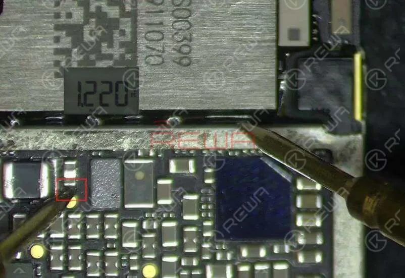
    The measured voltage value of SR_LVX_W is 1.22V, which is abnormal. Normal voltage value should be 1.35V.
    Continue to measure the working voltage of the WiFi module. Connect the battery connector with the DC Power Supply and short Pin 8 of J4300 to the ground with tweezers. The system will then detect power button press. Switch the Multimeter to the voltage mode and run voltage measurement of the three rails of power supply. The measured voltage value of SR_LVX_W is 1.22V, which is abnormal. Normal voltage value should be 1.35V.

    SR_LVX_W is the internal power supply circuit of the WiFi module.

    The abnormal voltage value indicates that the WiFi module has malfunctioned.

    So we need to replace with a new WiFi module.

    Troubleshooting

    Attach the logic board to the PCB Holder.

    Remove black adhesive around the WiFi module.

    Then heat with the Hot Air Gun and pry up the WiFi module with the Sculpture Knife.

    Continue to apply some Paste Flux to the bonding pad.

    And then some middle-temperature solder paste.

    Heat with the Soldering Iron to neutralize the melting temperature on the bonding pad and clean the bonding pad with rosin soaked Solder Wick.

    Clean with PCB Cleaner afterwards.
    Continue to apply some Paste Flux to the bonding pad. And then some middle-temperature solder paste. Heat with the Soldering Iron to neutralize the melting temperature on the bonding pad and clean the bonding pad with rosin soaked Solder Wick. Clean with PCB Cleaner afterwards.

    Note 

    The WiFi module is bound up with WiFi address stored in the NAND flash chip.

    When replacing the WiFi module, here we have one indispensable step as WiFi unbinding.

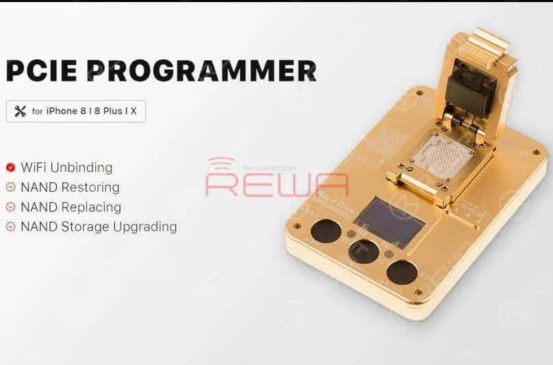
    A PCIE programmer is needed in this step.

    PCIE NAND Flash Memory Chip Programmer For iPhone8/8 Plus/X
    The WiFi module is bound up with WiFi address stored in the NAND flash chip. When replacing the WiFi module, here we have one indispensable step as WiFi unbinding. A PCIE programmer is needed in this step.PCIE NAND Flash Memory Chip Programmer For iPhone8/8 Plus/X

    WiFi Unbinding

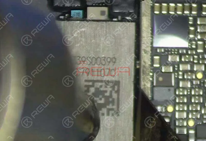
    Heat with the QUICK 990AD Hot Air Gun to remove black adhesive around the NAND flash chip.

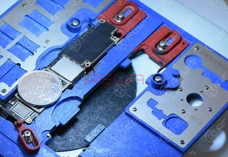
    Since there are multiple components around the NAND flash chip, to protect these components from high-temperature damage, we need to provide heat insulation by placing a coin.
    Heat with the QUICK 990AD Hot Air Gun to remove black adhesive around the NAND flash chip. Since there are multiple components around the NAND flash chip, to protect these components from high-temperature damage, we need to provide heat insulation by placing a coin.

    Once the NAND flash chip has been removed, continue to apply some Paste Flux to the bonding pad and then some middle-temperature solder paste.

    Heat with the Soldering Iron to neutralize the melting temperature on the bonding pad.

    Continue to apply Paste Flux to the detached NAND flash chip and clean the NAND flash chip with the Soldering Iron.

    Place the NAND flash chip into the PCIE Programmer and run the software to complete WiFi unbinding. Once done, take out the NAND flash chip.
    Continue to apply Paste Flux to the detached NAND flash chip and clean the NAND flash chip with the Soldering Iron. Place the NAND flash chip into the PCIE Programmer and run the software to complete WiFi unbinding. Once done, take out the NAND flash chip.

    NAND Reballing

    Next, we need to reball the NAND flash chip.

    Get the BGA Reballing Stencil well aligned with the chip.

    Smear Soldering Paste evenly on the BGA reballing stencil and then heat evenly with the QUICK 990AD Hot Air Gun so that all solder balls can solidify completely.
    Next, we need to reball the NAND flash chip. Get the BGA Reballing Stencil well aligned with the chip. Smear Soldering Paste evenly on the BGA reballing stencil and then heat evenly with the QUICK 990AD Hot Air Gun so that all solder balls can solidify completely.

    Once done, separate the chip from the BGA reballing stencil and clean the NAND flash chip with PCB Cleaner afterwards.

    Chip Soldering

    Now we can solder the NAND flash chip and a new WiFi module onto the board.

    Apply some Paste Flux to the bonding pad.

    Get the NAND flash chip in position.

    Make sure you put it in the right direction.

    Solder with the QUICK 990AD Hot Air Gun.

    Now we can solder the NAND flash chip and a new WiFi module onto the board.Apply some Paste Flux to the bonding pad. Get the NAND flash chip in position. Make sure you put it in the right direction. Solder with the QUICK 990AD Hot Air Gun.

    Continue to apply Paste Flux to the bonding pad of the WiFi module and get a new WiFi module in position. Solder with the QUICK 990AD Hot Air Gun afterwards.

    Reassemble And Test

    Now we can assemble the phone and test. Get the logic board and display assembly installed. Connect the battery and press the power button.

    The phone turns on normally.

    Now we can assemble the phone and test. Get the logic board and display assembly installed. Connect the battery and press the power button . The phone turns on normally.

    Go to Settings>WiFi. The WiFi switch is back to normal. Networks in range can be picked normally. Fault cleared.

    Tools Used

    Hot Air Gun Rework Station – 990AD

    Integrated Repair Platform

    Digital Multimeter

    Communication Maintenance Power Supply

    Electron Microscope 

    PCIE NAND Flash Memory Chip Programmer For iPhone8/8 Plus/X

    Free Schematic Software: Refox

    Visit our online shop for more parts and tools.

    You can also visit REWA YouTube Channel to check our video and learn how to repair the iPhone 8 plus wifi not working issue step by step.

  • Troubleshooting A Dead iPhone CPU Repair

    Troubleshooting A Dead iPhone CPU Repair

    The CPU of mobile phones functions much like the brain of our body, making it a critical component.

    When it comes to mobile phone repair, addressing CPU issues can be quite complex.

    In this article, we will explore how to troubleshoot and repair a common problem with the iPhone 7 not turning on, attributed to pseudo soldering of the CPU.

    Problem

    1. No Response When Turning On the Phone

      • Press the power button, but there’s no response.
    2. Power Supply Test

      • Disassemble the phone.
      • Connect the phone to the DC Power Supply.
      • Press the power button.
      • The current pointer remains static at 50mA-60mA.
      • Connect the phone to a computer; the device cannot be recognized, suggesting USB IC or logic board power supply issues.


    Diagnosis

    To diagnose and potentially resolve the issue:

    1. Testing Power Supply

      • Remove the logic board.
      • Connect the battery connector to the DC Power Supply.
      • Test power button functionality.
      • Measure the 16 rails of the logic board power supply, ensuring the values are within normal ranges.
    2. Replacing USB IC

      • If power supply measurements are normal, replace the USB IC.
      • Attach the logic board to the PCB holder.
      • Carefully remove part of the shield plate.
      • Detach the USB IC using a Hot Air Gun.
      • Clean the bonding pad.
      • Solder a new USB IC and test; if the problem persists, proceed to troubleshooting the CPU.

    Troubleshooting

    Upon identifying CPU-related issues:

    1. Re-soldering the CPU

      • Remove the shield plate with a Hot Air Gun.
      • Apply high-temperature tape to protect nearby components.
      • Carefully detach the CPU from the board using a Hot Air Gun.
      • Clean the bonding pad and remove the solder from the CPU.
    2. Reballing the CPU

      • Position the BGA Reballing Stencil.
      • Apply Solder Paste evenly on the stencil.
      • Heat the solder balls evenly with a Hot Air Gun.
      • Allow the CPU to cool for 2 minutes.
      • Apply BGA Paste Flux to the bonding pad.
      • Position the re-balled CPU and solder it with a Hot Air Gun.
      • Clean with PCB Cleaner.

    Reassemble and Test

    Now that the CPU-related issue has been addressed:

    1. Reassembly

      • Install the logic board and the display assembly.
      • Connect the battery and press the power button.
    2. Testing

      • The phone should turn on normally.
      • Run a function test to ensure that all components are functioning correctly.

    Conclusion

    By following these steps, you can successfully troubleshoot and repair CPU-related issues in mobile phones. In this specific case, the iPhone 7 not turning on due to pseudo soldering of the CPU, our comprehensive process has resolved the problem, allowing the device to function as expected.

    Tools Used

    Free Schematic Software: Refox

    Visit our online shop for more parts and tools.

    You can also visit REWA YouTube Channel to check our video and learn how to repair a dead iPhone step by step.

  • iPhone 7 Plus Touch ID Repair: Fix Broken Home Button Cable

    iPhone 7 Plus Touch ID Repair: Fix Broken Home Button Cable

    For iPhone 7-8P, 80% of Touch ID issues are caused by broken home button cable and we can fix the problem by jumping wires on the two layers of wires on the home button cable respectively. Which is very difficult especially when the bottom layer comes with many wires. And that’s when we bring you this new solution in our iPhone 7 Plus Touch ID repair blog today. With the help of the iPhone 7-8P Home Button Repair Socket Cable, we can fix the Touch ID problem in a safe and efficient way.

    Tips: the home button cable is fragile and therefore professional operation is needed. For those who have no repair skills, please look before you leap.

    Malfunction

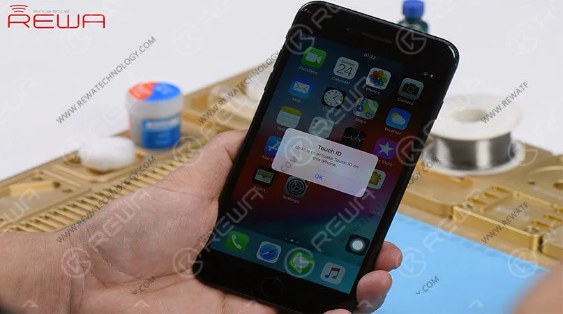
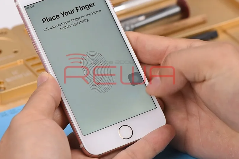
    Press the power button to turn on the phone. The phone turns on normally. However, there is an alert saying “Unable to activate Touch ID on this iPhone. Try to press the home button. The home button is also unresponsive.

    Press the power button to turn on the phone. The phone turns on normally. However, there is an alert saying "Unable to activate Touch ID on this iPhone. Try to press the home button. The home button is also unresponsive.

    Go to Settings > Touch ID & Passcode. The option ‘Add a Fingerprint’ is grayed out. Judging by this, home button relevant circuit or home button cable has malfunctioned.

    Diagnosing

    Take apart the phone and remove the display assembly. Run diode mode measurement of the home button connector. The measured value is normal. Which indicates that home button relevant circuit is also normal. And the home button issue has nothing to do with the logic board.

    Take apart the phone and remove the display assembly. Run diode mode measurement of the home button connector. The measured value is normal. Which indicates that home button relevant circuit is also normal. And the home button issue has nothing to do with the logic board.

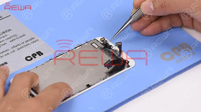
    Next, we need to check the home button cable. Disconnect the home button cable. We can see that the home button cable nearby the socket is broken.

    Troubleshooting

    Judging by this, when installing/detaching the home button cable, rough operation of the technician led to the broken cable and resulted in the Touch ID not working problem. And for iPhone 7/7P/8/8P, 80% of Touch ID issues are caused by broken home button cable. We can fix the broken cable by jumping wires.

    Judging by this, when installing/detaching the home button cable, rough operation of the technician led to the broken cable and resulted in the Touch ID not working problem. And for iPhone 7/7P/8/8P, 80% of Touch ID issues are caused by broken home button cable. We can fix the broken cable by jumping wires.

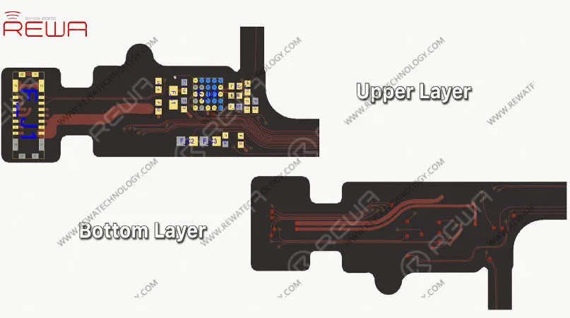
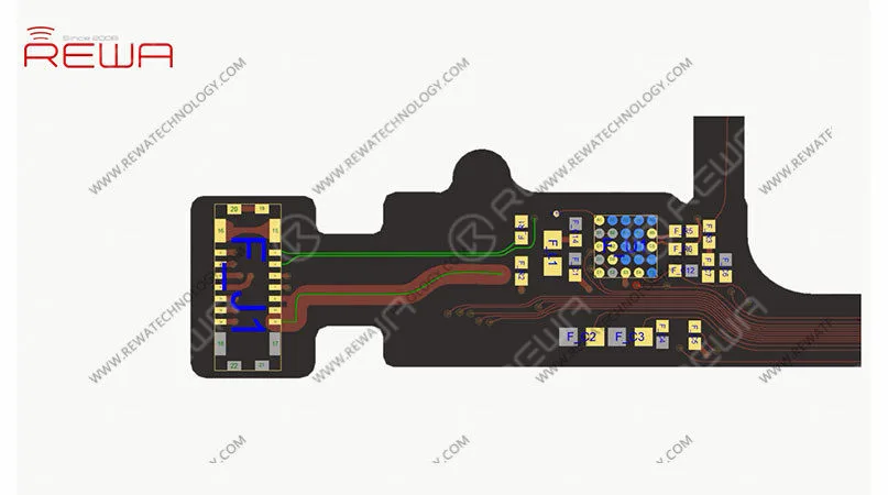
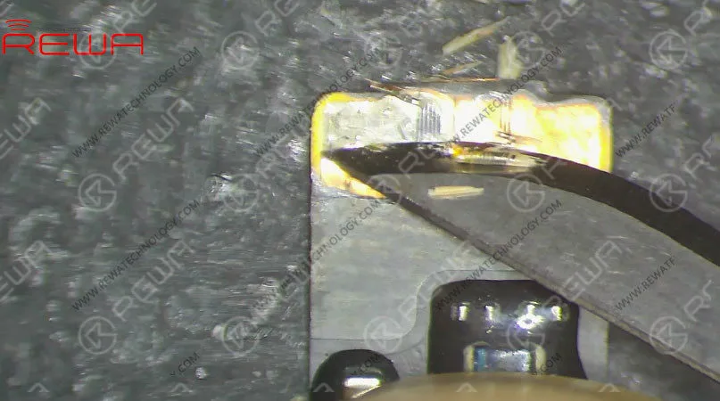
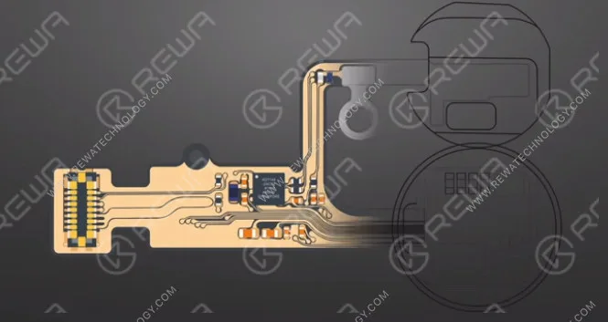
    Also, there are two layers of wires on the home button cable. The bottom layer comes with more wires than the upper layer. When repairing the broken cable, the traditional way is to jump wires on the two layers respectively. Which is difficult and the home button cable might also be damaged. And that’s when we bring you this safe and efficient solution today. We can repair the broken cable by soldering the bottom layer of wires to the iPhone 7-8P Home Button Repair Socket Cable and joining up the upper layer of wires by jumping wires.

    How To Fix iPhone 7 Plus Touch ID Not Working - Broken Home Button Cable Repair

    Please be noted that the home button cable can be easily damaged, here we also need a specialized Sculpture Knife to complete the work

    Broken Home Button Cable Repair

    Step 1

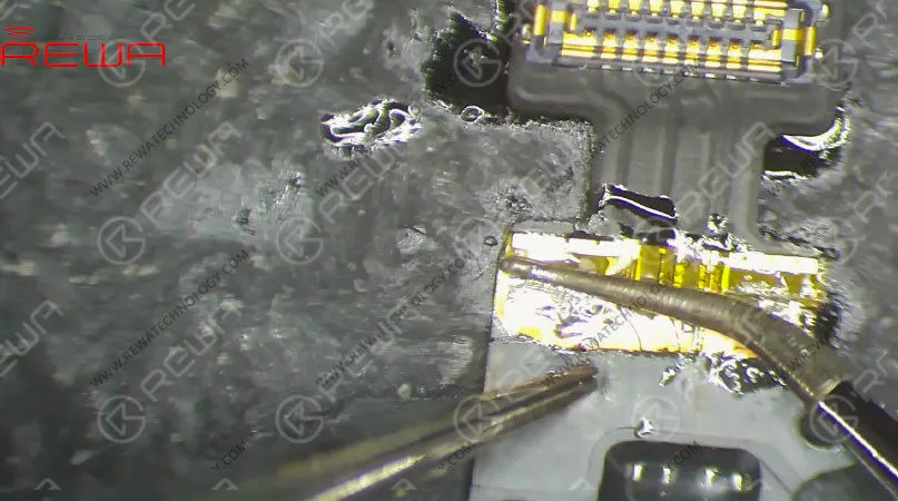
    Secure the home button cable with the double-sided tape. Cut off the broken cable along with the socket. Then slice open the insulating coating on the cable.

    Step 2

    Heat with the Helical Wind Hot Air Gun for 5 seconds. Scrape off the insulating coating and then wires on the upper layer with Sculpture Knife. Clean with PCB Cleaner soaked cotton ball afterwards.

    Heat with the Helical Wind Hot Air Gun for 5 seconds. Scrape off the insulating coating and then wires on the upper layer with Sculpture Knife. Clean with PCB Cleaner soaked cotton ball afterwards.

    Step 3

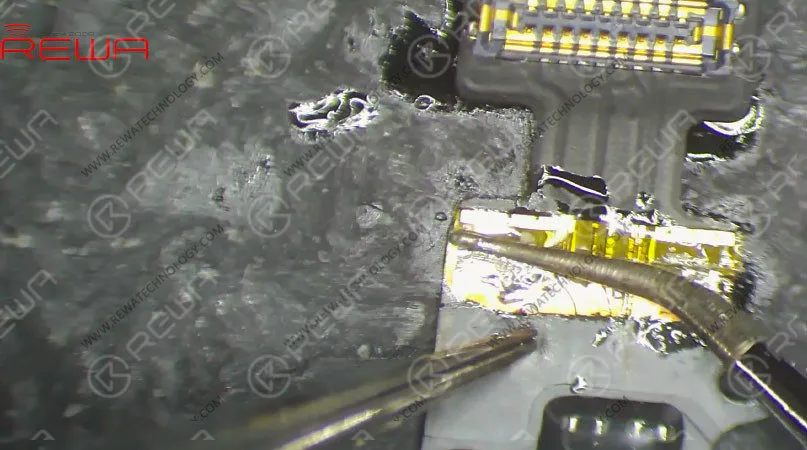
    Cut off the needless part of the Home Button Repair Socket Cable. Apply some solder paste and paste flux to the bottom layer. Apply the home button repair socket cable to the right position. Solder carefully with the Soldering Iron. Once done, clean with PCB Cleaner soaked cotton ball.

    Cut off the needless part of the Home Button Repair Socket Cable. Apply some solder paste and paste flux to the bottom layer. Apply the home button repair socket cable to the right position. Solder carefully with the Soldering Iron. Once done, clean with PCB Cleaner soaked cotton ball.

    Step 4

    Now we need to solidify the soldered area. Apply some UV Curable Solder Mask to the soldered area. Then solidify the cable under UV Dryer Lamp for 5 minutes.

    Step 5

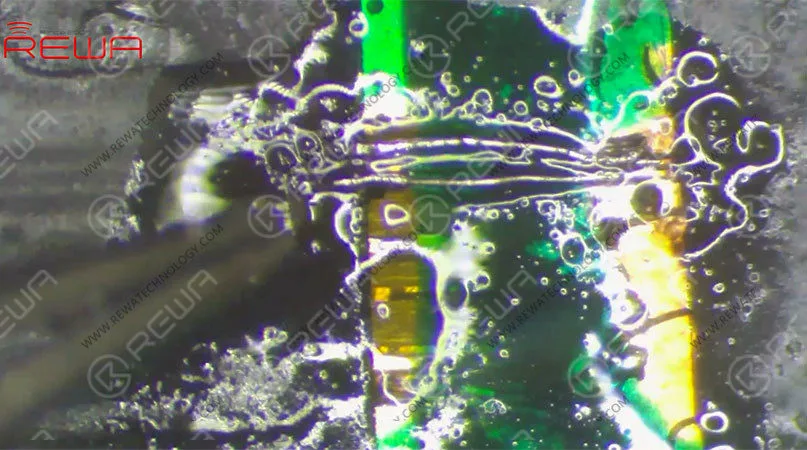
    Next, let’s join up the upper layer of wires by jumping wires. Apply some paste flux and solder paste first. Here we need 0.02mm solder tinned enamelled wire. Solder the wire to the corresponding position on the upper layer one by one. Once done, apply some UV Curable Solder Mask. Then solidify the cable under UV Dryer Lamp for 5 minutes.

    Next, let’s join up the upper layer of wires by jumping wires. Apply some paste flux and solder paste first. Here we need 0.02mm solder tinned enamelled wire. Solder the wire to the corresponding position on the upper layer one by one. Once done, apply some UV Curable Solder Mask. Then solidify the cable under UV Dryer Lamp for 5 minutes.

    Test

    Now we can assemble the phone and test. Get the home button cable installed. Get the display assembly installed and battery connected. Press the power button to turn on the phone. The phone turns on normally.

    Now we can assemble the phone and test. Get the home button cable installed. Get the display assembly installed and battery connected. Press the power button to turn on the phone. The phone turns on normally.

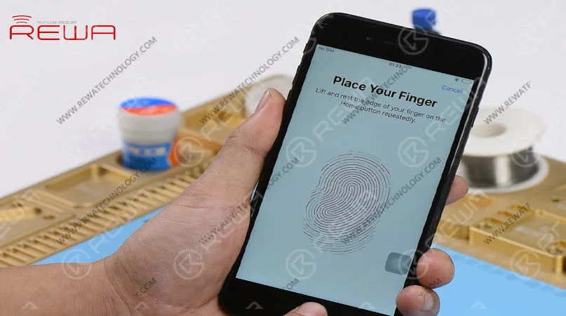
    Go to Settings > Touch ID & Passcode. The option ‘Add a Fingerprint’ is back to normal. Try to set up Touch ID on the phone. With Touch ID set up successfully on the phone, Touch ID function is also normal. The home button is also back to normal Warm tips: get the phone full assembled after confirmation of fault clearance.

    You can also visit REWA Youtube Channel to check our video of iPhone 7 Plus Touch ID Not Working – Broken Home Button Cable Repair.

  • How to Fix Samsung Galaxy S9 Plus No Network Connection: A Complete Troubleshooting Guide

    How to Fix Samsung Galaxy S9 Plus No Network Connection: A Complete Troubleshooting Guide

    The Samsung Galaxy S9 Plus is a fantastic smartphone with numerous hardware upgrades compared to its predecessor, the Galaxy S8. It features a powerful Snapdragon 845 processor, 4GB RAM, and a vibrant 5.8-inch AMOLED display. However, some users have encountered network connection issues, making it difficult to use mobile data, send messages, or make calls. In this article, we will guide you through the troubleshooting steps to fix the Samsung Galaxy S9 Plus no network connection problem.

    What Does No Service Mean?

    If you’re experiencing network connectivity issues on your Samsung Galaxy S9 Plus, check if you can:

    • Use mobile data
    • Send text messages
    • Make or receive calls
    • See the network signal bars on the top-right of the screen

    If the signal bars are missing or if there’s a small “x” next to the signal icon, it means there’s no network service.

    Steps to Follow:

    1. Reset Network Settings

    If your Samsung Galaxy S9 Plus won’t connect to mobile data, follow these steps:

    1. Go to Settings → General Management → Reset.
    2. Select Reset Network Settings.

    Once the reset is complete, check if the issue persists.

    2. Restart Your Device

    If resetting the network settings doesn’t solve the problem, restart your phone:

    1. Power off your device.
    2. Wait for a few seconds, then turn it back on.

    After rebooting, check if the network connection issue is resolved.

    3. Manually Select Network Mode

    If your Samsung S9 Plus still experiences connectivity problems, manually adjust the network settings:

    1. Go to Settings → Connections → Mobile Networks.
    2. Select Network Mode and switch it to GSM/WCDMA (disabling LTE).
    3. Next, choose Network Operators → Search Networks.
    4. The phone will search for nearby networks (this may take 1-2 minutes). Once completed, select your carrier from the list.

    This step helps you manually reconnect your phone to a network, bypassing any LTE-related issues.

    4. Try a Different SIM Card

    Sometimes, a faulty SIM card may be the cause of network issues. To check if this is the case:

    1. Insert a known working SIM card from another device into your Samsung Galaxy S9 Plus.
    2. If the phone successfully retrieves the signal, the issue is likely with the original SIM card.
    3. If the problem persists, the issue may be linked to your carrier or your phone’s network settings.

    What Happens When You Reset Network Settings?

    Resetting your network settings will revert all wireless connections to their default factory state. This includes:

    • Deletion of stored Wi-Fi networks
    • Removal of paired Bluetooth devices
    • Re-enabling background data sync
    • Network selection mode reverting to automatic

    To reset the network settings:

    1. On the Home Screen, swipe up to open the Apps tray.
    2. Go to Settings → General Management → Reset → Reset Network Settings.
    3. Tap RESET SETTINGS, and if prompted, enter your PIN.
    4. Tap RESET SETTINGS again to confirm.

    Once completed, a confirmation window will appear.

    Another Solution: Factory Reset

    If the issue still persists after trying the above steps, a factory reset may resolve the problem. Follow these steps carefully:

    1. Power off your phone.
    2. Press and hold the Volume Up and Bixby keys, then press and hold the Power key.
    3. When the green Android logo appears, release all keys.
    4. Use the Volume Down key to navigate to Wipe data/factory reset and press the Power button to select.
    5. Confirm by pressing Yes – this will delete all user data.
    6. After the reset, you’ll see Reboot system now. Press the Power key to restart your device.

    Conclusion:

    Following these steps should help you resolve the Samsung Galaxy S9 Plus no network connection problem. If the issue persists even after resetting network settings or performing a factory reset, it’s best to consult a professional technician or visit a Samsung service center. Alternatively, you can seek help from a Mobile App Development Company if you’re experiencing issues with mobile apps causing connectivity problems.

  • Troubleshooting Guide: Fix iPhone 7/7P Home Button Not Working

    Troubleshooting Guide: Fix iPhone 7/7P Home Button Not Working

    Return-to-home functionality failure is a common issue of iPhone 7/7P and the problem is usually related to the U10 chip on the home button cable.

    And that’s what our iPhone 7 Home Button not working troubleshooting blog is about today.

    Tip 1: The home button cable is fragile and therefore professional operation is needed. For those who have no repair skills, please look before you leap.

    Step 1 TEST

    1. Press the home button to unlock the phone.

    2. Open an APP and press the home button. It fails to return back to the home screen.

    3. Double-press the home button again, there is also no response.

    4. Long-press the home button and Siri is also not launched.

    5. Check out Touch ID Setting. It is working normally.

    6. Judging by this, that means the return-to-home functionality fails. This is a common issue of the iPhone 7/7P about home button.

    Step 2 Troubleshooting

    How To Fix iPhone 7/7P Home Button Not Working

    The return-to-home functionality of home buttons on iPhone 7/7P/8/8P is supported by the U10 chip on the home button cable.

    Tips 2: The home button cable is secured by double-sided adhesive underneath.

    How To Fix iPhone 7/7P Home Button Not Working

    1. Heat up before removing the home button cable.

    2. Attach the detached home button cable to the PCB Holder.

    3. Secure the cable with High-temperature tape.

    How To Fix iPhone 7/7P Home Button Not Working

    Tips 3: The home button cable is fragile. Please control the operating temperature of the Hot Air Gun and the Soldering Iron during the repair work. This is to protect the home button cable from high-temperature damage.

    How To Fix iPhone 7/7P Home Button Not Working

    4. Heat with the Hot Air Gun to remove sealing adhesive around U10 chip.

    5. Detach the U10 chip from the home button cable and clean its bonding pad with Soldering Iron afterwards.

    6. Apply some UV Curable Solder Mask to the exposed area for insulation protection before soldering the chip. Then solidify the home button cable under UV Dryer Lamp for 15 minutes.

    How To Fix iPhone 7/7P Home Button Not Working

    7. Solder a new U10 chip afterwards.

    8. Get the home button cable installed.

    9. Turn on the phone and test.

    10. Touch ID works normally. The return-to-home functionality is also back to normal. For details of this case, please check out the YouTube Video below.

    For tools and parts used in the video, please click the link below to get, visit REWA online shop for more.

  • 3 In 1 Rework Station For Mobile Phone Repair

    3 In 1 Rework Station For Mobile Phone Repair

    Hot Air Guns, Soldering Irons and DC Power Supplies are essential tools for electronic maintenance engineers.

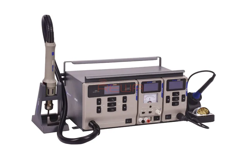
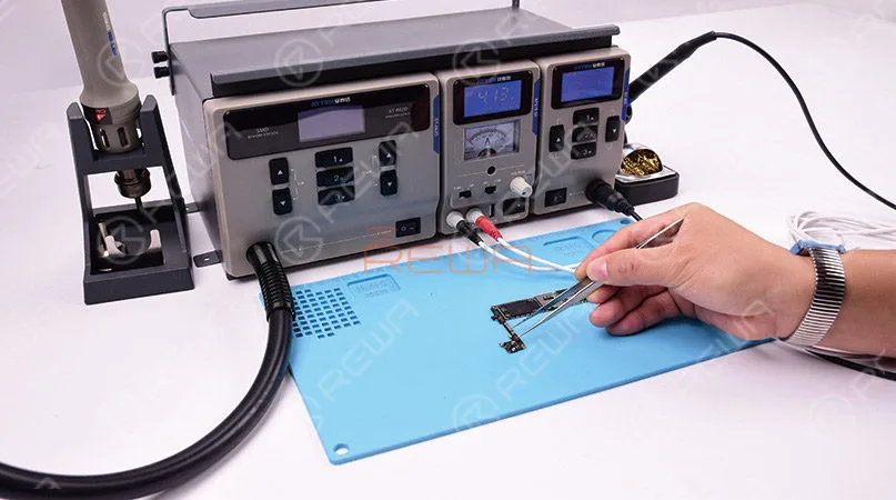
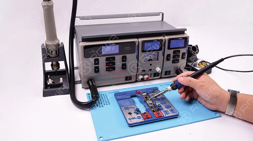
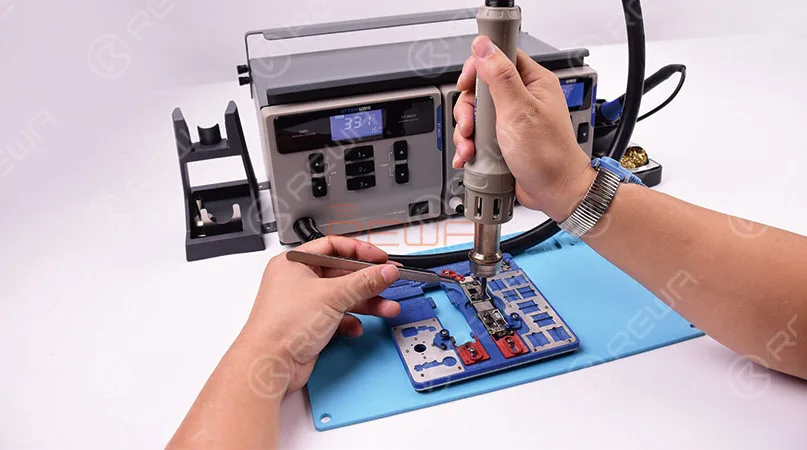
    In today’s blog, we will introduce a 3 in 1 Rework Station for Mobile Phone Repair. It is not only space-saving but also cost-effective.

    And therefore it is the best partner for repair beginners.

    The 3 In 1 Rework Station for Mobile Phone Repair includes a ST-862D Hot Air Station, a ST-965 Soldering Station and an APS15-3A Power Supply.

    Let’s check their features one by one.

    3 In 1 Rework Station For Mobile Phone Repair

    Power Supply APS15-3A

    A DC power supply is used to provide DC power for logic board repairing and booting test.

    With the built-in current/voltage reading display, it can also be used as a reference for fault-finding.

    FEATURES

    • Perfect short protection and over-current protection & Overheating Protection.
    • Micro-controller Unit features low noise, high stability and low ripple.
    • Built-in locking and alarm setting can effectively avoid mistaken operation.

    3 In 1 Rework Station For Mobile Phone Repair

    Soldering Iron ST-965

    A soldering iron is used to solder the spare parts on the green-colored PCB (Printed Circuit Board) of mobile phones.

    These soldered parts may get disconnected, lose contacts with the PCB or simply come out over time.

    They may also come out due to shock or jerk due to falling down.

    Therefore you need to solder the parts back again with a soldering iron.

    FEATURES

    • Temperature calibration & alarm setting.
    • LED display for real-time temperature & working status monitoring.
    • Auto sleep/switch-off function to highly extend Product life.
    • CH 1/2/3 preset temperature for a fast switch.

    3 In 1 Rework Station For Mobile Phone Repair

    Hot Air Gun ST-862

    It is one of the most frequently used tools in mobile phone repair.

    From replacing charging ports to removing various capacitors and resistors, a hot air gun is a must.

    FEATURES

    • Conversion between vertical wind and helical wind.
    • LED display for real-time temperature & working status monitoring.
    • Auto sleep, safe and power saving.
    • Precise temperature control, and constant set temperature.

    The 3 In 1 Rework Station for Mobile Phone Repair is available now.

    You can place an order for the whole set or buy a separate one on REWA ONLINE SHOP.

    For bulk ordering, please contact REWA Account Manager to get an exclusive discount.

  • Essential Tools for Double-stacked Motherboard Repair

    Essential Tools for Double-stacked Motherboard Repair

    iPhone series from  iPhone X to the newest iPhone 11 Pro Max comes with the double-stacked motherboard.

    Therefore, it is important for repair shops to improve double-stacked motherboard repair techniques. REWA highly recommends the following 3 must-have tools for iPhone double-stacked motherboard repair.

    Check it now! Double-stacked Motherboard Repair Steps There are 4 steps to repair the double-stacked motherboard as follows:

    Step 1: Motherboard Separating

    When repairing the logic board of the iPhone series before iPhone X, we can remove/solder components with the help of the Hot Air Gun.

    However, with the motherboards of iPhone X and later models being double-stacked, the Hot Air Gun fails to heat the third space PCB evenly due to the large range.

    Hereby we recommend this Specialized Heating platform for your double-stacked motherboard repair.

    A Must-have Tool For Motherboard Separating During Double-stacked Motherboard Repair – 3 in 1 Heating Platform For iPhone X/XS/XS Max

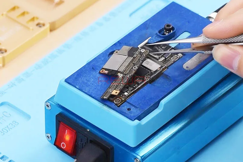
    You will need the Motherboard Disassemble Platform Main Unit For iPhone – SS-T12A and Motherboard Disassemble Platform Heating Groove For iPhone X/XS/XS Max – T12A – X3.

    The 3 in 1 Heating Platform For iPhone X/XS/XS Max is suitable for iPhone X/XS/XS Max motherboard separating, CPU and other components removing. The temperature range is 100-280℃.

    Tips: Traditional Hot Air Gun features high requirements for temperature control.

    Therefore, any carelessness may result in solder joint falling-off or bridging that leads to not turning on of the motherboard or other issues.

    3 Must-have Tools For Double-stacked Motherboard Repair

    Step 2: Diagnosing & Trouble Shooting

    During the repairing of the double-stacked motherboard, there is always a time when we need to test the motherboard completely.

    And to do that, we need to solder the two layers back together.

    Now, with this third space PCB Test Fixture, we can test the motherboard completely without recombining the two layers.

    A Must-have Tool For Diagnosing&Troubleshooting During Double-stacked Motherboard Repair – 2 in 1 Test Fixture For iPhone XS/XS Max and Test Fixture For iPhone X With the help of the test fixture, repair technicians can narrow down fault possibilities when troubleshooting the motherboard.

    It can not only improve repair efficiency but also bring less damage to the motherboard.

    3 Must-have Tools For Double-stacked Motherboard Repair

    Step 3: Lower Layer Reballing

    We need to solder the two layers back together after troubleshooting.

    A Must-have Tool For Lower Layer Reballing During Double-stacked Motherboard Repair – 3 in 1 BGA Reballing Fixture For iPhone X/XS/XS Max

    The 3 in 1 BGA Reballing Fixture can complete your reballing work easily and efficiently.

    With the reballing stencil fitting perfectly with the lower layer, even and full solder balls can be ensured.

    3 Must-have Tools For Double-stacked Motherboard Repair

    Step 4: Motherboard Recombining

    After reballing work. We need to solder the two layers back together.

    Here in this step, we will use the same tool as in the previous motherboard separating process – 3 in 1 Heating Platform For iPhone X/XS/XS Max.

    3 Must-have Tools For Double-stacked Motherboard Repair

    For more details about the iPhone X/XS/XS Max/ 11 Pro/Pro Max Motherboard repair, please check the video below.

    You can also visit REWA YouTube Channel for more videos.

    For iPhone X/XS/XS Max/11 Pro/11 Pro Max motherboard repair kit, please stay tuned to REWA Online Shop.

    Any questions and demands please feel free to contact us: sales@rewatechnology.com

  • iPhone 11 Pro Back Glass Repair

    iPhone 11 Pro Back Glass Repair

    As the most powerful and most advanced iPhone that Apple has ever built, iPhone 11 Pro  is made of a surgical grade stainless steel its back is a single piece of machine glass with an optical PVD coating, adding to the difficulty of repair.

    What’s more, the arrangement of rear cameras of iPhone 11 Pro also greatly increases the difficulty of back glass repair.

    REWA LAB tried different solutions (heating with the Hot Air Gun, separating with the dispergator/freeze assistance) and we were unable to remove the glass around the triple-lens camera safely and efficiently.

    Check our detailed operation on iPhone 11 Pro back glass repair and hope we can enlighten you somehow.

    Scan The 11 Pro Back Glass With Laser

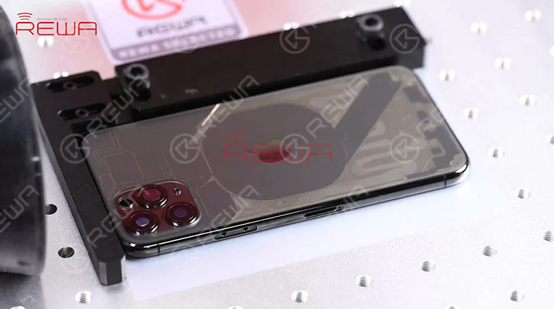
    First of all, place the iPhone 11 Pro back glass under the probe for focusing.

    Then place the iPhone 11 Pro back glass on the operating panel.

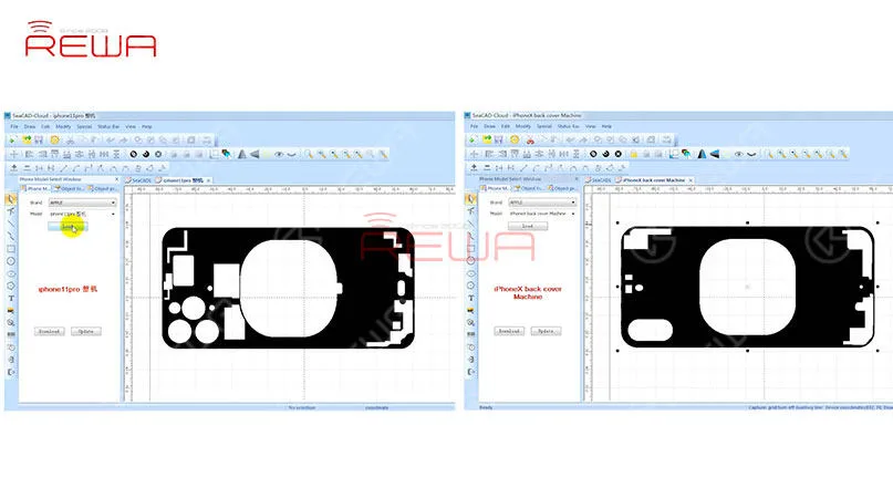
    Choose ‘iPhone 11 Pro’ from the model list and click ‘Load’ to load the drawing.

    The black area on the drawing is the area to be scanned, And the white area is the area to be retained.

    Tips: Compare the two drawings and we can see that different from iPhone X, there are more areas the laser should keep away from when scanning iPhone 11 Pro.
    First of all, place the iPhone 11 Pro back glass under the probe for focusing. Then place the iPhone 11 Pro back glass on the operating panel.   Choose ‘iPhone 11 Pro’ from the model list and click ‘Load’ to load the drawing.   The black area on the drawing is the area to be scanned, And the white area is the area to be retained.   Tips: Compare the two drawings and we can see that different from iPhone X, there are more areas the laser should keep away from when scanning iPhone 11 Pro.

    After loading the drawing of iPhone 11 Pro, adjust the laser light scanning area on the back glass.

    Once finished, get the parameter set and click ‘Mark’ to scan the back glass with the laser light.

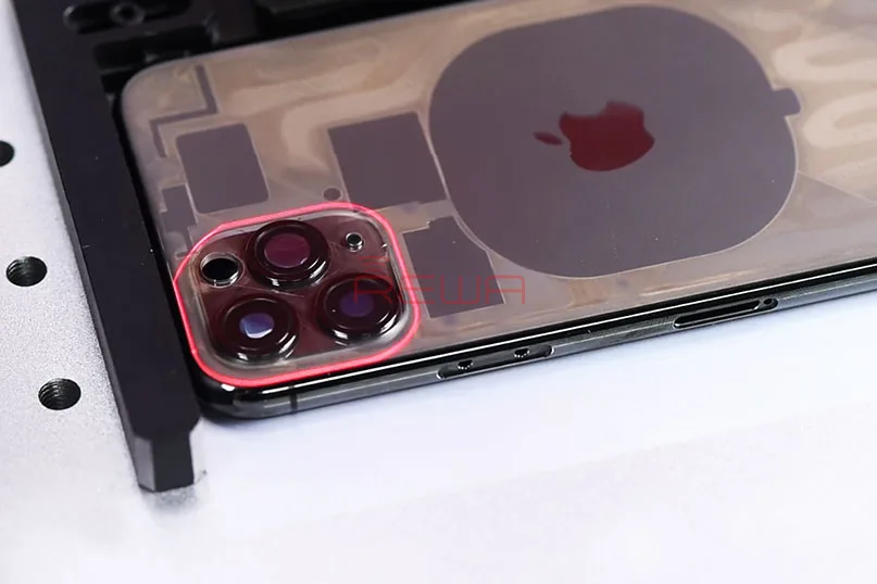
    The back glass becomes transparent after laser scanning.
    After loading the drawing of iPhone 11 Pro, adjust the laser light scanning area on the back glass. Once finished, get the parameter set and click ‘Mark’ to scan the back glass with the laser light. The back glass becomes transparent after laser scanning.

    Scan The Glass Around The Triple-lens Camera With Laser

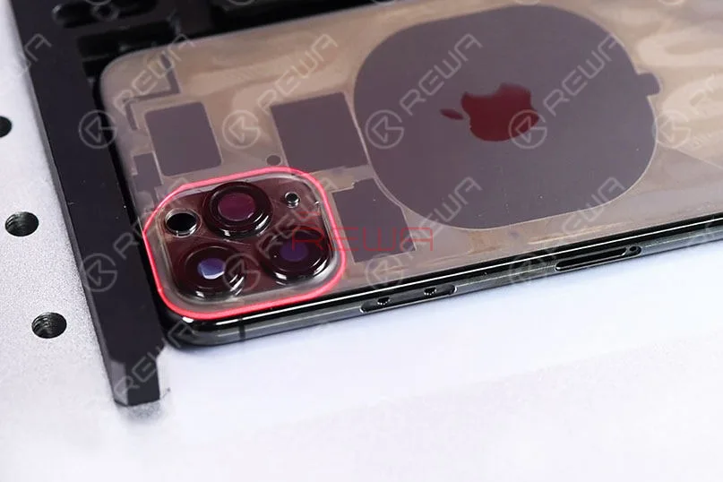
    As you can see, the glass around the triple-lens camera is relatively thick.

    The laser light scanning didn’t work well with the area here.

    After several attempts and experiments, REWA LAB successfully completed a specialized drawing for the triple-lens camera area.

    Scan the triple-lens camera area again with the laser with the help of the drawing.

    The glass around the triple-lens camera also becomes transparent after the second laser scanning.
    Scan the triple-lens camera area again with the laser with the help of the drawing. The glass around the triple-lens camera also becomes transparent after the second laser scanning.

    Separate The Back Glass From The Mid-frame 

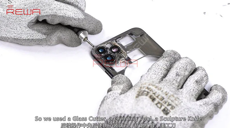
    Now we need to separate the back glass from the mid-frame. The scanned back glass can be separated easily. However, the glass around the triple-lens camera needs further operation. Our commonly used tools failed to remove the glass here, so we used a glass cutter, a grinding tool, a Sculpture Knife and a Cutting Nipper to remove the glass around the triple-lens camera. At the last, once completed, remove residual black adhesive with the Laser Machine.
    Now we need to separate the back glass from the mid-frame. The scanned back glass can be separated easily. However, the glass around the triple-lens camera needs further operation. Our commonly used tools failed to remove the glass here, so we used a glass cutter, a grinding tool, a Sculpture Knife and a Cutting Nipper to remove the glass around the triple-lens camera. At the last, once completed, remove residual black adhesive with the Laser Machine.

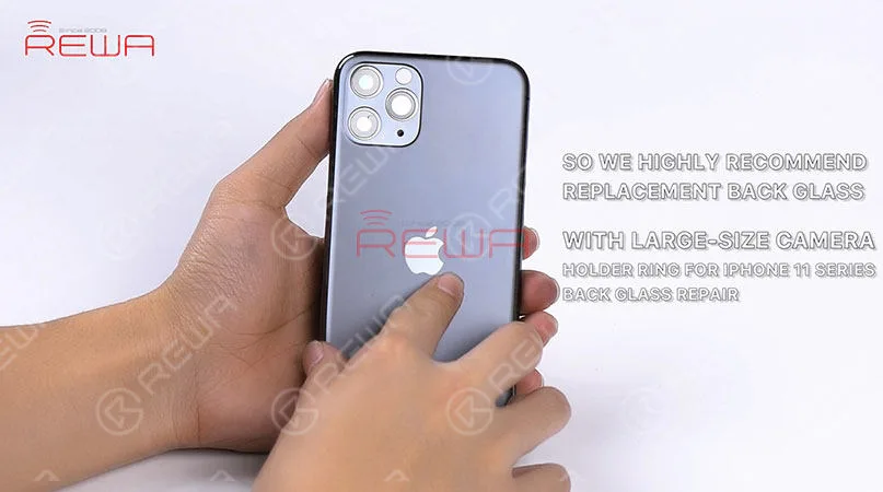
    The camera holder ring of iPhone 11 series is harder and comes with thick inside walls, adding to the difficulty of polishing.

    Meanwhile, the camera lens can also be easily damaged during polishing.

    So we highly recommend replacement back glass with a big camera hole for iPhone 11 series back glass repair.
    The camera holder ring of iPhone 11 series is harder and comes with thick inside walls, adding to the difficulty of polishing. Meanwhile, the camera lens can also be easily damaged during polishing. So we highly recommend replacement back glass with a big camera hole for iPhone 11 series back glass repair.

    Due to the special arrangement of the three cameras of iPhone 11 Pro, the space between the three cameras is also narrow, adding to the difficulty of back glass separating.

    Therefore, the Laser Machine may be the safest and most efficient solution for iPhone 11 Pro back glass repair.

    For more details about the back glass repair of iPhone 11 Pro, please check the video below. You can also visit REWA YouTube Channel for more videos about iPhone 11 series.

    REWA LAB will work hard to provide a better solution for iPhone 11 Pro back glass repair.

    The replacement parts of iPhone 11 series are also coming soon, please stay tuned to REWA Online Shop.