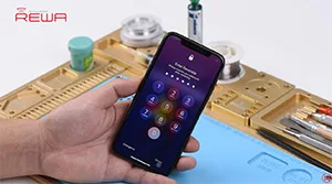
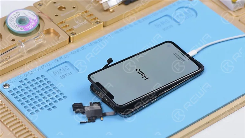
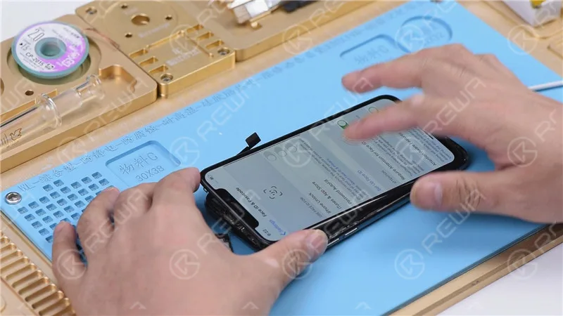
Face ID lets you securely unlock your iPhone, authenticate purchases and sign in to apps all with just a glance. However, due to the vulnerability of the Face ID parts, it can be easily damaged when iPhone X is dropped or during screen replacement, which will result in Face ID failure. Don’t worry. In this video, REWA guides you to fix “Face ID Is Not Available” step by step. Let’s check.
This is also a reminder. Please be careful in your daily use of the phone!
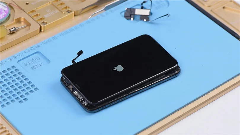
It can be extremely frustrating to find your iPhone stuck on apple logo or iTunes Error 4013. In most cases, this is not a serious issue and a software update can resolve the issue. However, if the software update does not resolve the issue, it may be a hardware issue that requires a more thorough diagnosis and repair.
iPhone Error 4013: Possible Causes
iPhone Error 4013 can occur due to various factors, encompassing both software and hardware components, which contribute to the occurrence of this perplexing error.
Outdated iTunes Version
One of the primary causes of iPhone Error 4013 is an outdated version of iTunes. Since iTunes is crucial for both restoring and updating the device, it is imperative to keep it up to date. A simple and free software update can often resolve this issue, ensuring smooth communication between the iPhone and the computer.
Software Glitches
Random firmware crashes can sometimes lead to iPhone Error 4013. Performing a force restart or hard reset can help overcome these software glitches. By holding down the appropriate buttons, you can initiate a restart that may rectify the error and restore normal functionality.
Hardware Complications
While software issues are common culprits, hardware problems can also trigger iPhone Error 4013. In some cases, sweat or other forms of liquid entering the earpiece can cause a boot loop and lead to this error. Additionally, faulty USB cables, damaged USB ports, or third-party security software can contribute to this frustrating issue.
This blog post will exclusively address hardware problems that can lead to this issue.
Remarque : Please note that this tutorial utilizes an iPhone X for demonstration purposes, although the method can be applied to most iPhone models.
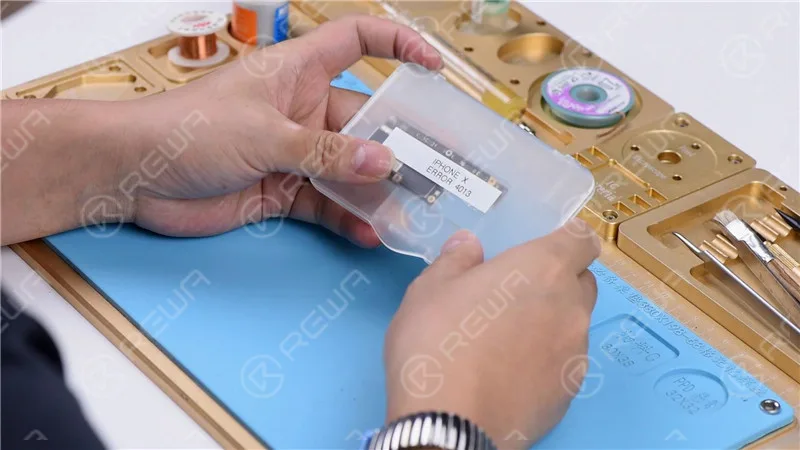
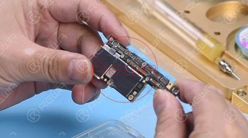
Cosmetic Inspection of the Motherboard
Before diving into any troubleshooting, it’s essential to ensure the motherboard is in optimal condition. Check for any deformities or water damage that might hinder the repair process.
Identifying the Problem
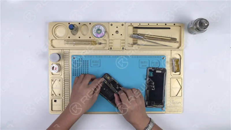
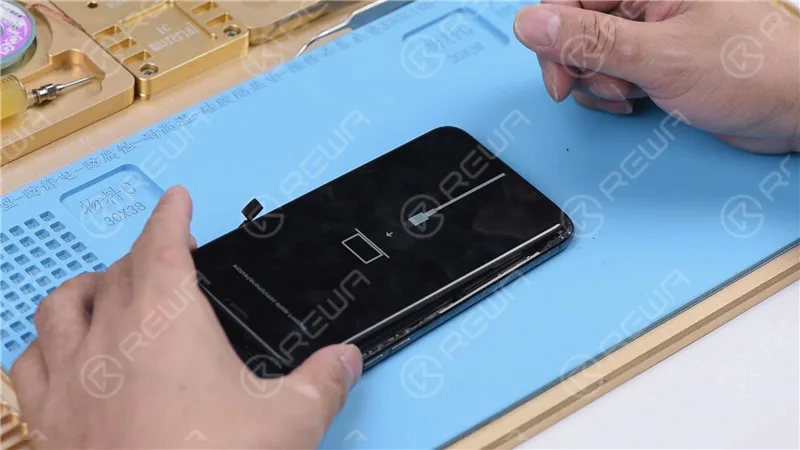
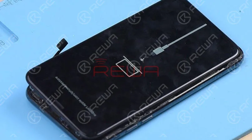
Let’s proceed with the motherboard installation and test it by pressing the power button. However, the phone automatically enters recovery mode, indicating a possible restore failure with the motherboard. As a result, the phone is unable to boot into the system normally.
Restoring the Phone
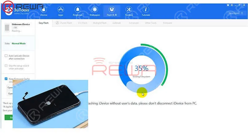
To begin, connect your iPhone X to a computer and initiate the restoration process using 3U Tools. A successful restoration indicates the motherboard is functioning correctly, and your phone can be activated normally.
Diagnosing Further Issues
Successful Restoration
If the phone can be restored successfully and activated, it’s an indication that the motherboard is functioning properly. The issue likely lies elsewhere.
Checking Baseband Info
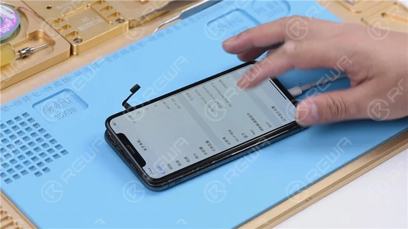
Navigate to Settings>General>About to verify the baseband information, reinforcing the motherboard’s health.
Pinpointing the Issue
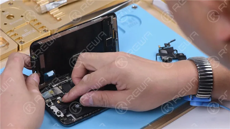
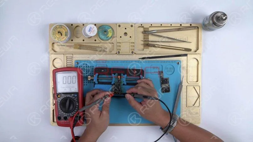
Adding Flex Cables: To narrow down the problem, reattach the earpiece speaker and sensor flex cable along with the front camera flex cable, and attempt to turn on the phone.
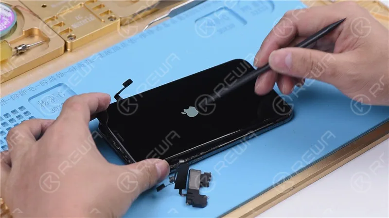
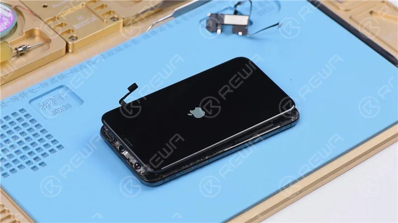
Stuck on Apple Logo: If the phone gets stuck on the Apple logo and restarts, it suggests an issue with the earpiece speaker and sensor flex cable or the front camera flex cable.
Isolating the Problem
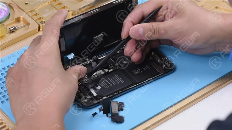
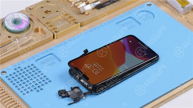
Disconnecting the Earpiece Speaker and Sensor Flex Cable: Remove the earpiece speaker and sensor flex cable, then try to power on the phone. If it turns on normally, the issue is indeed related to these components.
Fixing the Flood Illuminator Module
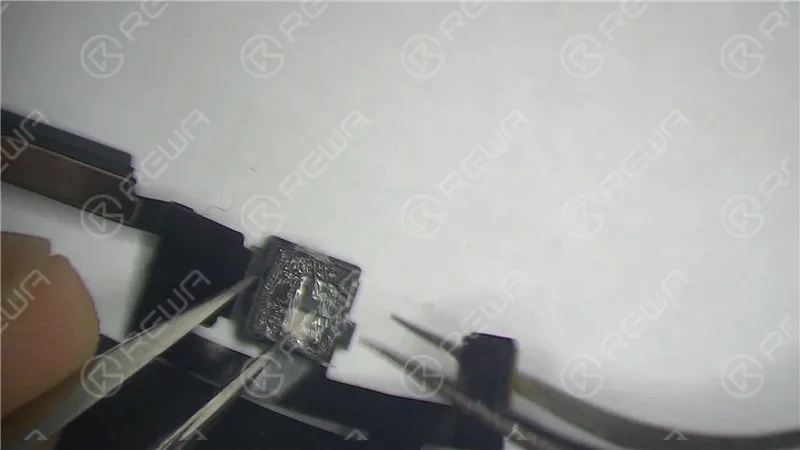
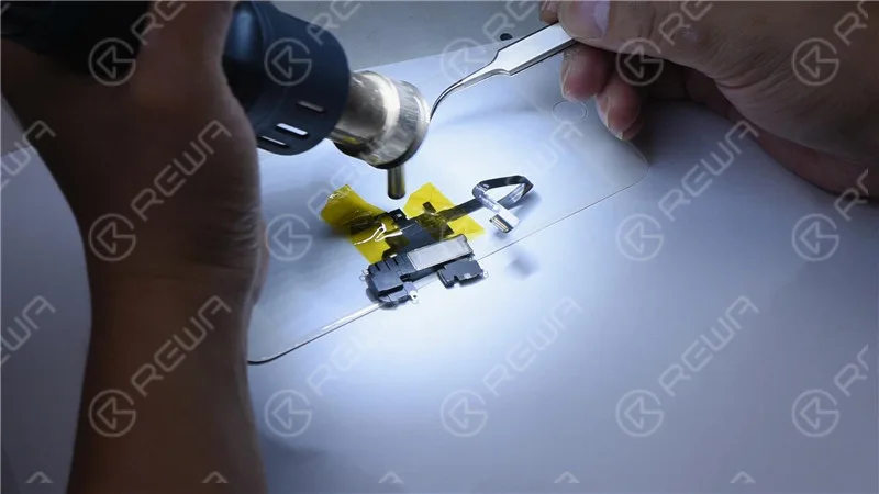
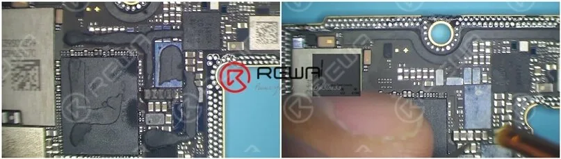
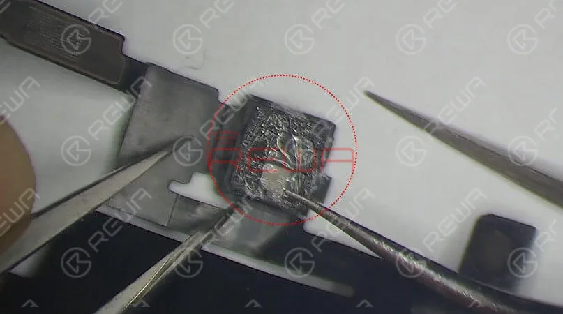
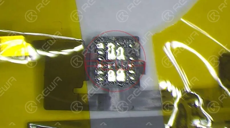
Microscopic Examination: Inspect the Flood illuminator module and identify any mold or corrosion.
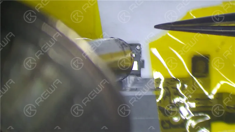
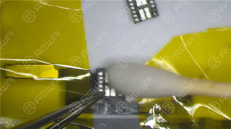
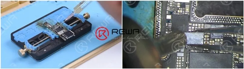
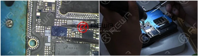
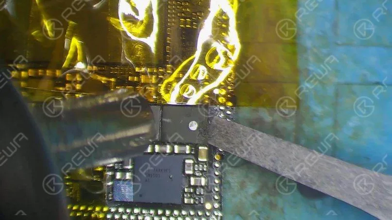
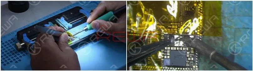
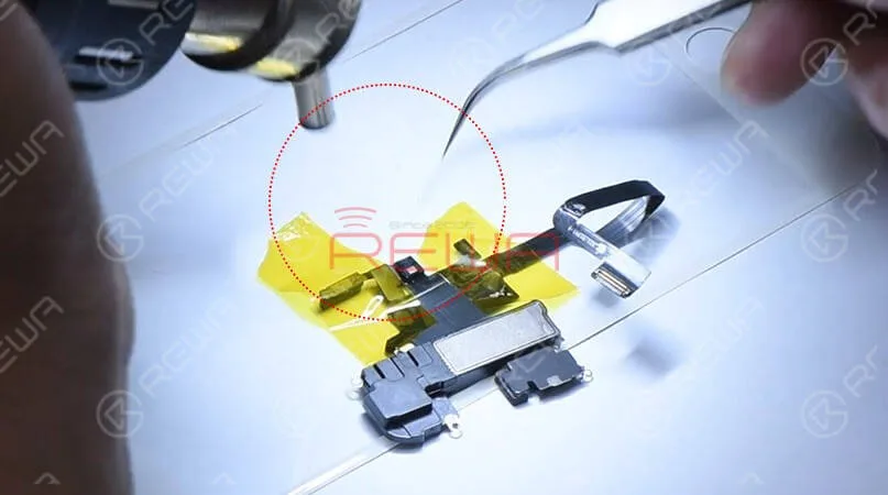
Repairing with High-Temperature Tape: Fix the earpiece speaker and sensor flex cable using high-temperature tape. Heat the affected area with a Hot Air Gun at 320℃ with an air flow of 35. Remove the damaged Flood illuminator module.
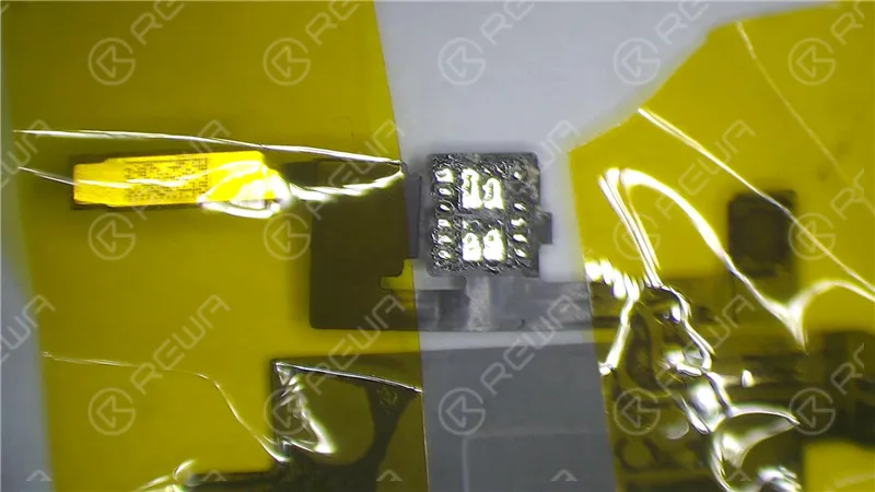
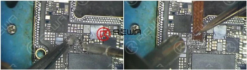
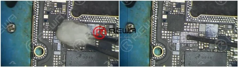
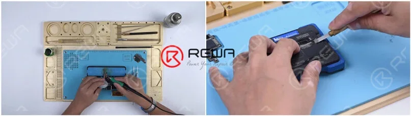
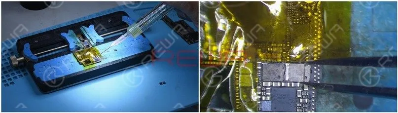
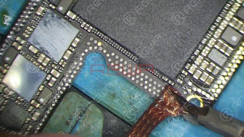
Corroded Bonding Pad: If the bonding pad on the Flood illuminator module is severely corroded, apply paste flux, clean with a soldering iron at 360℃, and reapply medium-temp solder paste. Clean with PCB Cleaner afterward.
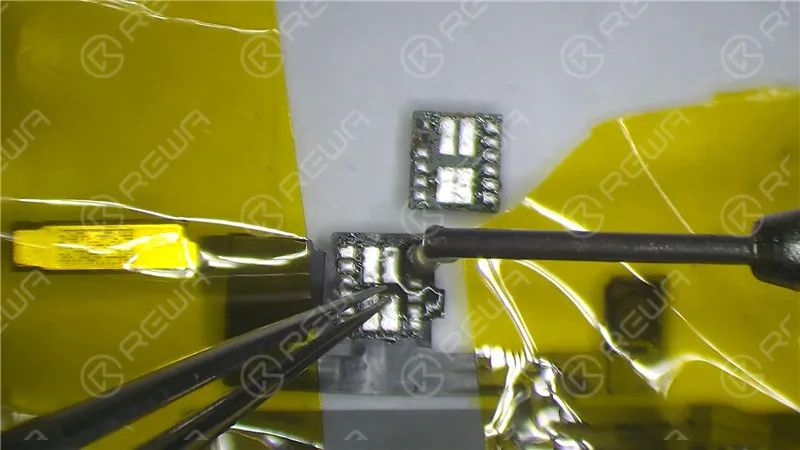
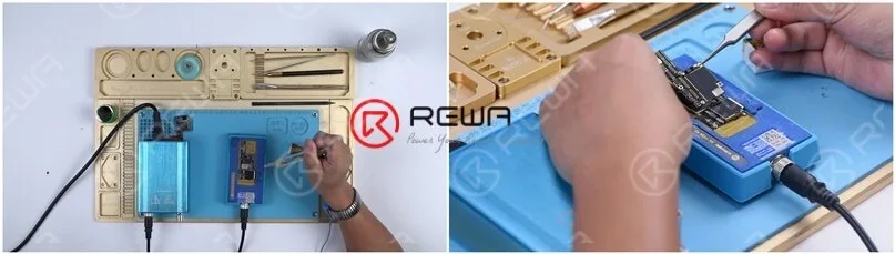
Remontage : Reassemble the Flood illuminator module, applying paste flux and soldering it in place with a Hot Air Gun at 320℃.
Wait for 2 Minutes: Allow the repaired components to settle for two minutes.
Testing and Restoring
Reconnection: Reinstall the earpiece speaker and sensor flex cable, connect the battery, and power on the phone.
Restoring with Components Connected: Since the flex cables were not connected during the previous restoration, restore the iPhone X with both cables connected to ensure Face ID functionality.
Final Verification
Entering DFU Mode: Place the phone in DFU mode and connect it to the computer.
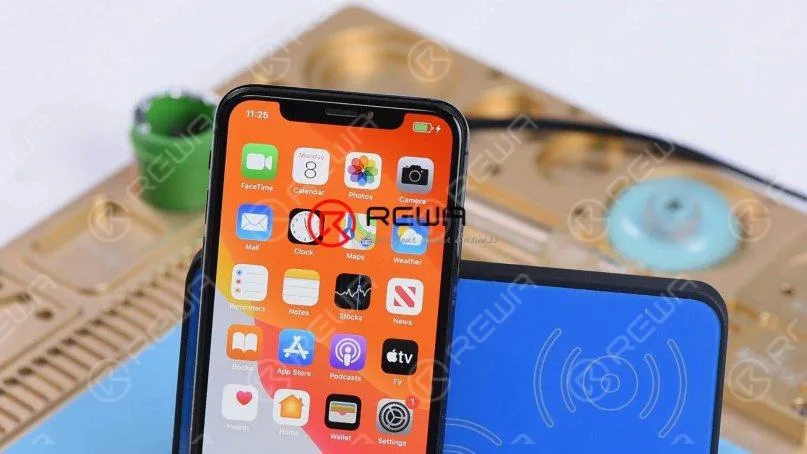
Restoration: Use 3U Tools or similar software to restore the phone. If it completes successfully, and the phone boots into the system and allows for Face ID setup, the issue has been resolved.
Video Guide to Fix iphone stuck on apple logo
Conclusion :
In this comprehensive guide, we have walked through the troubleshooting and repair process for an iPhone X stuck on the Apple logo with iTunes Error 4013. By methodically evaluating each component, from the motherboard to the earpiece speaker and sensor flex cable, we’ve successfully identified and fixed the issue, allowing the phone to function normally once again. For more in-depth repair knowledge, consider visiting Académie REWA.
Bonjour les gars, aujourd'hui nous allons vous guider à travers les astuces de réparation pour le dessoudage&soudage du circuit intégré de charge de l'iPhone X.
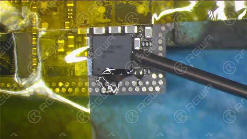
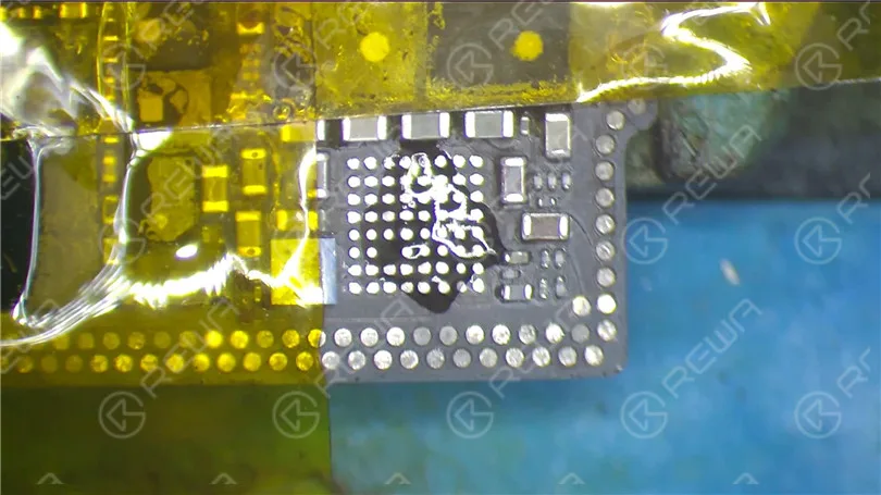
Tout d'abord, collez du ruban adhésif haute température sur les composants situés autour du circuit intégré de charge afin de les protéger contre les pseudo-soudures/ponts pendant l'opération.
Appliquer ensuite un peu de flux en pâte autour du circuit intégré de charge.
Régler la température du QUICK 990 AD Vertical Wind Hot Air Gun à 330℃, flux d'air 3. Maintenir le pistolet à air chaud à une hauteur de 5mm-10mm de l'IC de charge.
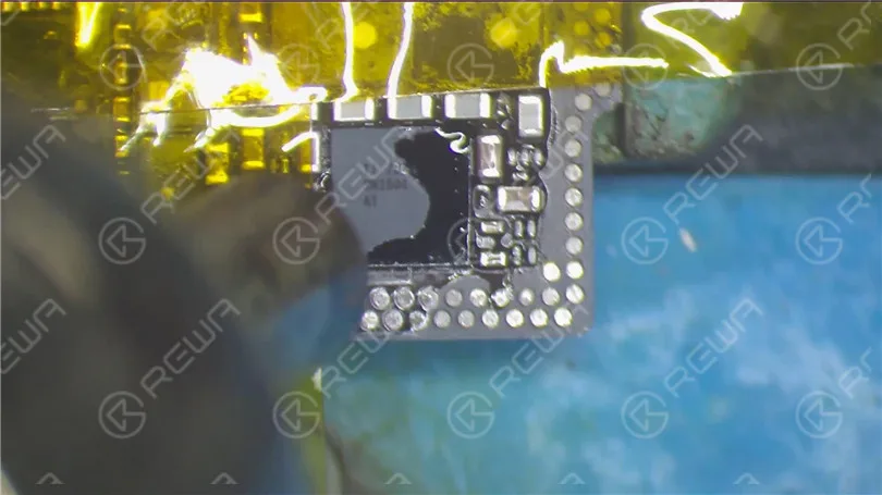
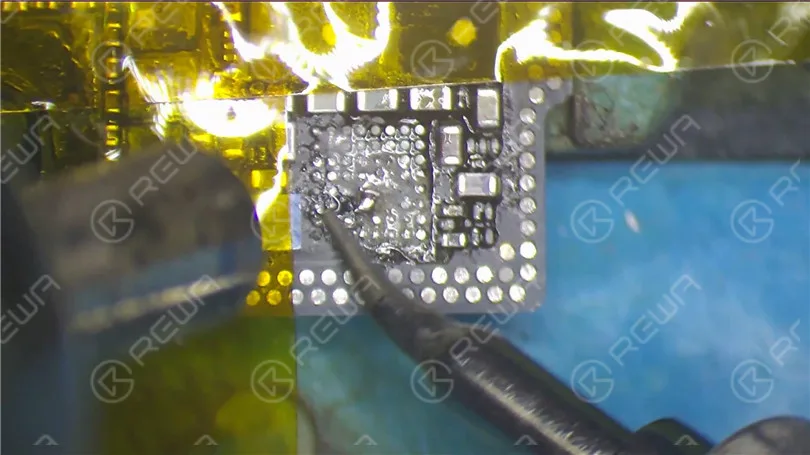
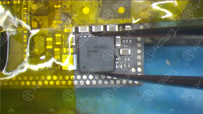
Chauffez pendant environ 15 à 20 secondes, puis retirez le circuit intégré de charge. Conseils : contrôlez la force appliquée lorsque vous soulevez le circuit intégré. Les opérations brutales risquent d'endommager la puce ou le plot de collage.
Continuez à appliquer de la pâte à souder à température moyenne sur le plot de collage. Chauffer avec le pistolet à air chaud QUICK 990 AD à vent vertical à 280℃, débit d'air 3.
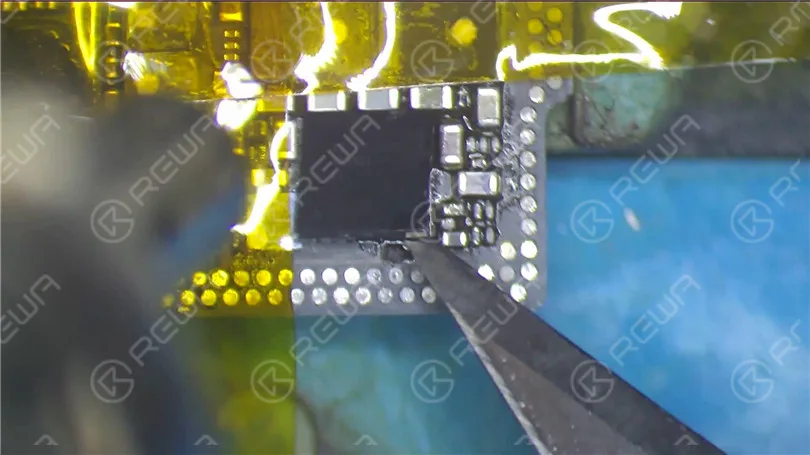
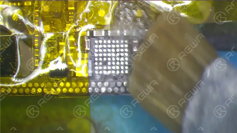
Pendant ce temps, nettoyer les joints de soudure sur le tampon de collage avec le fer à souder à 360℃. Une fois cela fait, nettoyer soigneusement le tampon avec une mèche de soudure imbibée de colophane.
Soyez également prudent dans vos opérations. Des opérations brutales peuvent entraîner une pseudo-soudure/un pontage des composants autour de l'appareil.
Nettoyer ensuite avec le PCB Cleaner.
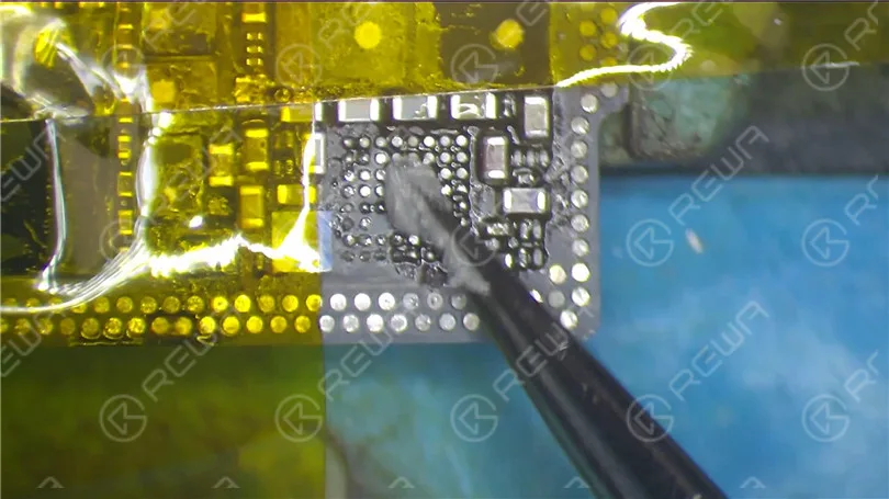
Nous devons maintenant nettoyer les joints de soudure à l'arrière du circuit intégré de charge.
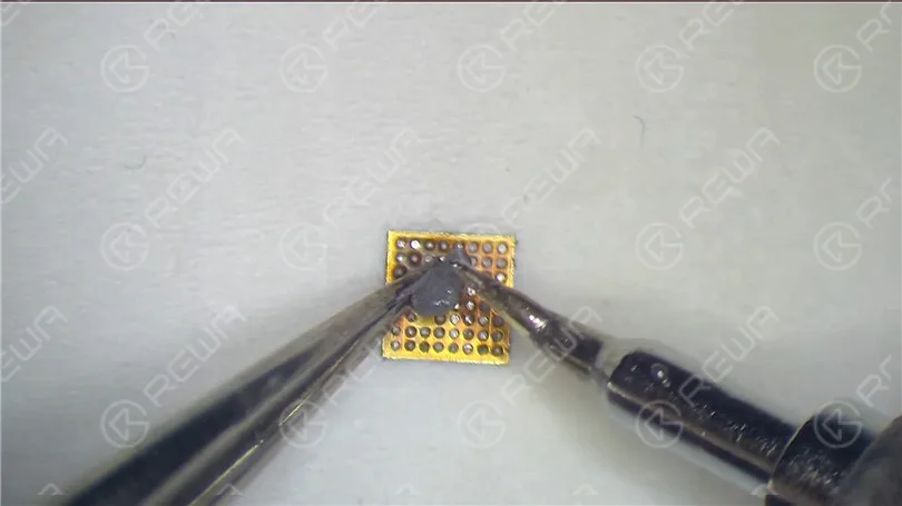
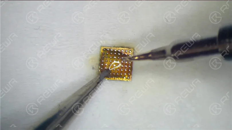
Appliquer de la pâte à souder à température moyenne sur la pastille de collage au dos. Nettoyer la pastille avec un fer à souder à 360℃.
Vous pouvez également appliquer du flux en pâte pour un meilleur nettoyage.
Une fois que c'est fait, nettoyez avec le PCB Cleaner. Astuce : ne soyez pas trop strict avec les joints de soudure sur le pad. Vous pouvez conserver plusieurs joints de soudure afin d'assurer un reballage parfait par la suite.
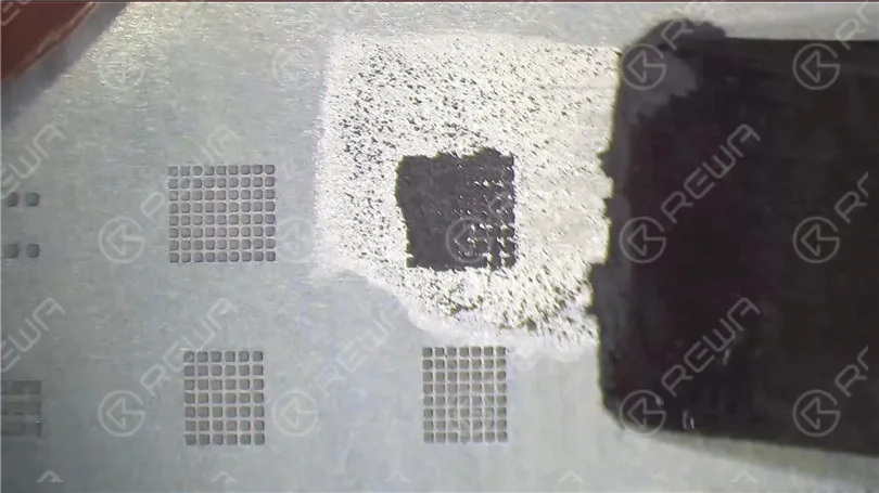
Passons maintenant au processus de reballage. Mettez le pochoir de rebouclage BGA en place. Appliquez de la pâte à souder à température moyenne à l'aide du grattoir pour BGA.
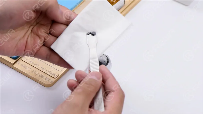
Appliquez ensuite la pâte à souder sur un mouchoir en papier. Cela permet de sécher la pâte à souder en l'enveloppant dans le mouchoir en papier.
Ainsi, la pâte à braser peut être bien préparée pour le rechargement. Une pâte à souder trop humide pourrait provoquer des ponts lors du reballage. Continuez à étaler uniformément la pâte à souder à température moyenne sur le pochoir. Essuyez la pâte à souder superflue avec un chiffon non pelucheux.
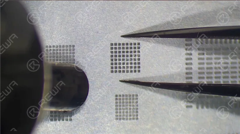
Appliquer une pression sur le pochoir de rebouclage BGA avec une pince à épiler. Chauffer avec le pistolet à air chaud QUICK 990 AD à 300℃, flux d'air 3, afin que toutes les billes de soudure puissent se solidifier complètement.
Conseils : lors du chauffage, le pistolet à air chaud doit s'approcher de loin en près, des bords vers le centre.
Un chauffage concentré peut déformer le pochoir. Le processus de mise en forme des billes de soudure peut également être affecté.
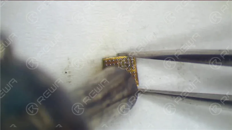
Une fois que c'est fait, laissez refroidir pendant 1 minute. Nettoyez ensuite avec du PCB Cleaner. Séparez délicatement la puce du pochoir à l'aide d'une pince à épiler. Serrez ensuite la puce avec une pince à épiler.
Chauffer à nouveau avec le pistolet à air chaud QUICK 990 AD à 300℃, débit d'air 3, afin d'assurer la formation parfaite des billes de soudure.
Nous pouvons maintenant souder le circuit intégré de charge. Appliquez un peu de flux en pâte sur la pastille de collage.
Placer le circuit intégré de chargement dans la bonne position.
Ne le placez pas dans la mauvaise direction. Souder avec le QUICK 990 AD Vertical Wind Hot Air Gun à 330℃, flux d'air 2. 15s-20s plus tard, avec l'IC sinking et le flux de pâte débordant.
Continuer à chauffer pendant environ 5 secondes. Une fois que c'est fait, nettoyer avec le PCB Cleaner.
N'hésitez pas à visiter Académie REWA pour étudier davantage de techniques et de compétences en matière de réparation de téléphones.
iPhone gets stuck on the Apple logo, which usually means that there is a problem with the operating system or hardware of the phone. Check out our video today and we will show you how to diagnose and fix the problem step by step.
Today we will talk about how to replace iPhone X SIM card reader.
The SIM card reader of iPhone X is soldered with medium-temperature tin, while the middle layer of the motherboard adopts low-temperature tin. Hence we advise you to separate the motherboard before removing the SIM card reader. There are other ICs on the SIM card reader. Besides, a plastic part is also in the middle of the SIM card reader.
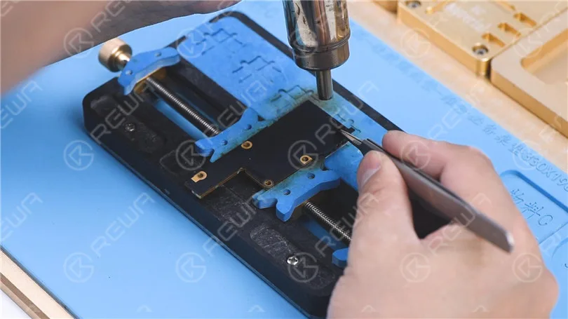
While disassembling and soldering, we need to heat it with rotational air and control the temperature. Attach the motherboard to the PCB Holder. Heat it with Hot Air Gun 240℃ and airflow 7. Tear off the sticker on the back of the motherboard.
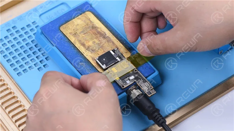
Placez la carte mère sur le Plate-forme de chauffage. We only need to heat the SIM card reader part. Fix the motherboard with high-temperature adhesive. Set the temperature of the Heating Platform to 200℃. Heat the edge of the SIM card reader with Pistolet à air chaud 280℃ and airflow 7.
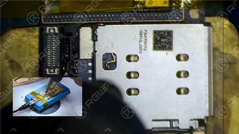
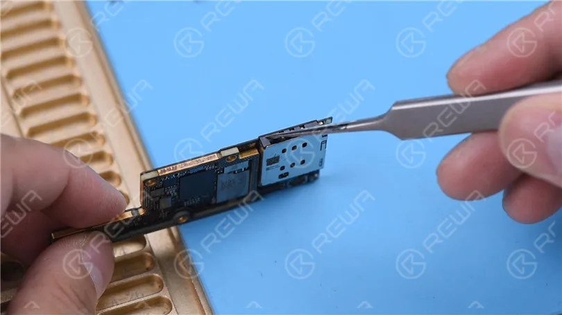
Stir the SIM card reader with tweezers while heating. Remove the SIM card reader when it becomes loose. Please be noted that we need to pick up the SIM card reader in a vertical manner. To avoid damage or malposition of components under the SIM card reader, please do not pry with tweezers. Next, we replace the old SIM card reader with a new one. Apply some Paste Flux to the bonding pad of the SIM card reader. Put the new SIM card reader in position. Keep heating it on the 200℃ Heating Platform. Heat the edge of the SIM card reader evenly with Hot Air Gun 280℃ and airflow 7. Press the SIM card reader gently while heating. Make sure that the SIM card reader is pressing against the PCB.
Turn off the power. Cool the motherboard. Check the SIM card reader soldering. The SIM card reader is pressing against the PCB. Every soldering spot has no pseudo soldering. Solder it again with Soldering Iron if pseudo soldering happens.
Please set the temperature of the Hot Air Gun according to the environment and device brand. The temperature in this article is only for reference.
Veuillez consulter le site Académie REWA to study more iPhone repair knowledge.
Frozen or Touchscreen unresponsive is one of the most commonly seen cases in iPhone repair. Generally speaking, there are two different causes for iPhone x touch screen unresponsive. Malfunction of rails or components on the motherboard. Or touch failure caused by malfunction of the screen, which can be easily fixed by replacing with a new display assembly.
Today, we are teaching you how to rule out and get the problem fixed by starting with simple, then complex.
We don’t know where the problem lies. On screen? Or on the motherboard? So here we use a simple way to make a preliminary judgment first. Replace with a new undamaged screen! If it works fine on this phone board, we can confirm that the problem is related to the screen. As iPhone X screen digitizer assembly is expensive, it’s not that cost-effective for customers to change a new one. So let’s try to fix it. Cosmetic inspection goes first!
We can see that the touch flex cable is not fractured, and the touch connector also looks fine. There is nothing unusual on the bonding area between the touch flex cable and the display flex cable. Judging by this, the fault is probably caused by the touch IC or the screen itself. So let’s start with the touch IC.
Stick High-temperature Tape around the touch IC. Then place a thermal insulation gasket under the touch IC. Heat with the Hot Air Gun to remove black adhesive around the touch IC.
Once done, pry up the touch IC. And then clean the bonding pad. Once finished, apply some Paste Flux to the bonding pad. Get a new touch IC in position and solder with Hot Air Gun. Clean with PCB Cleaner after soldering.
Now we can assemble the phone and test if the touch screen of the phone is back to normal. Here is the detailed video for your reference. PLUS: with our unique teaching system, REWA offline training course can help technicians improve their repair skills by mastering repair thoughts and repair techniques. Our training course for April is in full swing at Czech right now. No more hesitating. Enroll now !
Les dégâts d'eau sur l'iPhone ont toujours été un problème frustrant et difficile à résoudre pour les techniciens de réparation. Les choses peuvent également être beaucoup plus difficiles lorsqu'il s'agit de l'iPhone X/XS/XS Max. Que faites-vous habituellement pour réparer un dégât des eaux sur votre iPhone ? Vous avez vos propres idées de réparation ? Pas de panique ! Notre blog sur la réparation des dégâts d'eau de l'iPhone X d'aujourd'hui vous éclairera certainement.
Appuyez sur le bouton d'alimentation pour allumer le téléphone, mais il n'y a aucune réponse. Démontons le téléphone et commençons par retirer l'écran. Branchez le connecteur de la batterie sur l'alimentation en courant continu. La lecture du courant sur l'ampèremètre passe à 100mA puis reste immobile, ce qui est anormal.
Étape 1 : Séparation de la carte mère
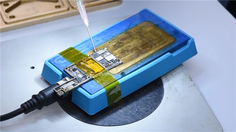
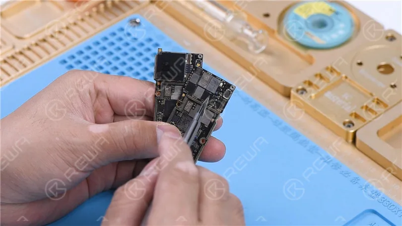
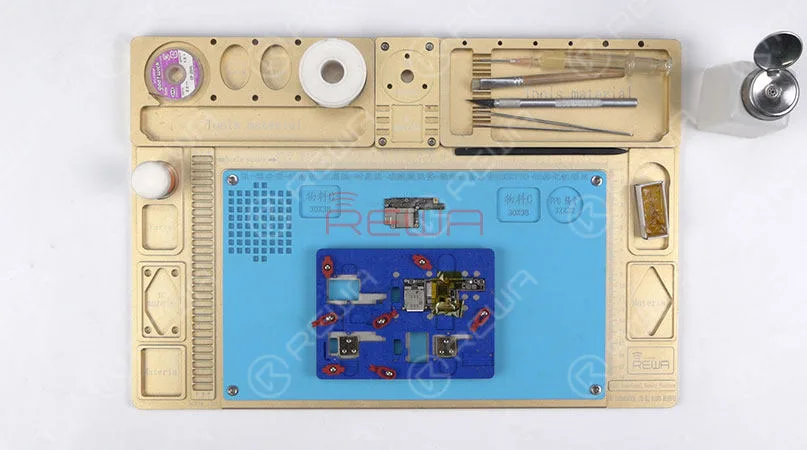
Placer la carte mère sur la plate-forme chauffante spécialisée. Lorsque la température de la plate-forme atteint la température de consigne. Détachez la couche supérieure et la couche inférieure de la plate-forme à l'aide d'une pince à épiler. La couche supérieure et la couche inférieure de la plate-forme sont détachées à l'aide d'une pince. Plate-forme de chauffage spécialisée est parfait pour la séparation de la carte mère de l'iPhone X.
Étape 2 : Recherche de défauts
Si l'on examine les deux couches au microscope, on constate que la couche supérieure ne présente aucun problème. En revanche, certaines zones de la couche inférieure présentent des signes évidents de dommages causés par l'eau. Nettoyons d'abord la carte mère.
Étape 3 : Analyse des défaillances
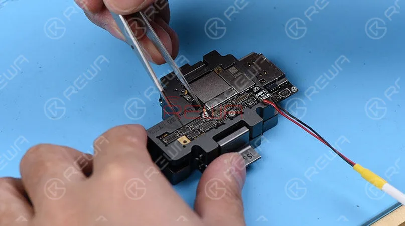
Attachez la couche supérieure et la couche inférieure au dispositif de test et mettre le téléphone sous tension à l'aide d'une pince à épiler. La lecture du courant sur l'ampèremètre passe à 100mA puis reste immobile, ce qui est anormal. Branchez le connecteur de la batterie sur la couche supérieure et mettez le téléphone sous tension. La lecture du courant sur l'ampèremètre est normale. À en juger par ces résultats, la couche supérieure n'a rien à voir avec le problème de mise sous tension et le défaut est probablement lié à la couche inférieure. La prochaine étape consiste donc à mesurer davantage la couche inférieure.
Étape 4 : Confirmation des défauts
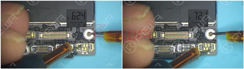
Effectuez une mesure en mode diode des condensateurs autour de l'IC U3400 moisi, et il n'y a pas de problème de court-circuit autour de l'U3400. Poursuivez la mesure en mode diode de la carte de circuit imprimé du troisième espace. La valeur mesurée de la broche S30 est de 40, ce qui est anormal. Comme la broche S30 est connectée directement à la broche L4 de l'U3400, le défaut est probablement lié à l'U3400. La prochaine chose à faire est donc de vérifier l'U3400. Tout d'abord, retirez l'U3400 à l'aide d'un pistolet à air chaud. Nous pouvons voir que l'U3400 et son tampon de collage ont fortement moisi. Il faut donc le remplacer par un nouveau circuit intégré.
Étape 5 : Élimination des défauts
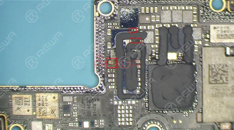
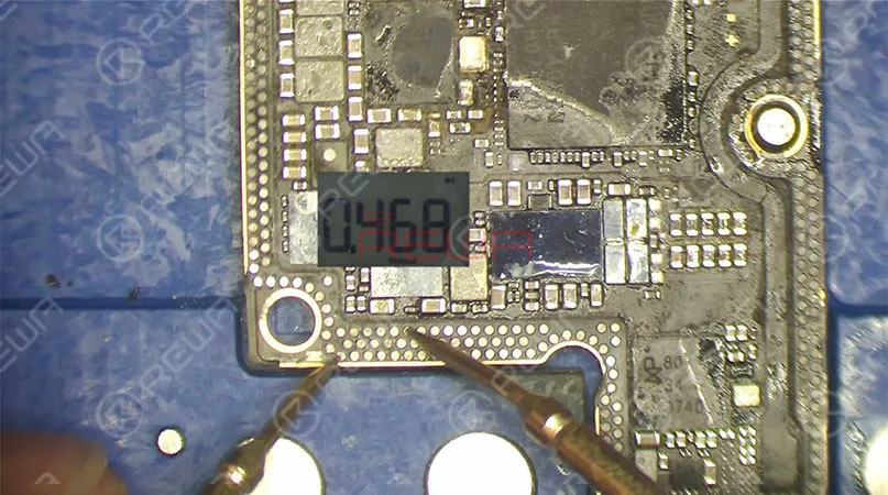
En nettoyant le bonding pad, nous constatons que trois composants autour de U3400 ont été soumis à différents degrés de corrosion. Nous devons retirer les trois composants un par un et souder de nouveaux composants aux positions correspondantes. Après cela, nous pouvons passer à la soudure des circuits intégrés. Une fois cela fait, attendez que la couche inférieure refroidisse pendant 5 minutes. Effectuez à nouveau une mesure en mode diode de la broche S30 sur le troisième espace du circuit imprimé. La valeur mesurée est de 468, ce qui est normal.
Étape 6 : Test
Fixez maintenant la couche supérieure et la couche inférieure au dispositif de test. La lecture du courant sur l'ampèremètre est normale cette fois-ci et le téléphone s'allume normalement.
Étape 7 : Reballage
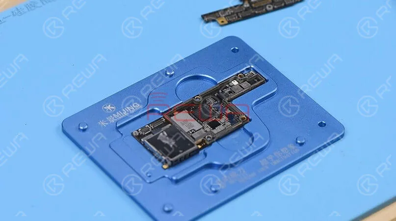
Dans cette étape, nous utiliserons un outil très utile, connu sous le nom de Moule spécialisé pour le reballage de l'iPhone X. Il peut nous aider à mener à bien le processus de reballage.
Étape 8 : Recombinaison de la carte mère
Grâce à la plateforme chauffante spécialisée de l'iPhone X, le processus de recombinaison de la carte mère est très facile et efficace. Attendez que la carte mère refroidisse pendant 10 minutes.
Étape 9 : Assembler et tester
Nous pouvons maintenant assembler le téléphone et le tester. Appuyez sur le bouton d'alimentation pour allumer le téléphone. Le téléphone s'allume normalement. Le problème est résolu. Conseils chaleureux : faire assembler le téléphone après confirmation de l'élimination du défaut. iPhone X ne s'allume pas à cause d'un dommage causé par l'eau réparé parfaitement.
Pour plus de détails sur le dépannage de l'iPhone X endommagé par l'eau, rendez-vous ici : BOUTIQUE EN LIGNE REWA EST OUVERT, ÉQUIPÉ DE TOUS LES OUTILS UTILISÉS DANS LE BLOG, PRÊT À FAIRE FONCTIONNER VOTRE ENTREPRISE DE RÉPARATION ?
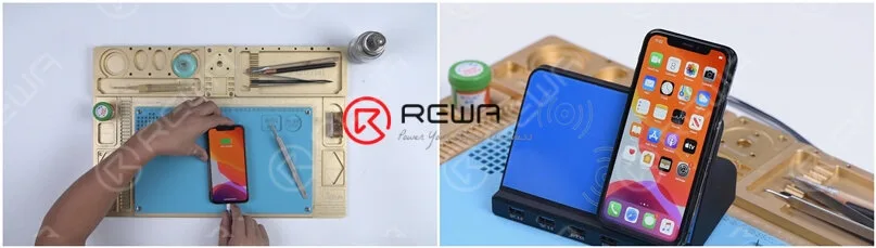
Wireless charging technology has been prevalent in today’s smartphones. Wireless charging appears so convenient and effortless that more and more people are eager to try it and use it in their daily life. However, the reality is not always as smooth as expected. You place the iPhone on the charging pad, but nothing happens. In this article, we will share how to fix an iPhone X that is not wirelessly charging.
1. Motherboard Check
First of all, run a cosmetic inspection of the motherboard. The motherboard is not deformed or water-damaged.
2. Assemble and Test
In the next place, assemble the phone and test. Press the power button to turn on the phone. The phone turns on normally.
Plug in the charging cable. The phone can be charged with the charging cable. Place the phone on a wireless charger. The phone cannot be wirelessly charged.
We need to focus on wireless charging relevant circuits.
3. Run Diode Mode Measurement of the Wireless Charging Connector
Take apart the phone and take out the motherboard. Remove the dust-proof sponge covering the board first. Then run diode mode measurement of the wireless charging connector. The measured value is normal, which indicates that wireless charging relevant circuits on the bonding pad are normal. We need to move on to wireless charging relevant circuits on the lower layer.
4. Motherboard Separation
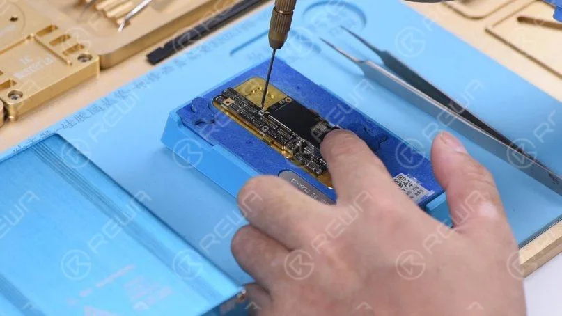
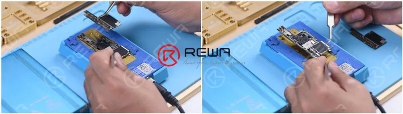
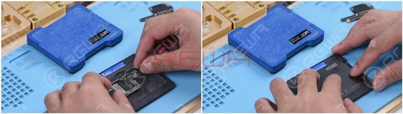
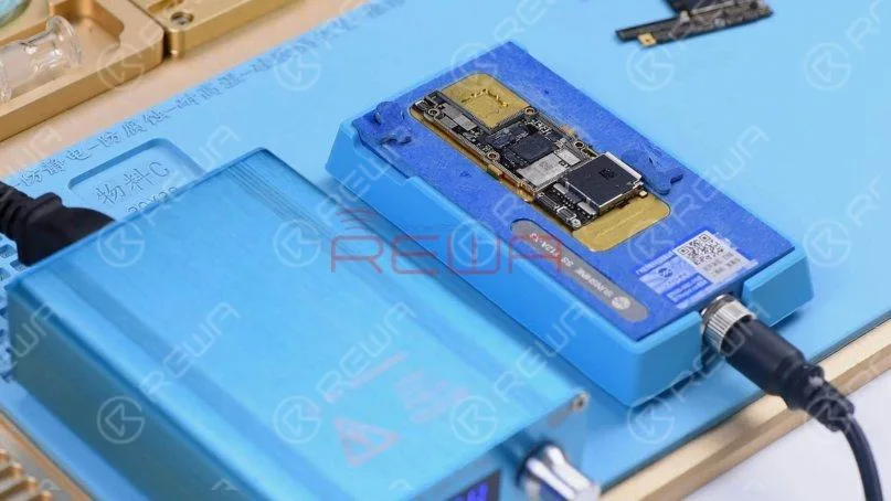
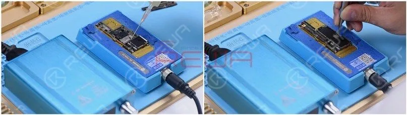
The first thing we do is to separate the upper layer from the lower layer. Place the motherboard on the plate-forme de chauffage and fit a screw into the screw hole on the motherboard. So we can take down the upper layer efficiently afterward.
Heat the motherboard for 2 minutes on the heating platform at 165℃. After heating, take down the upper layer with tweezers and then the lower layer.
5. Lower Layer Inspection
Run a cosmetic inspection of the lower layer. Nothing goes wrong. Run diode mode measurement of capacitors around the wireless charging IC. Judging by the measured value, there is no short-circuited condition. Continue measuring diodes around the wireless charging IC. The measured value is also normal.
6. Wireless Charging IC Replacement
Let’s try to replace with a new wireless charging IC and see how it works.Attach the lower layer to the PCB holder and apply some paste flux to the wireless charging IC. Heat with QUICK 990 AD Hot Air Gun at 360℃, air flow 3 for about 1 minute. Take down the wireless charging IC from the board with tweezers.
Continue to apply some pâte à souder à température moyenne to the bonding pad. Heat with fer à souder at 365℃ to clean the bonding pad. Once done, heat with Hot Air Gun at 360℃, air flow 3 to clean the bonding pad with rosin soaked mèche à souder.
Clean with PCB cleaner afterward and apply some paste flux to the bonding pad.
Get a new wireless charging IC in the right position and solder with QUICK 990 AD Hot Air Gun at 360℃, air flow 3.
7. Motherboard Restoration
The next thing we need to do is to solder the two layers together. Clean the bonding pad before soldering. Once done, get the bonding pad reballed.
Once completed, place the lower layer on the heating platform. Apply some BGA paste flux to the bonding pad and get the upper layer in the right position. Heat for 2 minutes on the heating platform at 165℃.
Nous pouvons maintenant assembler le téléphone et le tester.
8. Wireless Charging Not Working On iPhone X Has Been Successfully Fixed
Get the motherboard installed and display assembly connected. Press the power button to turn on the phone. The phone turns on normally.Place the phone on a wireless charger and the phone can be wirelessly charged.
Conclusion :
iPhone X wireless charging is not working. Plug in the charging cable and test. The phone can be charged with the charging cable. So we need to focus on wireless charging relevant circuits. Check wireless charging relevant components around the wireless charging IC. All going well. Try to replace with a new wireless charging IC and the problem is fixed.If you are looking for more in-depth content and want to study systematically, please feel free to visit Académie REWA.
Our repair case today is about repairing an iPhone X that won’t charge but with the lightning bolt showing up.
First of all, let’s get the motherboard installed and test. The phone turns on normally. Plug the charging cable and the lightning bolt shows up. However, there is no charging current on the ammeter. Judging by this, the motherboard can detect the power adapter whereas the phone won’t charge.
Since the housing, the battery, and the charging port flex cable used for the test are known-good parts, we need to focus on the charging circuit on the motherboard. The first thing we need to do is to separate the upper layer from the lower layer. Place the motherboard on the heating platform and fit a screw into the screw hole on the motherboard. So we can take down the upper layer efficiently afterward. Heat the motherboard for 2 minutes on the heating platform at 165℃.
Remove the upper layer and lower layer with tweezers.
Run diode mode measurement of Pin 2 and Pin 3 on the battery connector J3200. The measured value is normal.
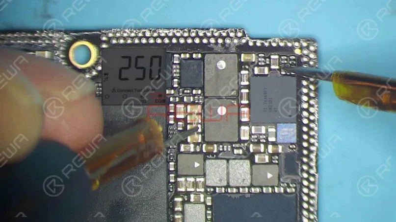
Continue measuring TIGRIS_LX between charging IC U3300 and Q3350. The measured value is 250, which is abnormal. The normal value should be 0. Judging by the measured value, TIGRIS_LX has open-circuited.
L3341 and L3340 are connected in series on the circuit. The open-circuited condition indicates that the two inductors might have been pseudo soldered or damaged. We need to replace the two damaged inductors with new inductors. Attach the upper layer to the PCB holder and stick high-temperature tape on components around. Heat with QUICK 990AD Hot Air Gun at 300℃ and airflow 3. Remove black adhesive around the two inductors.
Once done, apply some paste flux to the two inductors. Heat with Quick 990AD Hot Air Gun at 360℃ and airflow 3.
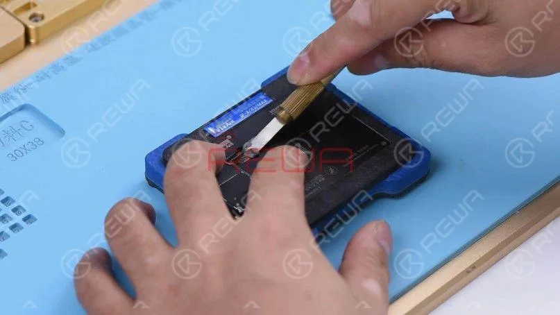
Pry up the two inductors carefully with the pry knife.
Continue to apply some medium-temp solder paste to the two bonding pads. Tin the two bonding pads with Soldering Iron at 365℃. Then clean black adhesive on the bonding pad.
Continue to apply some paste flux to the two bonding pads. Get the two inductors in the right position, and solder with QUICK 990AD Hot Air Gun at 360℃ and airflow 3.
Clean with PCB cleaner afterward. Again, let’s run diode mode measurement of TIGRIS_LX between U3300 and Q3350. The measured value is 0, which is normal.
Now we need to attach the upper layer and the lower layer to the testing fixture and test. Firstly, clean the bonding pad.
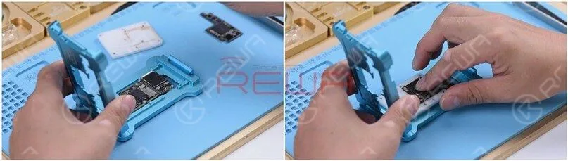
Then attach the upper layer and the lower layer to the testing fixture.
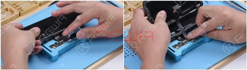
Get the charging port flex cable connected. Then get the screen and the battery connected.
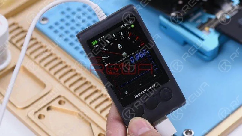
Plug the charging cable. The charging current on the ammeter is 860mA, which indicates that the phone can be normally charged.
The next thing we need to do is to solder the two layers together. We need to get the lower layer reballed first. Put the lower layer into the reballing moldand get the BGA Reballing Stencil in position.
Place the mold onto the base. The stencil is tightly attached to the lower layer because of the magnetic structure of the base. Then we smear some low-temp solder paste on the stencil and wipe off excess solder paste with a lint-free wipe.
After reballing, take the mold down from the base and remove the reballing stencil. Heat the lower layer on the heating platform at 165℃. Once solder balls have shaped up completely, power off the heating platform.
Cool for 5 minutes. Apply some BGA Paste Flux to the bonding pad and get the upper layer in position. Then power on the heating platform. With the temperature reaching 165℃, continue heating for 2 minutes.
Turn the power off and cool for 5 minutes. Then take down the motherboard from the heating platform. Please check carefully to make sure that the two layers have been soldered together perfectly. Now we can assemble the phone and test. Get the motherboard installed and display assembly connected. Plug the charging cable. The lightning bolt shows up on the screen. The charging current on the ammeter is also normal. The fault is cleared.
Conclusion :
The lightning bolt shows up on the iPhone X screen while there is no charging current on the ammeter. Check the charging circuit on the motherboard and one rail has open-circuited. Replace the two inductors on the rail and the problem is fixed.
If you are looking for more in-depth content and want to study systematically, please feel free to visit our académie.
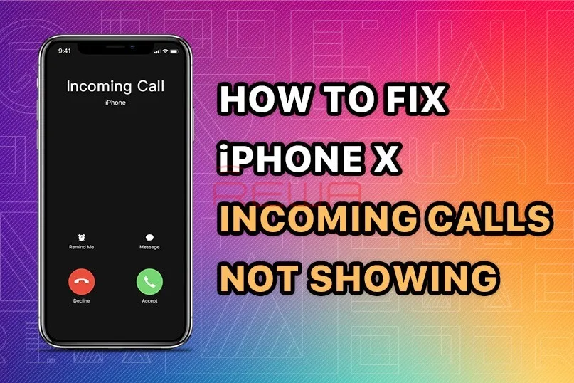
Some iPhone users may encounter such a problem, when the phone screen is turned off, we cannot receive the call.
Right now, there are few solutions to fix iPhone not responding in sleep mode when getting incoming calls.
The general repair process of a repair technician is to take out the motherboard, check PMU and baseband CPU, and then replace or re-solder the faulty component.
The whole repair process is complicated and difficult.
Now REWA LAB will show you a brand new ‘signal borrowing’ solution to fix this problem quickly and efficiently.
Problème
Here we have an iPhone X not responding in sleep mode when getting incoming calls. When we were trying to test the Sounds&Haptics function, we found all going well.
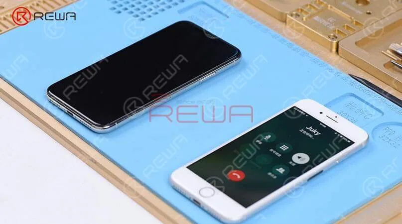
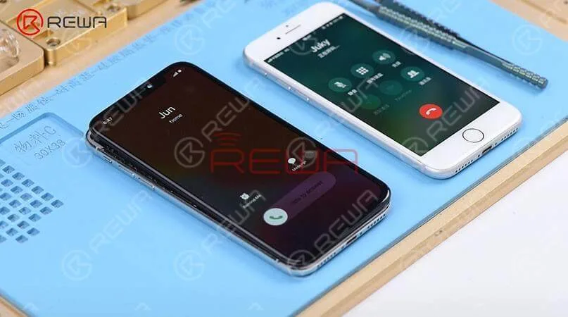
With the screen on, we placed a call to the phone using a known-good phone. And the decline and answer buttons appear on the screen.
However, if we turned the screen off, the phone is not responding at all. Then we pressed the power button to turn the screen on and we can see the incoming calls showing on display.
Diagnostic
Judging by this, we can infer that relevant circuits of the baseband wake signal might have malfunctioned. So we took apart the phone, disconnected the battery, removed the display assembly, and took out the motherboard.
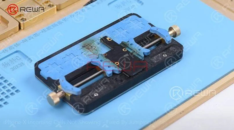
The following step is to attach the motherboard to the PCB Holder and then heat with Hot Air Gun at 200℃, airflow 3 to tear off the heat dissipation sticker on the backside of the motherboard.
Confirm the Signal Fault Location
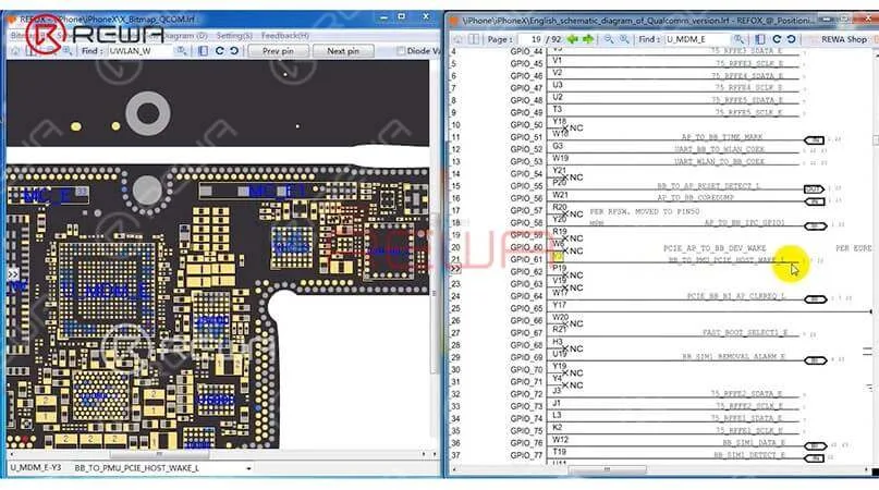
We can open the bitmap software in Refox and locate BB_TO_PMU_PCIE_HOST_WAKE_L first.
Since relevant circuits of the wake signal might have malfunctioned, so we can try to borrow the wake signal from WiFi relevant circuits.
Borrow Signal by Jumping a wire
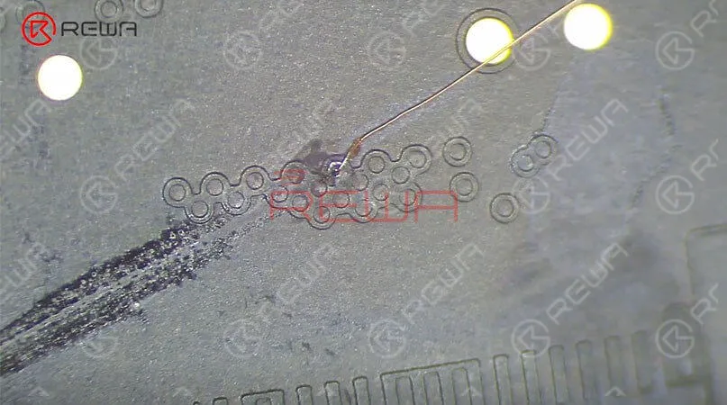
Then we need to locate WLAN_TO_PMU_HOST_WAKE. And the following step is to connect PP101_E-1 (the test point of the baseband wake signal) with PP7611_W-1 (the test point of the WiFi wake signal) by jumping a wire.
Before that, we need to scrape off the insulating coating on the two test points first, then apply some solder paste to the two bonding pads and heat with Soldering Iron at 365℃.
The next step is to tin the two bonding pads with solder paste and also to connect PP101_E-1 to PP7611_W-1 with 0.02mm Enameled Copper Wire.
Finally we need to coat the wire with the UV Curable Solder Mask.
Assemble the Phone and Test
Now we can assemble the phone and test. We got the motherboard installed and displayed assembly connected, then connected the battery.
Then pressed the power button to turn on the phone inserted the SIM card. After that, with the screen off, we tested again. And we found all going well.
PS: The repair case of this blog is applicable to the QCOM version, which might be a reference for the Intel version as a repair method.
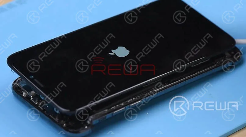
iPhone gets stuck on the Apple logo, which usually means that there is a problem with the operating system or hardware of the phone.
Today, we will show you a rare case of iPhone X stuck on apple logo, and teach you how to diagnose and fix the problem step by step.
Inspection cosmétique
As we always do, we should run a cosmetic inspection of the motherboard first.
Check out the condition of the motherboard, whether it is deformed or water damaged.
Then get the motherboard installed, the phone enters into recovery mode automatically.
Judging by this, the motherboard comes with restore failure. Therefore, the phone cannot enter into the system normally.
Diagnostic
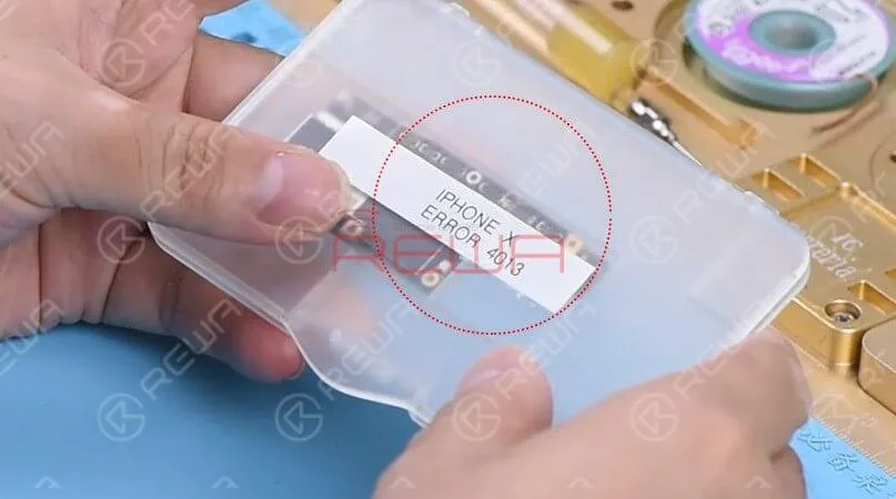
Let’s restore the phone with 3U Tools and check whether it comes with error 4013.
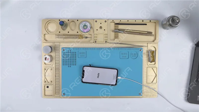
The phone can be normally activated after restore.
Next, check baseband info in the settings. If it shows normal, we can confirm now that the motherboard is normal. The fault is probably related to other parts.
Get the earpiece speaker and sensor flex cable and front camera flex cable installed.
Turn on the phone, the phone is stuck on the Apple logo and keeps restarting.
Judging by this, the fault is related to the earpiece speaker and sensor flex cable or the front camera flex cable.
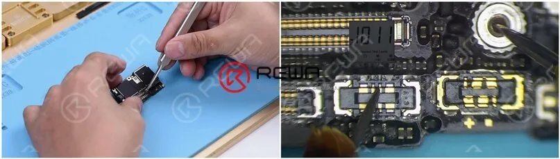
Check the earpiece speaker and sensor flex cable carefully, we find that the Flood illuminator module is moldy.
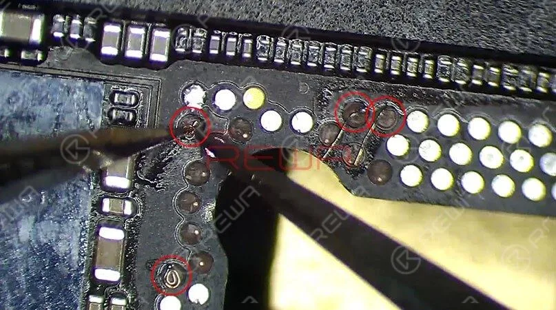
Remove the Flood illuminator module, we can see that its bonding pad is severely corroded.
That’s what’s causing the problem.
Maintenance
The next section will explain the detailed repair steps:
Apply some paste flux to the bonding pad.
Clean the bonding pad with Soldering Iron.
Apply solder paste to the severely corroded pad.
Nettoyer ensuite avec le PCB Cleaner.
Apply some paste flux to the bonding pad.
Get the Flood illuminator module in the right position.
Solder it with Hot Air Gun.
Test
Get the earpiece speaker and sensor flex cable installed, then assemble the phone.
The phone turns on normally. Since the two flex cables were not connected during the previous restore, we need to restore again with the two connected.
Restore the phone with the help of 3U Tools.
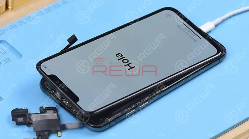
Once completed, the phone enters the system normally, and Face ID works normally.
Le processus de réparation exige non seulement des connaissances théoriques professionnelles, mais aussi des compétences manuelles habiles.
Fixez une couche inférieure connue comme étant bonne au banc d'essai, puis fixez la couche supérieure.
Connectez l'ensemble écran.
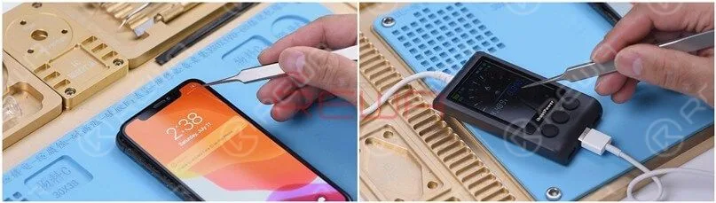
En effectuant le test, nous constatons que le téléphone s'allume normalement et que la fonction tactile est également normale.
À en juger par ceci, le problème tactile est causé par la couche inférieure.
Échange de planches
Puisque la couche inférieure est fortement déformée, nous devons transférer le processeur de bande de base, l'EEPROM de bande de base et la puce NFC de la couche inférieure d'origine vers une nouvelle couche inférieure.
Pour plus de détails, veuillez regarder la vidéo ci-dessous :
Après le remplacement de la carte, nous devons relancer le test en utilisant le banc de test.
Connectez le connecteur de la batterie à l'alimentation CC.
Ensuite, allumez la carte mère à l'aide d'une pince à épiler.
Ici, nous pouvons trouver le numéro de série IMEI et le micrologiciel du modem, ce qui indique que l'échange de la couche inférieure a été effectué avec succès.
Recombinaison de la carte mère
La prochaine étape consiste à braser les deux couches ensemble.
Voici les étapes suivantes :
Fixez la nouvelle couche inférieure au moule de reballing spécialisé.
Recouvrez la nouvelle couche inférieure avec le pochoir de reballage correspondant.
Étalez un peu de pâte à braser basse température sur le pochoir.
Retirez délicatement le pochoir de reballing.
Continuez à placer la nouvelle couche inférieure sur la plateforme chauffante.
En attendant la fusion de la pâte à braser, les billes de soudure commencent à se former.
En attente du refroidissement de la couche inférieure pendant 10 minutes.
Appliquez le flux de pâte BGA sur le circuit imprimé du troisième emplacement, mettez la couche supérieure en position.
Chauffer pendant 1 minute sur la plaque chauffante à 160 degrés.
Avec la couche supérieure qui s'affaisse et le flux en pâte qui s'écoule, les deux couches ont été soudées ensemble avec succès.
Attendez 5 minutes que la carte mère double étage refroidisse.
Restauration de True Tone
Une fois que nous aurons fini de réparer la carte mère, il sera temps de transplanter les pièces.
REWA possède des années d'expérience dans la fourniture de services de gros pour une vaste gamme de produits électroniques couvrant les pièces détachées de téléphones portables et les batteries de remplacement.
Nous adhérons au principe de ” La qualité avant tout ” tout au long des processus de fabrication et de test. Voici certains de nos produits sélectionnés :
Ensuite, nous allons réparer le True Tone du nouvel écran.
Connectez l'écran d'origine avec le module d'extension d'affichage, lisez les données de l'écran d'origine avec le Programmateur de réparation True Tone.
Une fois terminé, connectez le nouvel écran au module d'extension d'affichage.
Écrire les données stockées de l'écran d'origine sur le nouvel écran.
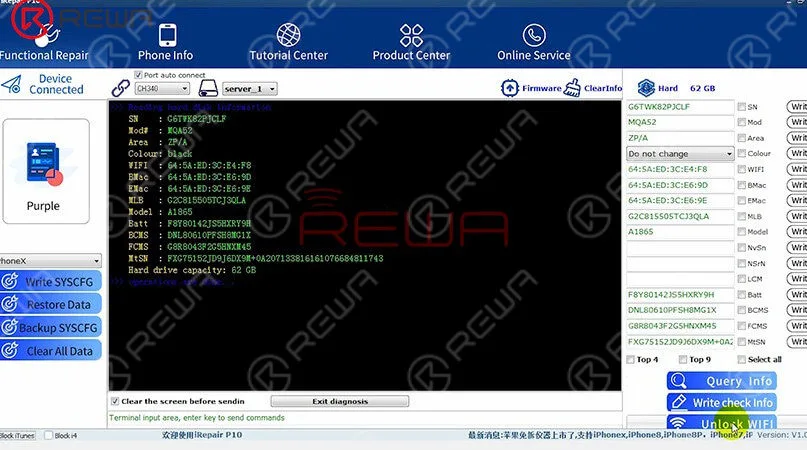
Dissociation du Wi-Fi
Comme nous n'avons pas traité le circuit intégré Wi-Fi sur la carte mère, l'interrupteur Wi-Fi ne peut pas être activé.
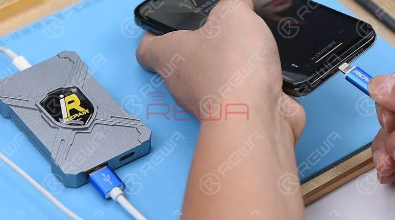
Voici un outil que nous recommandons qui s'appelle iRepair DFU Box.
Connectez-le à l'ordinateur, puis connectez le téléphone au boîtier.
Mettez le téléphone en mode DFU, puis exécutez le logiciel.
Une fois terminé, l'interrupteur WiFi redevient normal.
L'iPhone X a été restauré avec succès après notre dur travail.
Réparer un téléphone portable, c'est tout comme pratiquer une intervention chirurgicale sur un téléphone.
Vous devez analyser le problème puis le résoudre étape par étape.
Le processus de réparation exige non seulement des connaissances théoriques professionnelles, mais aussi des compétences manuelles habiles.
Commencez votre parcours d'apprentissage avec REWA ACADEMY dès maintenant ! Aperçu de ce cours :Cours de réparation des cartes logiques de l'iPhone
We've detected you might be speaking a different language. Do you want to change to:






 English
 Español
 Français
 Deutsch
 Italiano