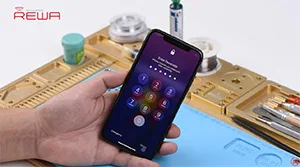
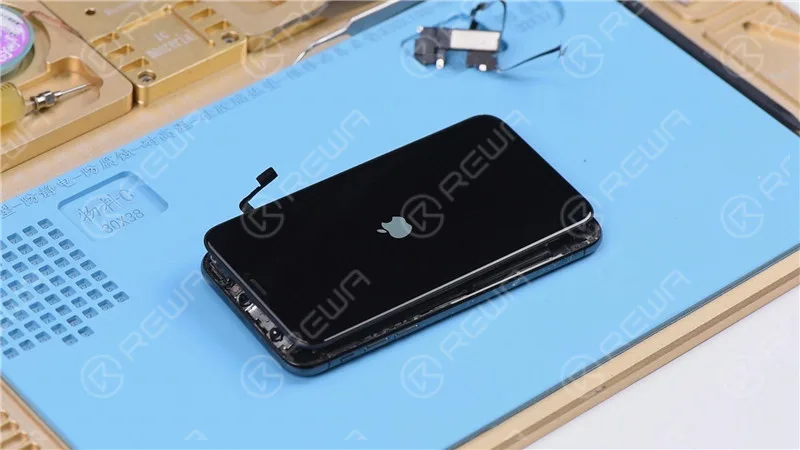
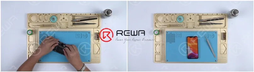
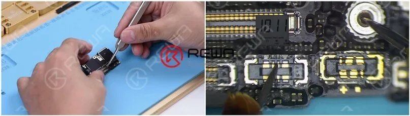
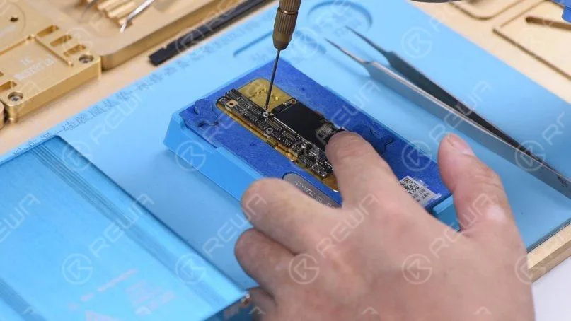
Face ID lets you securely unlock your iPhone, authenticate purchases and sign in to apps all with just a glance. However, due to the vulnerability of the Face ID parts, it can be easily damaged when iPhone X is dropped or during screen replacement, which will result in Face ID failure. Don’t worry. In this video, REWA guides you to fix “Face ID Is Not Available” step by step. Let’s check.
This is also a reminder. Please be careful in your daily use of the phone!
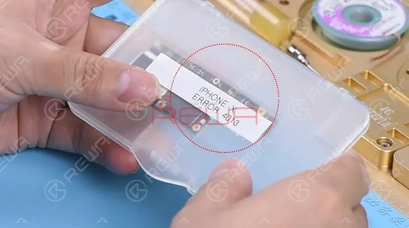
Puede ser extremadamente frustrante encontrar su iPhone atascado en el logotipo de Apple o iTunes Error 4013. En la mayoría de los casos, esto no es un problema grave y una actualización de software puede resolver el problema. Sin embargo, si la actualización de software no resuelve el problema, puede ser un problema de hardware que requiere un diagnóstico más profundo y la reparación.
Error 4013 del iPhone: Posibles causas
El Error 4013 del iPhone puede producirse debido a varios factores, que abarcan tanto componentes de software como de hardware, que contribuyen a la aparición de este desconcertante error.
Versión obsoleta de iTunes
Una de las principales causas del error 4013 del iPhone es una versión obsoleta de iTunes. Dado que iTunes es crucial tanto para restaurar como para actualizar el dispositivo, es imprescindible mantenerlo al día. Una actualización de software sencilla y gratuita puede resolver a menudo este problema, garantizando una comunicación fluida entre el iPhone y el ordenador.
Fallos de software
Los fallos aleatorios del firmware a veces pueden provocar el Error 4013 del iPhone. Realizar un reinicio forzado o hard reset puede ayudar a superar estos fallos de software. Manteniendo pulsados los botones apropiados, puedes iniciar un reinicio que puede rectificar el error y restaurar la funcionalidad normal.
Complicaciones de hardware
Aunque los problemas de software son culpables comunes, los problemas de hardware también pueden desencadenar el Error 4013 del iPhone. En algunos casos, el sudor u otras formas de líquido que entran en el auricular pueden causar un bucle de arranque y provocar este error. Además, los cables USB defectuosos, los puertos USB dañados o el software de seguridad de terceros pueden contribuir a este frustrante problema.
Esta entrada del blog abordará exclusivamente los problemas de hardware que pueden provocar este problema.
Nota: Tenga en cuenta que este tutorial utiliza un iPhone X para fines de demostración, aunque el método se puede aplicar a la mayoría de los modelos de iPhone.
Inspección cosmética de la placa base
Antes de lanzarse a la resolución de problemas, es esencial asegurarse de que la placa base está en condiciones óptimas. Comprueba si hay deformaciones o daños por agua que puedan dificultar el proceso de reparación.
Identificar el problema
Vamos a proceder con la instalación de la placa base y probarlo pulsando el botón de encendido. Sin embargo, el teléfono entra automáticamente en modo de recuperación, lo que indica un posible fallo de restauración con la placa base. Como resultado, el teléfono es incapaz de arrancar en el sistema normalmente.
Restaurar el teléfono
Para empezar, conecta tu iPhone X a un ordenador e inicia el proceso de restauración con 3U Tools. Una restauración satisfactoria indica que la placa base funciona correctamente y que tu teléfono puede activarse con normalidad.
Diagnóstico de otros problemas
Restauración con éxito
Si el teléfono puede restaurarse con éxito y activarse, es un indicio de que la placa base funciona correctamente. Es probable que el problema se encuentre en otra parte.
Comprobación de la información de banda base
Vaya a Configuración>General>Acerca de para verificar la información de banda base, reforzando la salud de la placa base.
Localizar el problema
Añadir cables flexibles: Para reducir el problema, vuelve a conectar el altavoz del auricular y el cable flexible del sensor junto con el cable flexible de la cámara frontal, e intenta encender el teléfono.
Atascado en el logotipo de Apple: Si el teléfono se queda atascado en el logotipo de Apple y se reinicia, sugiere un problema con el altavoz del auricular y el cable flexible del sensor o el cable flexible de la cámara frontal.
Aislar el problema
Desconexión del altavoz del auricular y del cable flexible del sensor: Retire el altavoz del auricular y el cable flexible del sensor y, a continuación, intente encender el teléfono. Si se enciende normalmente, el problema está relacionado con estos componentes.
Fijación del módulo iluminador de inundación
Examen microscópico: Inspeccione el módulo del iluminador de inundación e identifique cualquier moho o corrosión.
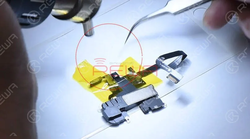
Reparación con cinta de alta temperatura: Fije el altavoz del auricular y el cable flexible del sensor con cinta adhesiva de alta temperatura. Caliente la zona afectada con una pistola de aire caliente a 320℃ con un caudal de aire de 35. Retire el módulo iluminador Flood dañado.
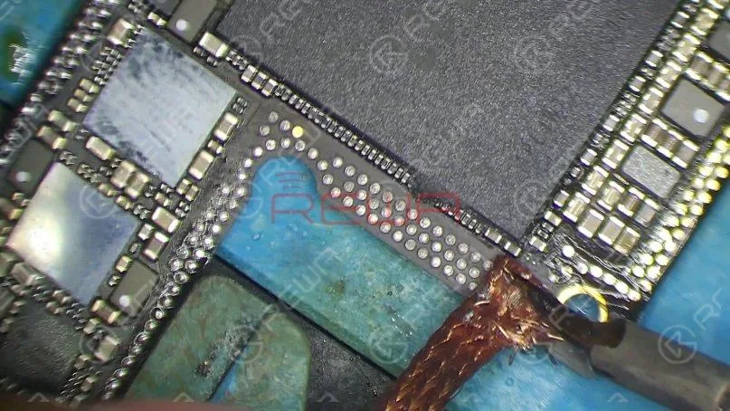
Almohadilla de unión corroída: Si la almohadilla de unión del módulo iluminador de inundación está muy corroída, aplique fundente en pasta, limpie con un soldador a 360℃ y vuelva a aplicar pasta de soldar a temperatura media. A continuación, limpie con PCB Cleaner.
Montaje: Vuelva a montar el módulo iluminador Flood, aplicando fundente en pasta y soldándolo en su lugar con una pistola de aire caliente a 320℃.
Espere 2 minutos: Deje que los componentes reparados se asienten durante dos minutos.
Pruebas y restauración
Reconexión: Vuelva a instalar el altavoz del auricular y el cable flexible del sensor, conecte la batería y encienda el teléfono.
Restauración con componentes conectados: Dado que los cables flexibles no estaban conectados durante la restauración anterior, restaura el iPhone X con ambos cables conectados para garantizar la funcionalidad de Face ID.
Verificación final
Entrando en modo DFU: Coloca el teléfono en modo DFU y conéctalo al ordenador.
Restauración: Utilice 3U Tools o un software similar para restaurar el teléfono. Si se completa con éxito, y el teléfono se inicia en el sistema y permite la configuración de Face ID, el problema se ha resuelto.
Video Guia para Arreglar iphone atascado en el logo de apple
Conclusión:
En esta guía completa, hemos recorrido el proceso de solución de problemas y reparación de un iPhone X atascado en el logotipo de Apple con iTunes Error 4013. Al evaluar metódicamente cada componente, desde la placa base hasta el altavoz del auricular y el cable flexible del sensor, hemos identificado y solucionado con éxito el problema, permitiendo que el teléfono funcione normalmente una vez más. Para un conocimiento más profundo de la reparación, considere visitar Academia REWA.
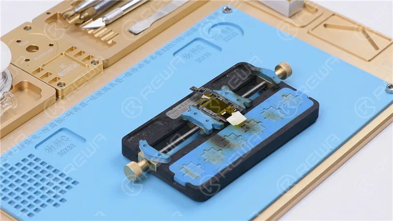
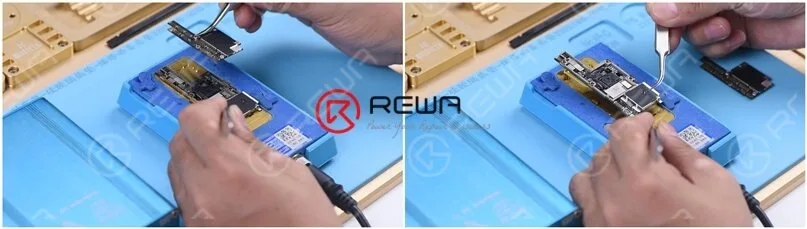
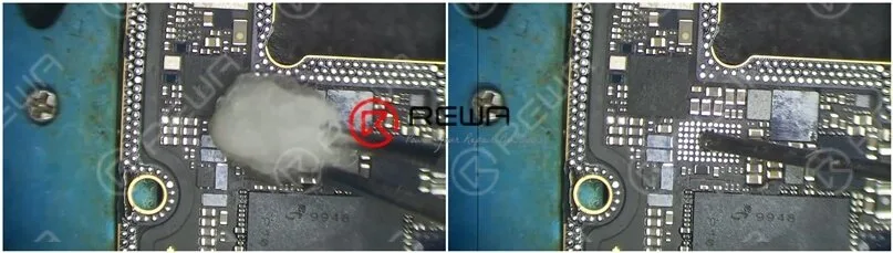
Hola chicos, hoy os guiaremos a través de trucos de reparación para desoldar&soldar el IC de carga del iPhone X.
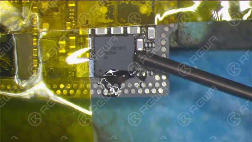
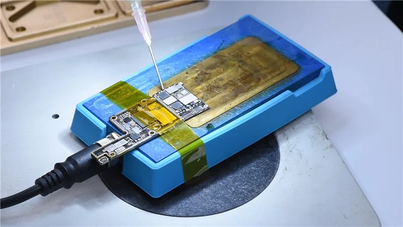
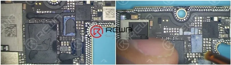
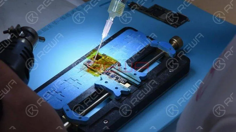
En primer lugar, pegue cinta adhesiva de alta temperatura en los componentes alrededor del CI de carga para protegerlos de la pseudo soldadura/puenteado durante la operación.
A continuación, aplique un poco de fundente en pasta alrededor del circuito integrado de carga.
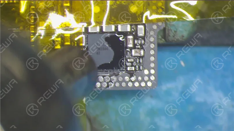
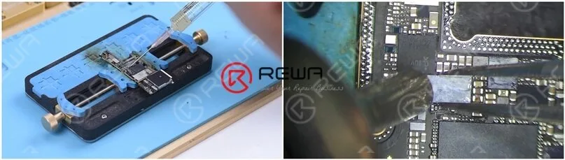
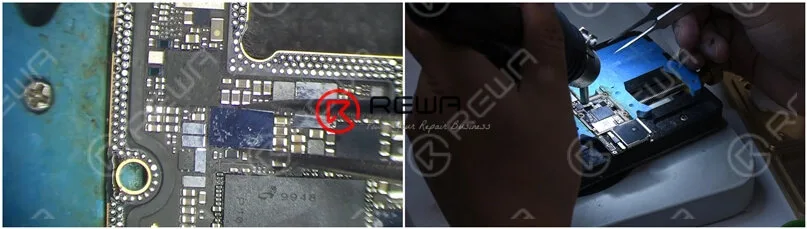
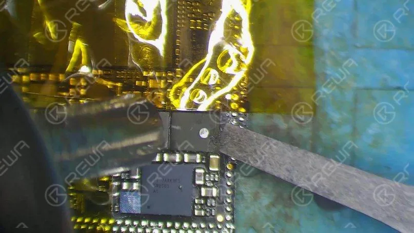
Ajuste la temperatura de la pistola de aire caliente de viento vertical QUICK 990 AD a 330℃, flujo de aire 3. Mantenga la pistola de aire caliente a una altura de 5mm-10mm del CI de carga.
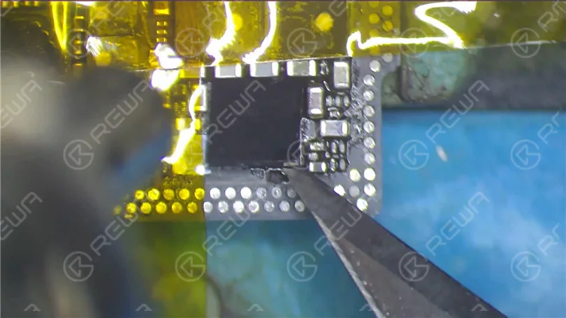
Caliente durante unos 15-20 segundos y, a continuación, levante el circuito integrado de carga. Consejo: controle la fuerza aplicada al levantar el circuito integrado. Las operaciones bruscas podrían dañar el chip o la almohadilla de unión.
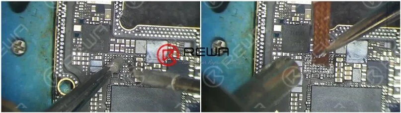
Continúe aplicando un poco de pasta de soldadura de temperatura media en la almohadilla de unión. Calentar con la pistola de aire caliente QUICK 990 AD Vertical Wind a 280℃, flujo de aire 3.
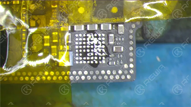
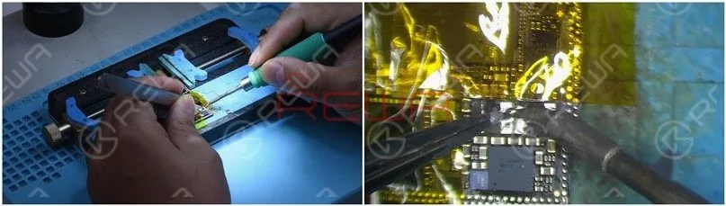
Mientras tanto, limpiar las juntas de soldadura en la almohadilla de unión con soldador en 360℃. Una vez hecho esto, limpie la almohadilla a fondo con una mecha de soldadura empapada en colofonia.
Además, tenga cuidado con su operación aquí. Las operaciones bruscas podrían provocar una pseudo soldadura/puenteado de los componentes alrededor de
Limpiar después con PCB Cleaner.
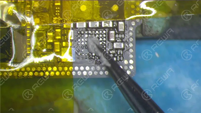
Ahora tenemos que limpiar las juntas de soldadura en la parte posterior del circuito integrado de carga.
Aplique un poco de pasta de soldadura de temperatura media a la almohadilla de unión en la parte posterior. Limpie la almohadilla con el soldador a 360℃.
También puede aplicar un poco de fundente en pasta para una mejor limpieza.
Una vez hecho esto, limpiar con PCB Cleaner. Consejos: no seas demasiado estricto con las juntas de soldadura en el pad. Puede mantener varias juntas de soldadura para un perfecto reballing posterior.
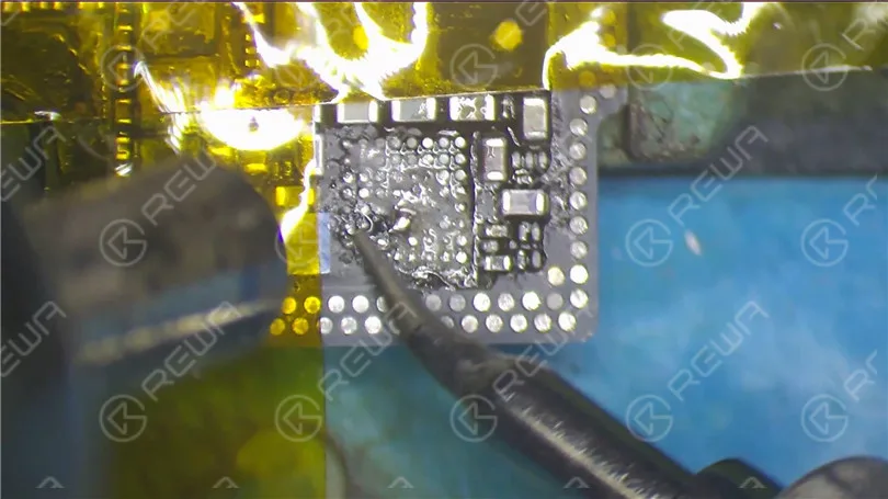
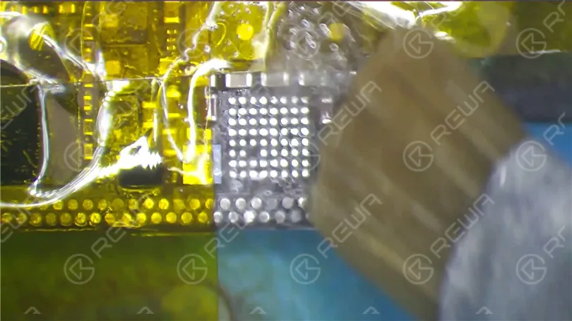
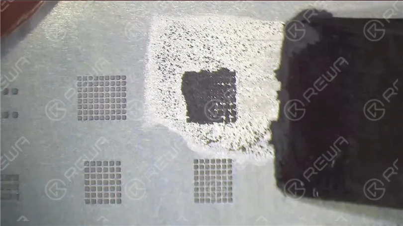
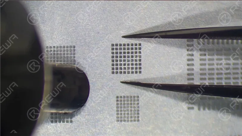
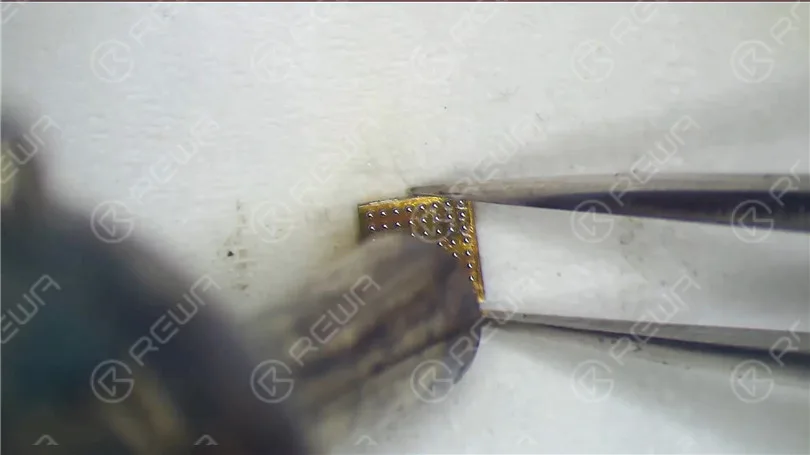
Pasemos al proceso de reballing. Coloca la plantilla BGA en posición. Aplique un poco de pasta de soldadura de temperatura media con el raspador BGA.
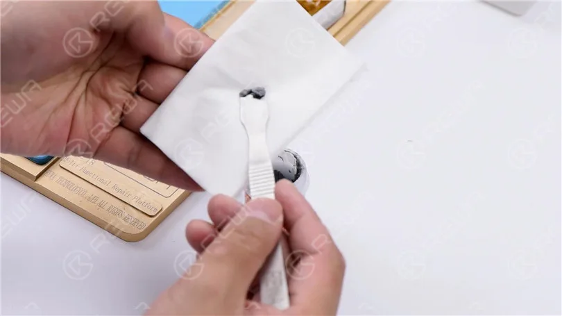
A continuación, aplique la pasta de soldadura a un pañuelo de papel. Esto es para secar la pasta de soldadura envolviendo en el tejido facial.
Para que la pasta de soldadura esté bien preparada para el reballing. Si la pasta de soldar está húmeda, pueden producirse puentes durante el reballing. Continúe untando uniformemente la pasta de soldadura de temperatura media sobre la pantalla. Elimine la pasta de soldadura innecesaria con un paño sin pelusas.
Aplique presión a la BGA Reballing Stencil con unas pinzas. Calentar con la pistola de aire caliente QUICK 990 AD Vertical Wind a 300℃, flujo de aire 3. Para que todas las bolas de soldadura puedan solidificarse completamente.
Consejos: al calentar, la pistola de aire caliente debe acercarse de lejos a cerca, desde los bordes hacia el centro.
El calentamiento concentrado puede deformar la pantalla. El proceso de conformado de las bolas de soldadura también puede verse afectado.
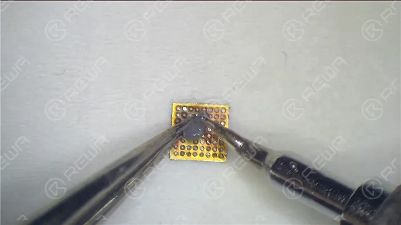
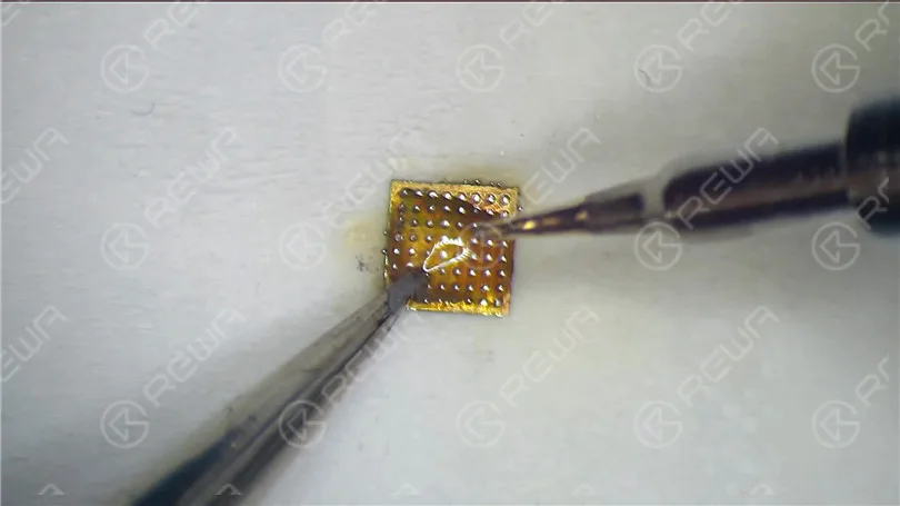
Una vez hecho, enfriar durante 1 minuto. Limpiar después con PCB Cleaner. Separar el chip de la plantilla con unas pinzas suavemente. A continuación, sujete el chip con unas pinzas.
Calentar de nuevo con la pistola de aire caliente QUICK 990 AD Vertical Wind a 300℃, caudal de aire 3. Esto es para asegurar la perfecta formación de las bolas de soldadura.
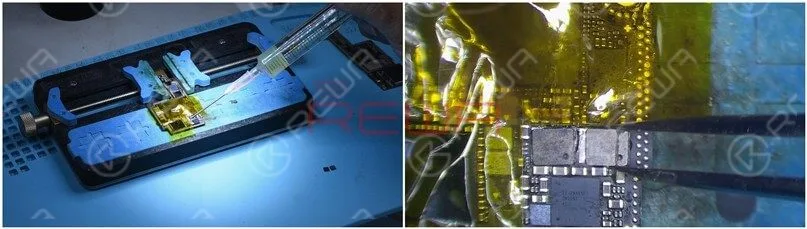
Ahora podemos soldar el circuito integrado de carga. Aplique un poco de fundente en pasta a la almohadilla de unión.
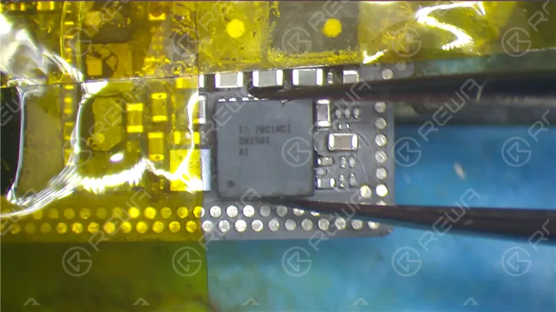
Coloca el circuito integrado de carga en la posición correcta.
No lo coloque en la dirección equivocada. Soldar con la pistola de aire caliente de viento vertical QUICK 990 AD a 330℃, flujo de aire 2. 15s-20s después, con el CI hundiéndose y el fundente de pasta rebosando.
Continuar calentando durante unos 5 segundos. Una vez hecho esto, limpiar con PCB Cleaner.
No dude en visitar Academia REWA para estudiar más técnicas y habilidades de reparación de teléfonos.
iPhone gets stuck on the Apple logo, which usually means that there is a problem with the operating system or hardware of the phone. Check out our video today and we will show you how to diagnose and fix the problem step by step.
Today we will talk about how to replace iPhone X SIM card reader.
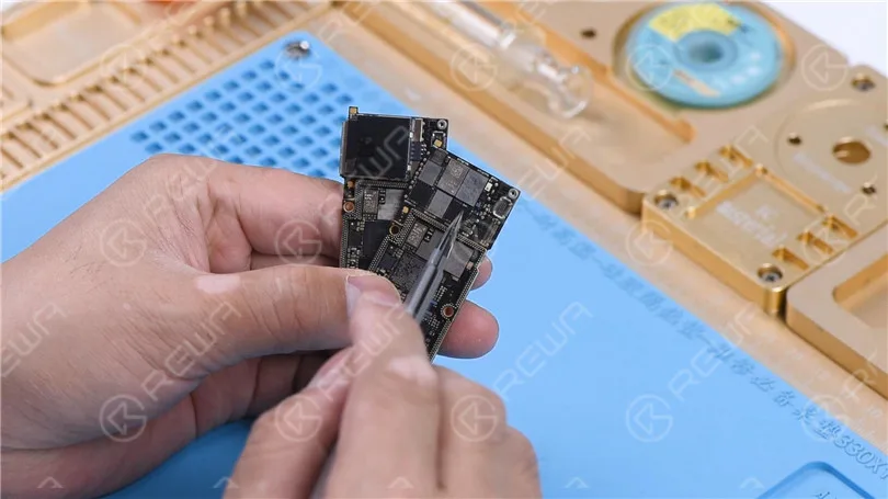
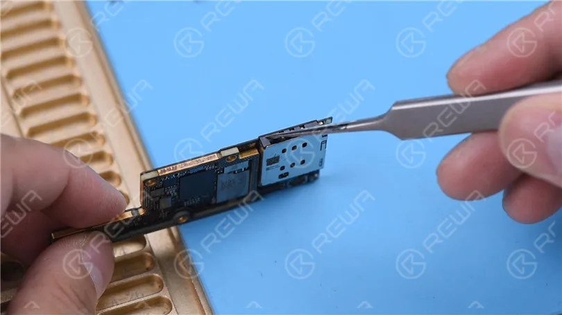
The SIM card reader of iPhone X is soldered with medium-temperature tin, while the middle layer of the motherboard adopts low-temperature tin. Hence we advise you to separate the motherboard before removing the SIM card reader. There are other ICs on the SIM card reader. Besides, a plastic part is also in the middle of the SIM card reader.
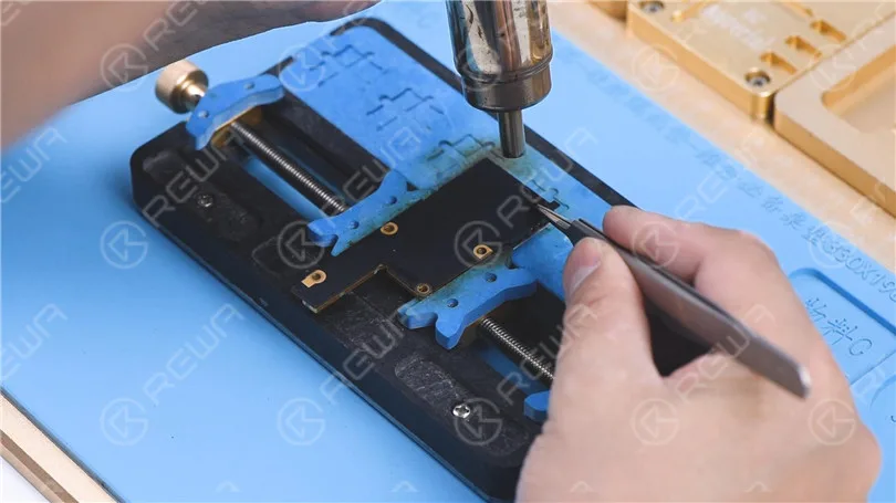
While disassembling and soldering, we need to heat it with rotational air and control the temperature. Attach the motherboard to the PCB Holder. Heat it with Hot Air Gun 240℃ and airflow 7. Tear off the sticker on the back of the motherboard.
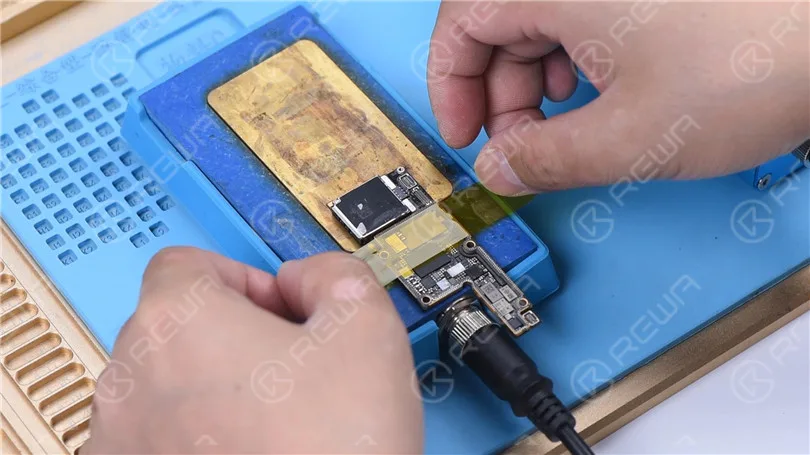
Coloque la placa base en el Plataforma de calefacción. We only need to heat the SIM card reader part. Fix the motherboard with high-temperature adhesive. Set the temperature of the Heating Platform to 200℃. Heat the edge of the SIM card reader with Pistola de aire caliente 280℃ and airflow 7.
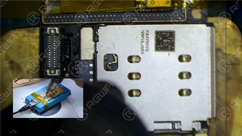
Stir the SIM card reader with tweezers while heating. Remove the SIM card reader when it becomes loose. Please be noted that we need to pick up the SIM card reader in a vertical manner. To avoid damage or malposition of components under the SIM card reader, please do not pry with tweezers. Next, we replace the old SIM card reader with a new one. Apply some Paste Flux to the bonding pad of the SIM card reader. Put the new SIM card reader in position. Keep heating it on the 200℃ Heating Platform. Heat the edge of the SIM card reader evenly with Hot Air Gun 280℃ and airflow 7. Press the SIM card reader gently while heating. Make sure that the SIM card reader is pressing against the PCB.
Turn off the power. Cool the motherboard. Check the SIM card reader soldering. The SIM card reader is pressing against the PCB. Every soldering spot has no pseudo soldering. Solder it again with Soldering Iron if pseudo soldering happens.
Please set the temperature of the Hot Air Gun according to the environment and device brand. The temperature in this article is only for reference.
Visite Academia REWA to study more iPhone repair knowledge.
Frozen o pantalla táctil no responde es uno de los casos más comúnmente vistos en la reparación del iPhone. En general, hay dos causas diferentes para iPhone x pantalla táctil no responde. Mal funcionamiento de los raíles o componentes de la placa base. O el fallo táctil causado por el mal funcionamiento de la pantalla, que se puede arreglar fácilmente sustituyendo por un nuevo conjunto de pantalla.
Hoy te enseñamos a descartar y solucionar el problema empezando por lo simple y luego por lo complejo.
No sabemos dónde está el problema. ¿En la pantalla? ¿O en la placa base? Así que aquí utilizamos una forma sencilla de hacer un juicio preliminar primero. ¡Sustituir con una nueva pantalla sin daños! Si funciona bien en esta placa, podemos confirmar que el problema está relacionado con la pantalla. Como Montaje del digitalizador de la pantalla del iPhone X es caro, no es tan rentable para los clientes cambiar uno nuevo. Así que vamos a intentar arreglarlo. ¡La inspección cosmética va primero!
Podemos ver que el cable flexible táctil no está fracturado, y el conector táctil también parece estar bien. No hay nada extraño en la zona de unión entre el cable flexible táctil y el cable flexible de la pantalla. A juzgar por esto, el fallo probablemente esté causado por el IC táctil o por la propia pantalla. Empecemos por el circuito integrado táctil.
Stick Cinta de alta temperatura alrededor del IC táctil. A continuación, coloque una junta de aislamiento térmico debajo del IC táctil. Caliente con la pistola de aire caliente para eliminar el adhesivo negro alrededor del IC táctil.
Una vez hecho esto, levante el IC táctil. A continuación, limpie la almohadilla adhesiva. Una vez terminado, aplique un poco de fundente en pasta a la almohadilla de unión. Coloca un nuevo circuito integrado táctil y suelda con la pistola de aire caliente. Limpiar con PCB Cleaner después de soldar.
Ahora podemos montar el teléfono y probar si la pantalla táctil del teléfono vuelve a la normalidad. Aquí está el video detallado para su referencia. ADEMÁS: con nuestro sistema de enseñanza único, el curso de formación offline REWA puede ayudar a los técnicos a mejorar sus habilidades de reparación mediante el dominio de los pensamientos y técnicas de reparación. Nuestro curso de formación para abril está en pleno apogeo en Czech ahora mismo. No lo dude más. Inscríbete ahora !
iPhone water damage has always been a frustrating and difficult issue for repair technicians. Things can also be much more difficult when it comes with iPhone X/XS/XS Max. What you usually do with iPhone water damage repair? Got your unique repair thoughts? Well, don’t panic! Our iPhone X water damage repair blog today shall definitely enlighten you.
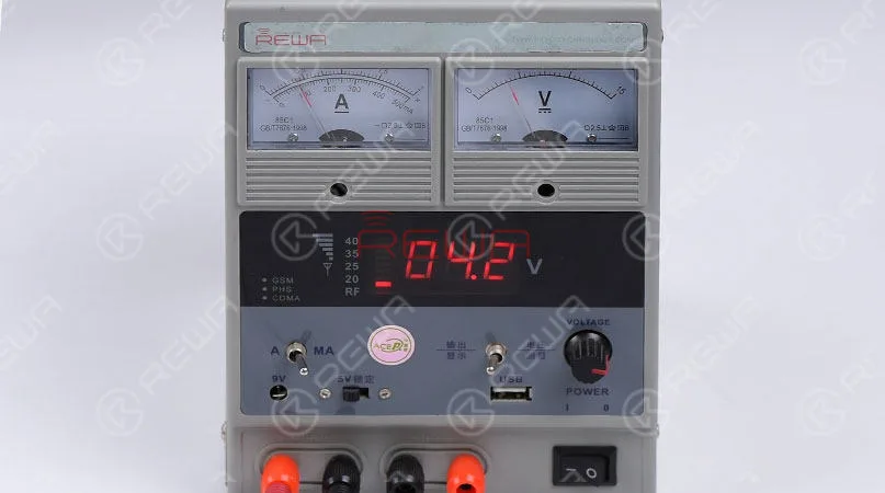
Press the power button to turn on the phone but there is no response at all. Let’s take apart the phone and remove the display assembly first. Connect the battery connector with the DC Power Supply. Current reading on the ammeter jumps to 100mA and then stays still, which is abnormal.
Paso 1: Separación de la placa base
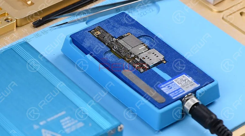
Place the motherboard on the specialized Heating Platform. With temperature of the platform reaching the set temperature. Detach the upper layer and the lower layer from the platform with tweezers. The Plataforma de calefacción especializada is perfect for iPhone X motherboard separating.
Step 2: Fault Finding
Check the two layers under the Microscope, and we can see nothing goes wrong with the upper layer. Yet areas on the lower layer bear obvious signs of water damage. Let’s clean the motherboard first.
Step 3: Fault Analyzing
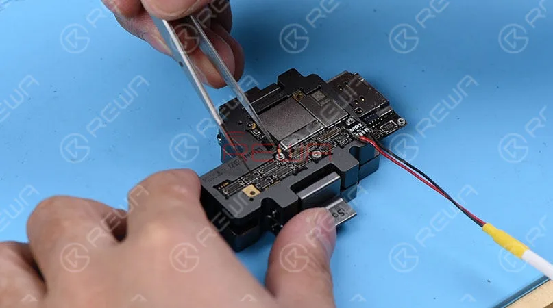
Attach the upper layer and the lower layer to the test fixture and get the phone powered on with tweezers. Current reading on the ammeter jumps to 100mA and then stays still, which is abnormal. Connect the battery connector on the upper layer and powered on. Current reading on the ammeter is normal. Judging by this, the upper layer has nothing to do with the won’t turn on issue and the fault is probably related to the lower layer. So our next move is to further measure the lower layer.
Step 4: Fault Confirming
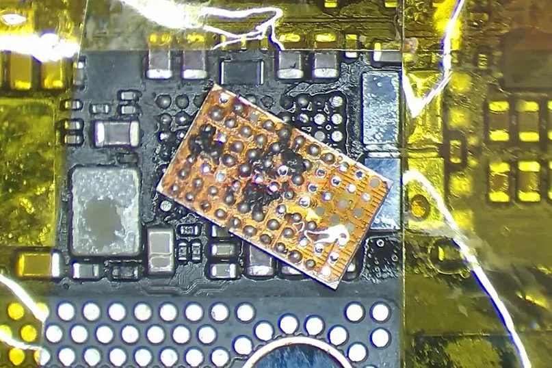
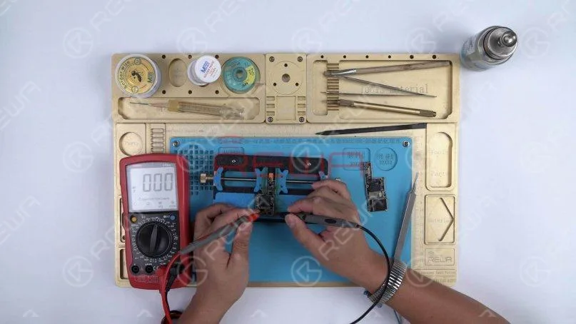
Run diode mode measurement of capacitors around the moldy IC U3400, and there is no short-circuit problem around U3400. Continue to run diode mode measurement of the third space PCB. The measured value of Pin S30 is 40, which is abnormal. Since Pin S30 is connected directly to Pin L4 of U3400, the fault is probably related to U3400. So the next thing we do is to check U3400. First, remove U3400 with Hot Air Gun. We can see that U3400 and its bonding pad have mildewed severely. Therefore, we need to replace it with a new IC.
Step 5: Fault Clearing
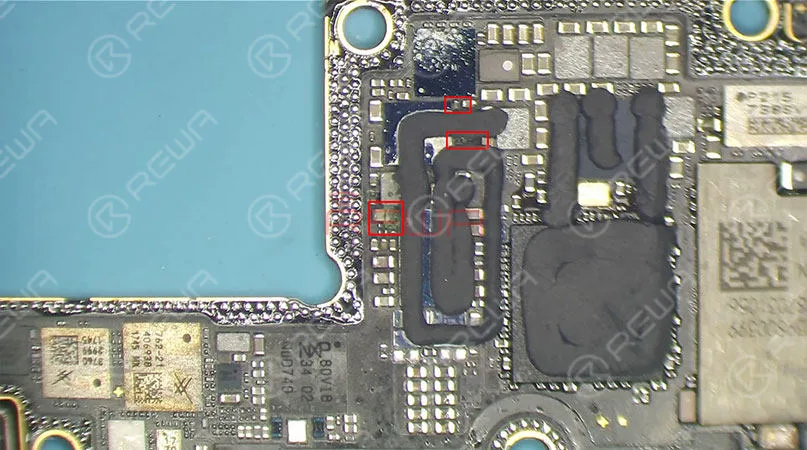
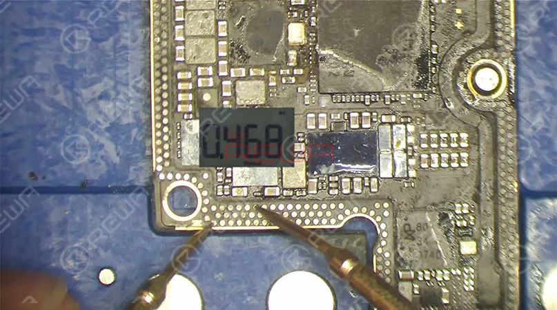
When cleaning the bonding pad, we find that three components around U3400 have been subjected to different degrees of corrosion. We need to remove the three components one by one and solder new components to corresponding positions. After that, we can move on to IC soldering. Once done, wait for the lower layer to cool for 5 minutes. Again, run diode mode measurement of Pin S30 on the third space PCB. The measured value is 468, which is normal now.
Step 6: Test
Now, attach the upper layer and the lower layer to the test fixture. Current reading on the ammeter is normal this time and the phone turns on normally.
Step 7: Reballing
In this step we will use a very useful tool, known as iPhone X specialized reballing mold. It can help us complete the reballing process perfectly.
Step 8: Motherboard Recombining
With the help of iPhone X specialized Heating Platform, the motherboard recombining process is very easy and efficient. Wait for the motherboard to cool for 10 minutes.
Step 9: Assemble & Test
Now we can assemble the phone and test. Press the power button to turn on the phone. The phone turns on normally. Fault cleared. Warm tips: get the phone full assembled after confirmation of fault clearance. iPhone X won’t turn on caused by water damage fixed perfectly.
For more iPhone X water damaged troubleshooting details, please visit here: REWA TIENDA ONLINE IS OPEN, EQUIPPED WITH ALL TOOLS USED IN THE BLOG, READY TO POWER YOUR REPAIR BUSINESS?
La tecnología de carga inalámbrica se ha impuesto en los smartphones actuales. La carga inalámbrica parece tan cómoda y sencilla que cada vez más gente está deseando probarla y utilizarla en su vida diaria. Sin embargo, la realidad no siempre es tan fluida como se espera. Colocas el iPhone en la almohadilla de carga, pero no pasa nada. En este artículo, compartiremos cómo arreglar un iPhone X que no se carga de forma inalámbrica.
1. Comprobación de la placa base
En primer lugar, realice una inspección cosmética de la placa base. La placa base no está deformada ni dañada por el agua.
2. Ensamblar y probar
A continuación, monte el teléfono y pruébelo. Pulse el botón de encendido para encender el teléfono. El teléfono se enciende normalmente.
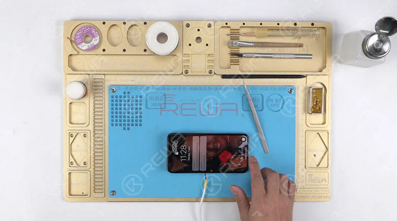
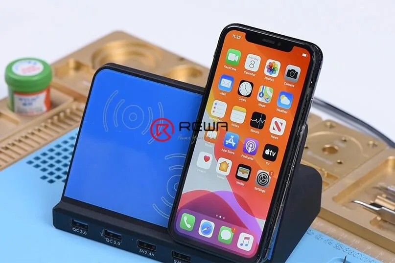
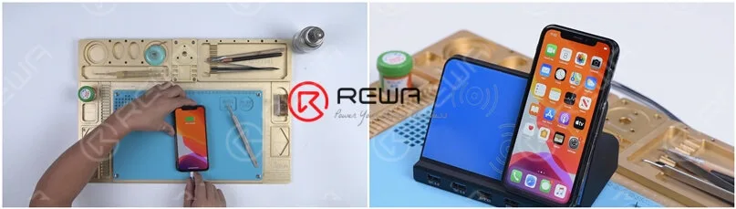
Enchufa el cable de carga. El teléfono se puede cargar con el cable de carga. Coloca el teléfono en un cargador inalámbrico. El teléfono no se puede cargar de forma inalámbrica.
Tenemos que centrarnos en los circuitos de carga inalámbrica pertinentes.
3. Medición en modo diodo del conector de carga inalámbrica
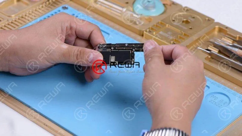
Desmonte el teléfono y saque la placa base. Retire primero la esponja antipolvo que cubre la placa. A continuación, realice una medición en modo diodo del conector de carga inalámbrica. El valor medido es normal, lo que indica que los circuitos de carga inalámbrica relevantes en la almohadilla de unión son normales. Pasemos ahora a los circuitos de carga inalámbrica de la capa inferior.
4. Separación de la placa base
Lo primero que haremos será separar la capa superior de la inferior. Colocamos la placa base sobre la plataforma de calefacción y colocar un tornillo en el orificio de la placa base. Así que podemos desmontar la capa superior de manera eficiente después.
Caliente la placa base durante 2 minutos en la plataforma de calentamiento a 165℃. Una vez calentada, retire la capa superior con unas pinzas y, a continuación, la inferior.
5. Inspección de la capa inferior
Realiza una inspección cosmética de la capa inferior. Nada va mal. Realiza una medición en modo diodo de los condensadores alrededor del CI de carga inalámbrica. A juzgar por el valor medido, no hay cortocircuito. Continúe midiendo los diodos alrededor del CI de carga inalámbrica. El valor medido también es normal.
6. Sustitución del CI de carga inalámbrica
Intentemos sustituirlo por un nuevo IC de carga inalámbrica y veamos cómo funciona.Fije la capa inferior al soporte de la PCB y aplique un poco de fundente en pasta al IC de carga inalámbrica. Calentar con Pistola de aire caliente QUICK 990 AD a 360℃, flujo de aire 3 durante aproximadamente 1 minuto. Retire el IC de carga inalámbrica de la placa con unas pinzas.
Continúe aplicando pasta de soldadura de temperatura media a la almohadilla adhesiva. Calentar con soldador a 365℃ para limpiar la almohadilla de unión. Una vez hecho esto, caliente con pistola de aire caliente a 360℃, flujo de aire 3 para limpiar la almohadilla de unión con colofonia empapada. mecha de soldadura.
A continuación, limpie con un limpiador de PCB y aplique un poco de fundente en pasta a la almohadilla de unión.
Consigue un nuevo IC de carga inalámbrica en la posición correcta y suelda con la pistola de aire caliente QUICK 990 AD en 360℃, flujo de aire 3.
7. Restauración de la placa base
Lo siguiente que tenemos que hacer es soldar las dos capas. Limpia la almohadilla de unión antes de soldar. Una vez hecho esto, haz que la almohadilla de unión vuelva a estar limpia.
Una vez terminado, coloque la capa inferior en la plataforma de calentamiento. Aplique un poco de fundente de pasta BGA en la almohadilla de unión y coloque la capa superior en la posición correcta. Calentar durante 2 minutos en la plataforma de calentamiento a 165℃.
Ahora podemos montar el teléfono y probarlo.
8. La carga inalámbrica no funciona en el iPhone X se ha solucionado con éxito
Instale la placa base y conecte el conjunto de la pantalla. Pulse el botón de encendido para encender el teléfono. El teléfono se enciende normalmente.Coloque el teléfono en un cargador inalámbrico y el teléfono se puede cargar de forma inalámbrica.
Conclusión:
La carga inalámbrica del iPhone X no funciona. Enchufa el cable de carga y prueba. El teléfono se puede cargar con el cable de carga. Así que tenemos que centrarnos en los circuitos de carga inalámbrica pertinentes. Compruebe los componentes relevantes de carga inalámbrica alrededor del IC de carga inalámbrica. Todo va bien. Pruebe a sustituirlo por un nuevo circuito integrado de carga inalámbrica y el problema se habrá solucionado. Academia REWA.
Our repair case today is about repairing an iPhone X that won’t charge but with the lightning bolt showing up.
First of all, let’s get the motherboard installed and test. The phone turns on normally. Plug the charging cable and the lightning bolt shows up. However, there is no charging current on the ammeter. Judging by this, the motherboard can detect the power adapter whereas the phone won’t charge.
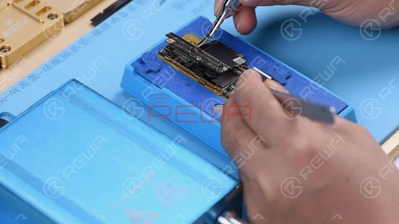
Since the housing, the battery, and the charging port flex cable used for the test are known-good parts, we need to focus on the charging circuit on the motherboard. The first thing we need to do is to separate the upper layer from the lower layer. Place the motherboard on the heating platform and fit a screw into the screw hole on the motherboard. So we can take down the upper layer efficiently afterward. Heat the motherboard for 2 minutes on the heating platform at 165℃.
Remove the upper layer and lower layer with tweezers.
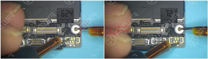
Run diode mode measurement of Pin 2 and Pin 3 on the battery connector J3200. The measured value is normal.
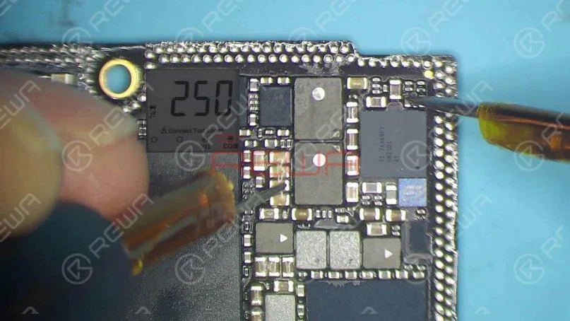
Continue measuring TIGRIS_LX between charging IC U3300 and Q3350. The measured value is 250, which is abnormal. The normal value should be 0. Judging by the measured value, TIGRIS_LX has open-circuited.
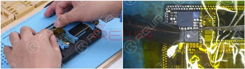
L3341 and L3340 are connected in series on the circuit. The open-circuited condition indicates that the two inductors might have been pseudo soldered or damaged. We need to replace the two damaged inductors with new inductors. Attach the upper layer to the PCB holder and stick high-temperature tape on components around. Heat with QUICK 990AD Hot Air Gun at 300℃ and airflow 3. Remove black adhesive around the two inductors.
Once done, apply some paste flux to the two inductors. Heat with Quick 990AD Hot Air Gun at 360℃ and airflow 3.
Pry up the two inductors carefully with the pry knife.
Continue to apply some medium-temp solder paste to the two bonding pads. Tin the two bonding pads with Soldering Iron at 365℃. Then clean black adhesive on the bonding pad.
Continue to apply some paste flux to the two bonding pads. Get the two inductors in the right position, and solder with QUICK 990AD Hot Air Gun at 360℃ and airflow 3.
Clean with PCB cleaner afterward. Again, let’s run diode mode measurement of TIGRIS_LX between U3300 and Q3350. The measured value is 0, which is normal.
Now we need to attach the upper layer and the lower layer to the testing fixture and test. Firstly, clean the bonding pad.
Then attach the upper layer and the lower layer to the testing fixture.
Get the charging port flex cable connected. Then get the screen and the battery connected.
Plug the charging cable. The charging current on the ammeter is 860mA, which indicates that the phone can be normally charged.
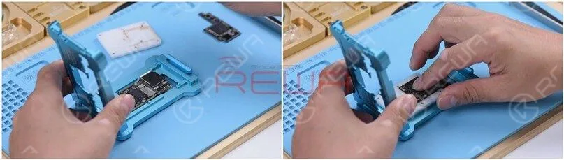
The next thing we need to do is to solder the two layers together. We need to get the lower layer reballed first. Put the lower layer into the reballing moldand get the BGA Reballing Stencil in position.
Place the mold onto the base. The stencil is tightly attached to the lower layer because of the magnetic structure of the base. Then we smear some low-temp solder paste on the stencil and wipe off excess solder paste with a lint-free wipe.
After reballing, take the mold down from the base and remove the reballing stencil. Heat the lower layer on the heating platform at 165℃. Once solder balls have shaped up completely, power off the heating platform.
Cool for 5 minutes. Apply some BGA Paste Flux to the bonding pad and get the upper layer in position. Then power on the heating platform. With the temperature reaching 165℃, continue heating for 2 minutes.
Turn the power off and cool for 5 minutes. Then take down the motherboard from the heating platform. Please check carefully to make sure that the two layers have been soldered together perfectly. Now we can assemble the phone and test. Get the motherboard installed and display assembly connected. Plug the charging cable. The lightning bolt shows up on the screen. The charging current on the ammeter is also normal. The fault is cleared.
Conclusión:
The lightning bolt shows up on the iPhone X screen while there is no charging current on the ammeter. Check the charging circuit on the motherboard and one rail has open-circuited. Replace the two inductors on the rail and the problem is fixed.
If you are looking for more in-depth content and want to study systematically, please feel free to visit our academia.
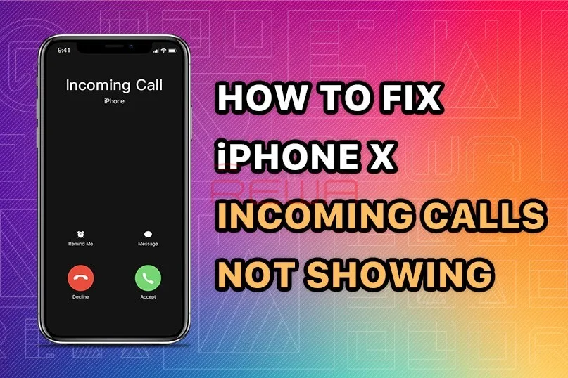
Some iPhone users may encounter such a problem, when the phone screen is turned off, we cannot receive the call.
Right now, there are few solutions to fix iPhone not responding in sleep mode when getting incoming calls.
The general repair process of a repair technician is to take out the motherboard, check PMU and baseband CPU, and then replace or re-solder the faulty component.
The whole repair process is complicated and difficult.
Now REWA LAB will show you a brand new ‘signal borrowing’ solution to fix this problem quickly and efficiently.
Problema
Here we have an iPhone X not responding in sleep mode when getting incoming calls. When we were trying to test the Sounds&Haptics function, we found all going well.
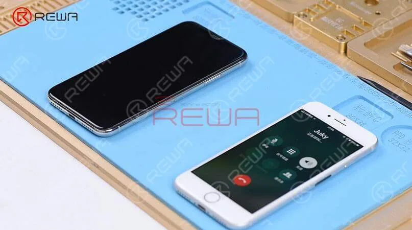
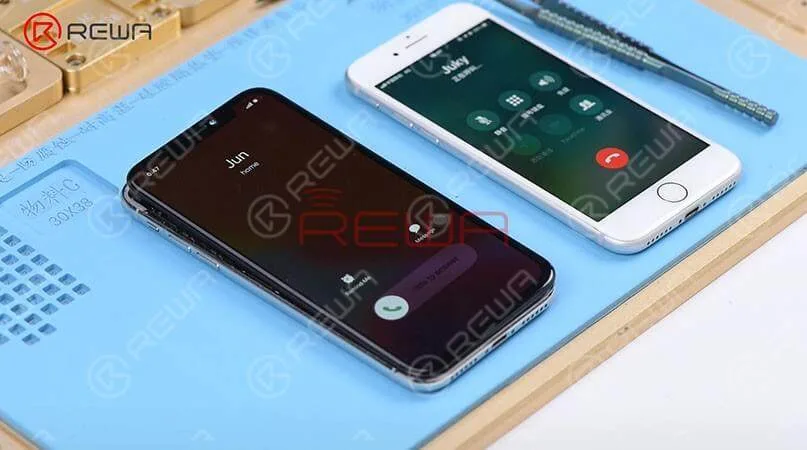
With the screen on, we placed a call to the phone using a known-good phone. And the decline and answer buttons appear on the screen.
However, if we turned the screen off, the phone is not responding at all. Then we pressed the power button to turn the screen on and we can see the incoming calls showing on display.
Diagnóstico
Judging by this, we can infer that relevant circuits of the baseband wake signal might have malfunctioned. So we took apart the phone, disconnected the battery, removed the display assembly, and took out the motherboard.
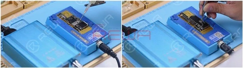
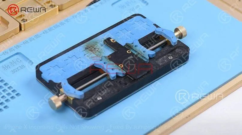
The following step is to attach the motherboard to the PCB Holder and then heat with Hot Air Gun at 200℃, airflow 3 to tear off the heat dissipation sticker on the backside of the motherboard.
Confirm the Signal Fault Location
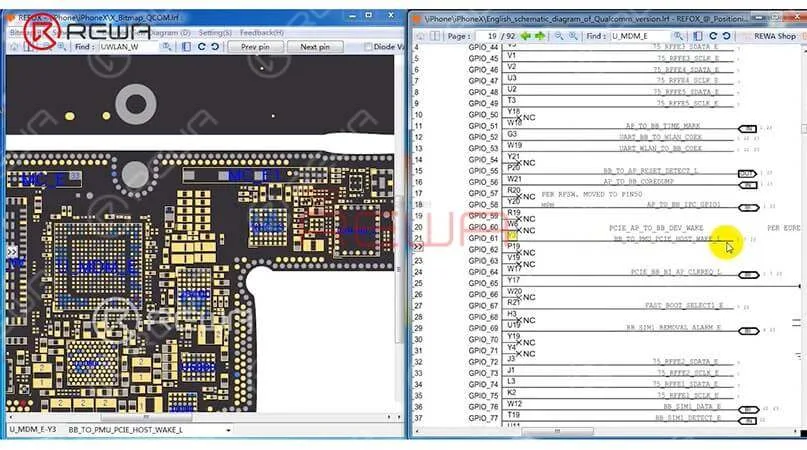
We can open the bitmap software in Refox and locate BB_TO_PMU_PCIE_HOST_WAKE_L first.
Since relevant circuits of the wake signal might have malfunctioned, so we can try to borrow the wake signal from WiFi relevant circuits.
Borrow Signal by Jumping a wire
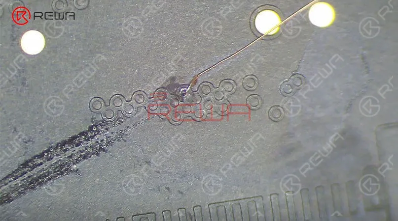
Then we need to locate WLAN_TO_PMU_HOST_WAKE. And the following step is to connect PP101_E-1 (the test point of the baseband wake signal) with PP7611_W-1 (the test point of the WiFi wake signal) by jumping a wire.
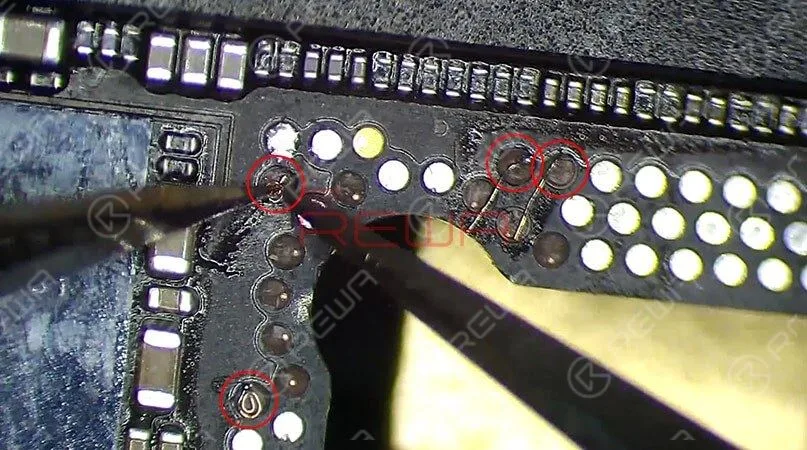
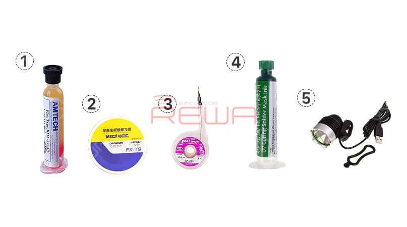
Before that, we need to scrape off the insulating coating on the two test points first, then apply some solder paste to the two bonding pads and heat with Soldering Iron at 365℃.
The next step is to tin the two bonding pads with solder paste and also to connect PP101_E-1 to PP7611_W-1 with 0.02mm Enameled Copper Wire.
Finally we need to coat the wire with the UV Curable Solder Mask.
Assemble the Phone and Test
Now we can assemble the phone and test. We got the motherboard installed and displayed assembly connected, then connected the battery.
Then pressed the power button to turn on the phone inserted the SIM card. After that, with the screen off, we tested again. And we found all going well.
PS: The repair case of this blog is applicable to the QCOM version, which might be a reference for the Intel version as a repair method.
iPhone gets stuck on the Apple logo, which usually means that there is a problem with the operating system or hardware of the phone.
Today, we will show you a rare case of iPhone X stuck on apple logo, and teach you how to diagnose and fix the problem step by step.
Inspección cosmética
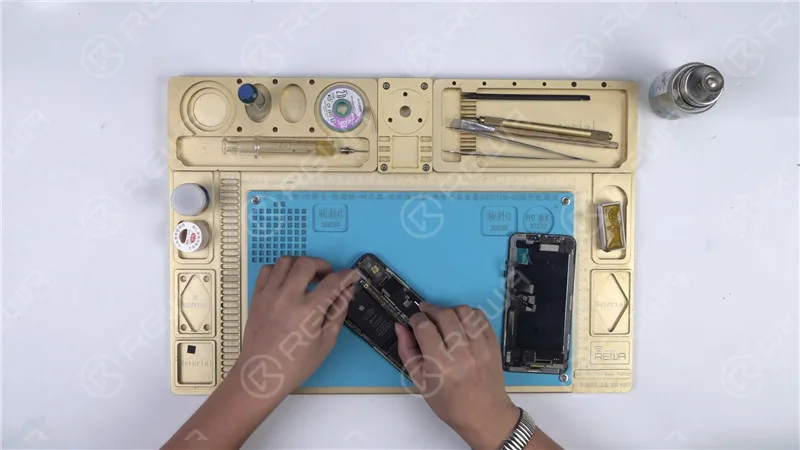
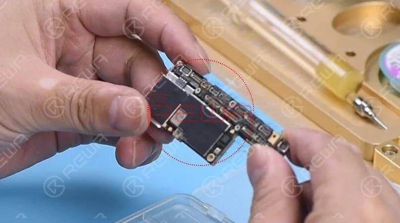
As we always do, we should run a cosmetic inspection of the motherboard first.
Check out the condition of the motherboard, whether it is deformed or water damaged.
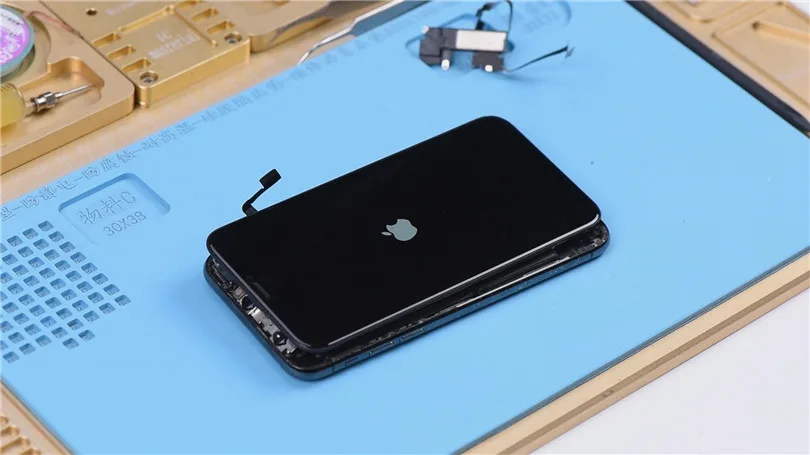
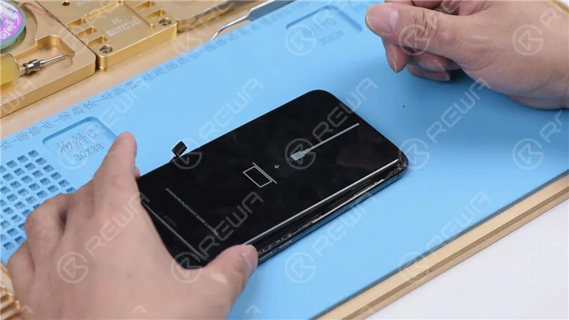
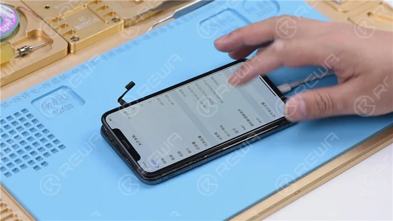
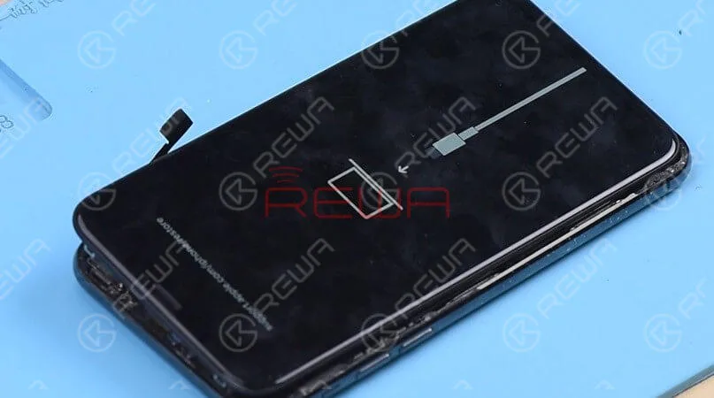
Then get the motherboard installed, the phone enters into recovery mode automatically.
Judging by this, the motherboard comes with restore failure. Therefore, the phone cannot enter into the system normally.
Diagnóstico
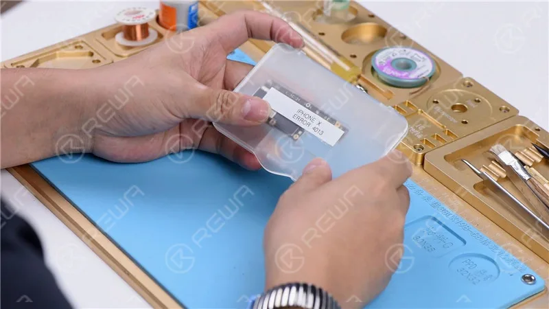
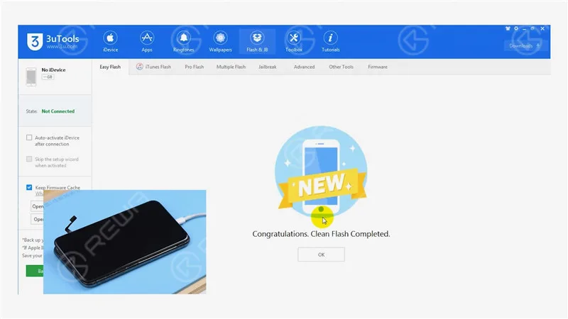
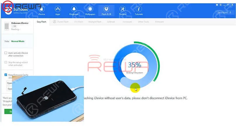
Let’s restore the phone with 3U Tools and check whether it comes with error 4013.
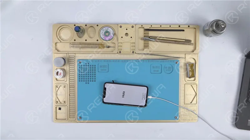
The phone can be normally activated after restore.
Next, check baseband info in the settings. If it shows normal, we can confirm now that the motherboard is normal. The fault is probably related to other parts.
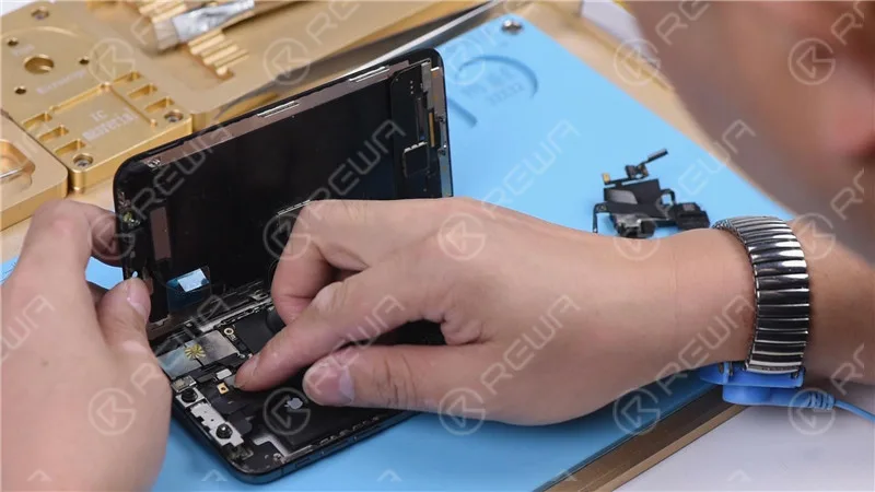
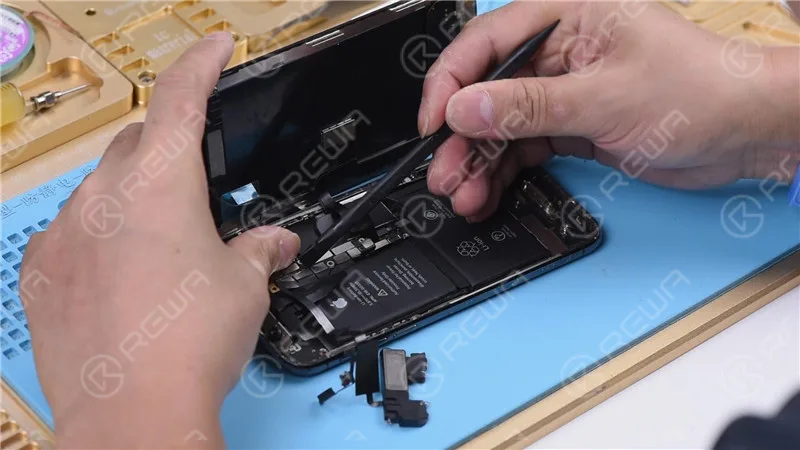
Get the earpiece speaker and sensor flex cable and front camera flex cable installed.
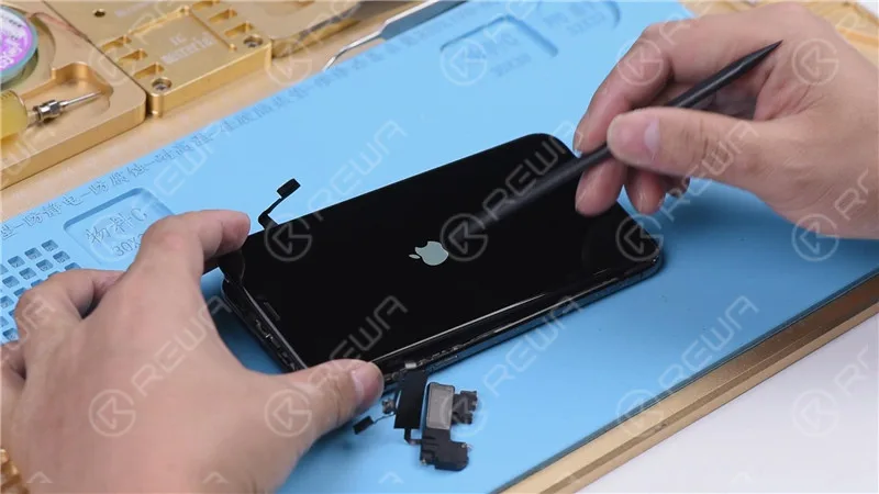
Turn on the phone, the phone is stuck on the Apple logo and keeps restarting.
Judging by this, the fault is related to the earpiece speaker and sensor flex cable or the front camera flex cable.
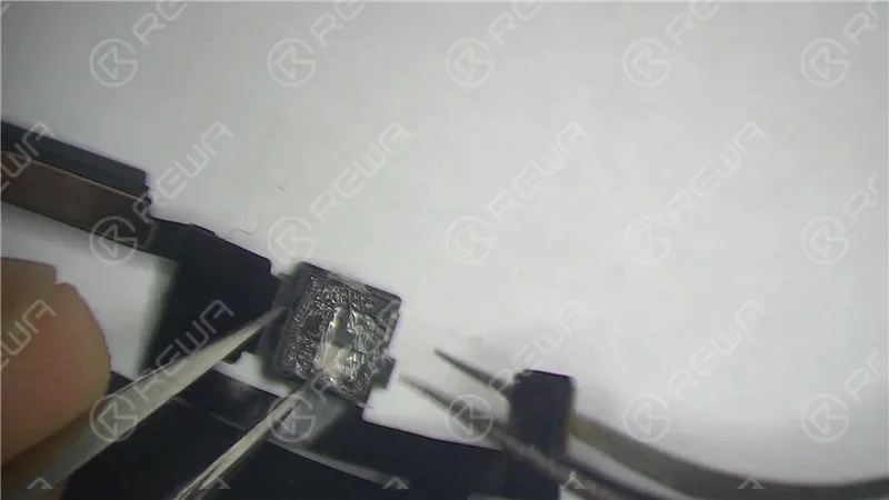
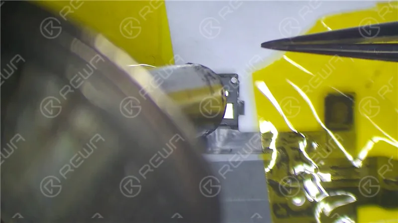
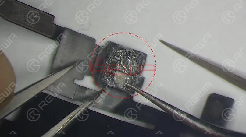
Check the earpiece speaker and sensor flex cable carefully, we find that the Flood illuminator module is moldy.
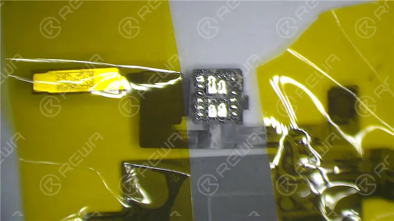
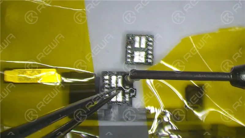
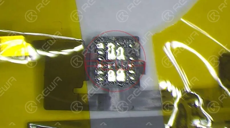
Remove the Flood illuminator module, we can see that its bonding pad is severely corroded.
That’s what’s causing the problem.
Maintenance
The next section will explain the detailed repair steps:
Apply some paste flux to the bonding pad.
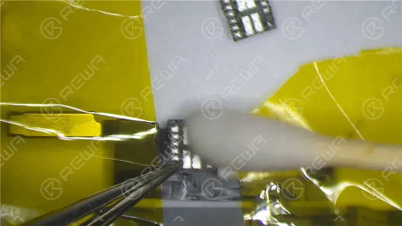
Clean the bonding pad with Soldering Iron.
Apply solder paste to the severely corroded pad.
Limpiar después con PCB Cleaner.
Apply some paste flux to the bonding pad.
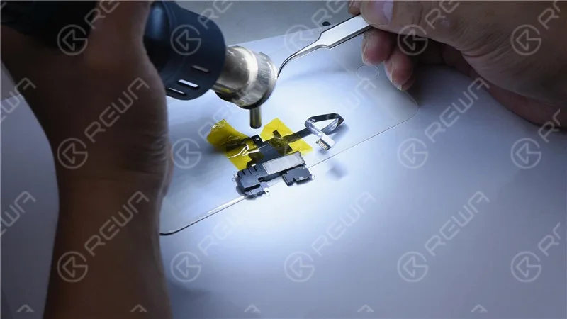
Get the Flood illuminator module in the right position.
Solder it with Hot Air Gun.
Prueba
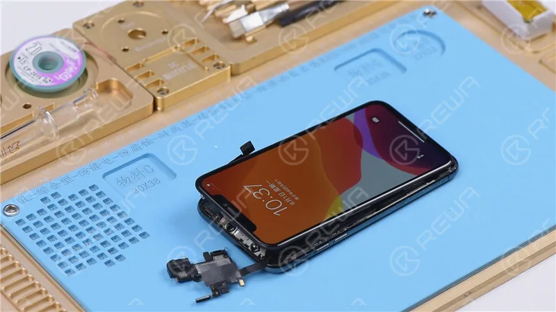
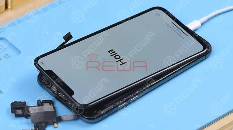
Get the earpiece speaker and sensor flex cable installed, then assemble the phone.
The phone turns on normally. Since the two flex cables were not connected during the previous restore, we need to restore again with the two connected.
Restore the phone with the help of 3U Tools.
Once completed, the phone enters the system normally, and Face ID works normally.
El proceso de reparación requiere no sólo conocimientos teóricos profesionales, sino también una gran habilidad manual.
Coloque una capa inferior en buen estado en el banco de pruebas y, a continuación, coloque la capa superior.
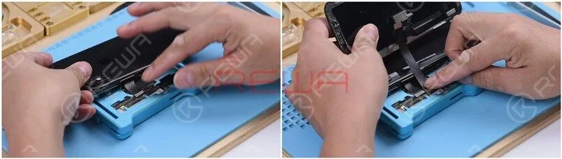
Conecta el conjunto de la pantalla.
Al ejecutar la prueba, podemos encontrar que el teléfono se enciende normalmente y la función táctil también es normal.
A juzgar por esto, el problema del tacto se debe a la capa inferior.
Intercambio de tableros
Como la capa inferior está muy deformada, tenemos que trasplantar la CPU de banda base, la EEPROM de banda base y el chip NFC de la capa inferior original a una nueva capa inferior.
Para más detalles, consulte el vídeo que figura a continuación:
Después de cambiar la placa, debemos ejecutar la prueba de nuevo mediante el uso de Test Fixture.
Conecte el conector de la batería con la fuente de alimentación de CC.
Luego enciende la placa base con unas pinzas.
Aquí podemos encontrar el número de serie del IMEI y el firmware del módem, lo que indica que el intercambio de la capa inferior se ha completado con éxito.
Recombinación de placas base
Lo siguiente es soldar las dos capas.
He aquí los siguientes pasos:
Fije la nueva capa inferior al molde de reballing especializado.
Cubrir la nueva capa inferior con la plantilla de reballing a juego.
Unte un poco de pasta de soldar de baja temperatura en la plantilla.
retire con cuidado la plantilla de reballing.
Continúe colocando la nueva capa inferior sobre la plataforma calefactora.
Esperando a que se derrita la pasta de soldadura, empiezan a formarse las bolas de soldadura.
Esperar a que la capa inferior se enfríe durante 10 minutos.
Aplique BGA Paste Flux al tercer espacio PCB, coloque la capa superior en posición.
Calentar durante 1 minuto en la plataforma calefactora a 160 grados.
Con la capa superior hundiéndose y el Paste Flux fluyendo, las dos capas se han soldado con éxito.
Espere a que la placa base doblemente apilada se enfríe durante 5 minutos.
Restauración True Tone
Cuando terminemos de reparar la placa base, es hora de trasplantar las piezas.
REWA cuenta con años de experiencia en la prestación de servicios de venta al por mayor de una amplia gama de productos electrónicos, como piezas de recambio para teléfonos móviles y baterías de repuesto.
Nos adherimos al principio de ”Calidad por encima de todo” a través de todo el proceso de producción y pruebas. Estos son algunos de nuestros productos seleccionados:
A continuación fijaremos el True Tone de la nueva pantalla.
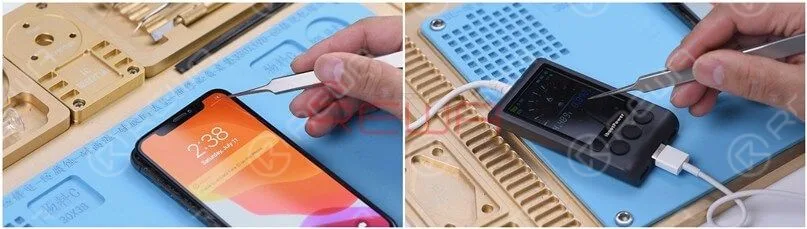
Conecte la pantalla original con el módulo ampliado de visualización, lea los datos de la pantalla original con el Programador de reparación True Tone.
Una vez hecho esto, conecte la nueva pantalla con el módulo ampliado de pantalla.
Escribe los datos almacenados de la pantalla original en la nueva pantalla.
Desvinculación Wi-Fi
Debido a que no nos ocupamos de la Wi-Fi IC en la placa base, el interruptor Wi-Fi no se puede conmutar.




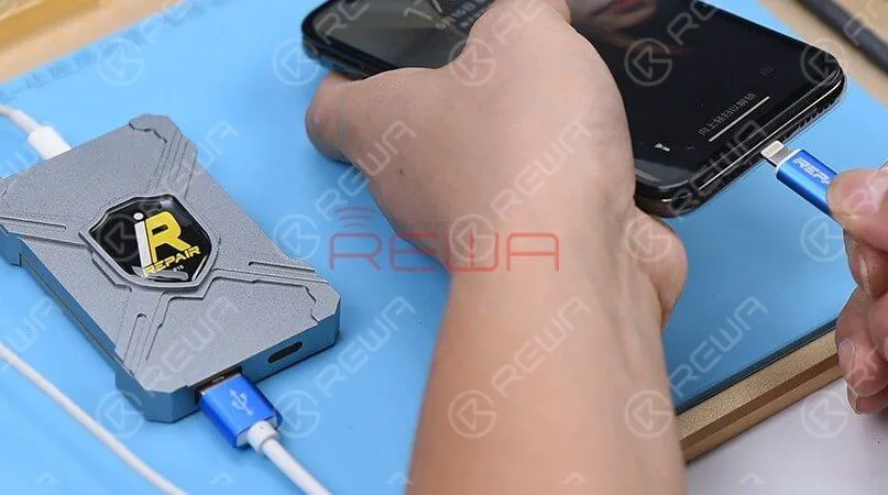
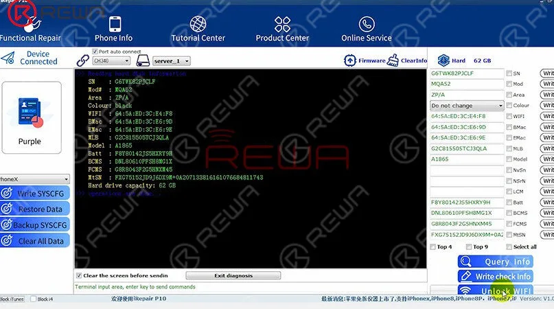

 English
 Español
 Français
 Deutsch
 Italiano