Tag: macbook

  • MacBook Pro 2017 Won’t Turn On Troubleshooting Guide

    MacBook Pro 2017 Won’t Turn On Troubleshooting Guide

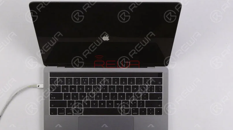
    As the latest MacBook model in 2017, Macbook Pro 13″ (A1708) is different from previous models in exterior design and interior logic board circuit construction. Which also increases difficulty of its repairability – it scored a 2 out of 10 on ifixit repairability scale (10 is the easiest to repair). This time we will share with you a complex MacBook won’t turn on repair case caused by multiple faulty components like capacitors, inductors, etc..

    Problem

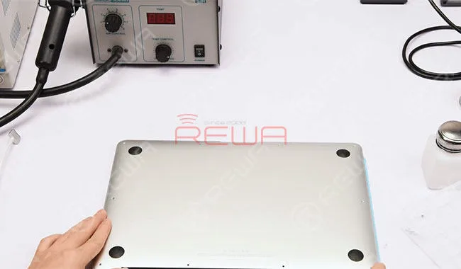
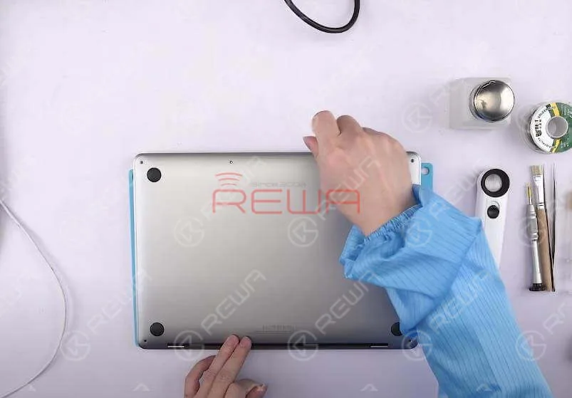
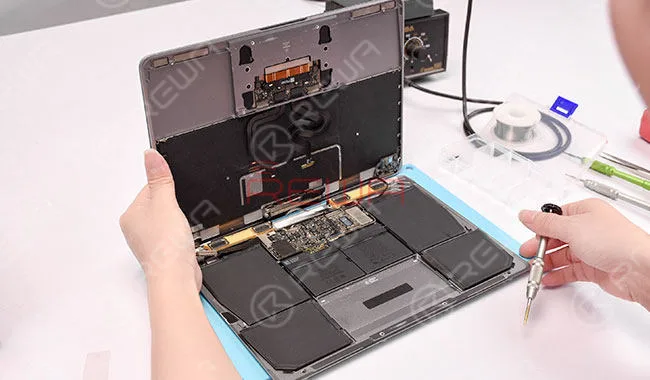
    Press power button, and the MacBook won’t turn on. Confirm the serial number on the lower case first. Pop free the clips securing the lower case to the chassis. Pull the lower case away from the hinge area to separate. Then remove the lower case.

    Press power button, and the MacBook won’t turn on. Confirm the serial number on the lower case first. Pop free the clips securing the lower case to the chassis. Pull the lower case away from the hinge area to separate. Then remove the lower case.
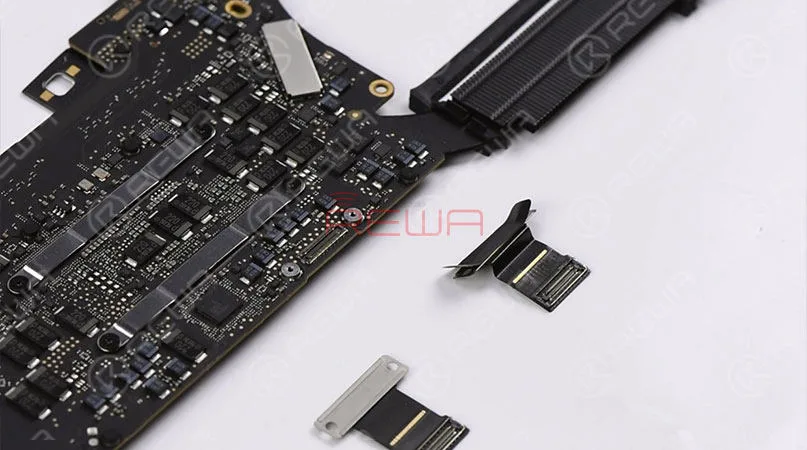
    Disconnect the battery and detach the logic board. Remove the SSD module. Then confirm the board number of logic board.

    Diagnosis

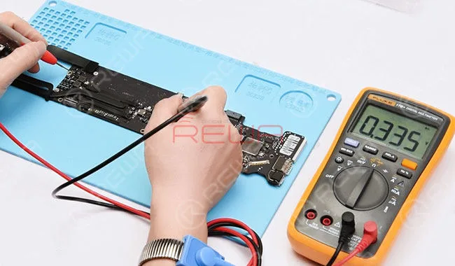
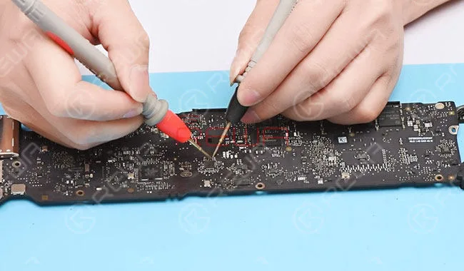
    Run diode mode measurement of main power supply inductor L7030. The measured value is 348, which is normal. Switch to voltage mode. Plug in AC adapter and measure the voltage of L7030. The measured voltage value is 0V, which is abnormal. Normal voltage value should be around 13V.
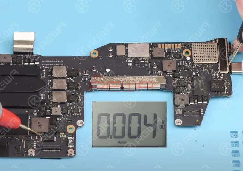
    Run diode mode measurement of main power supply inductor L7030.

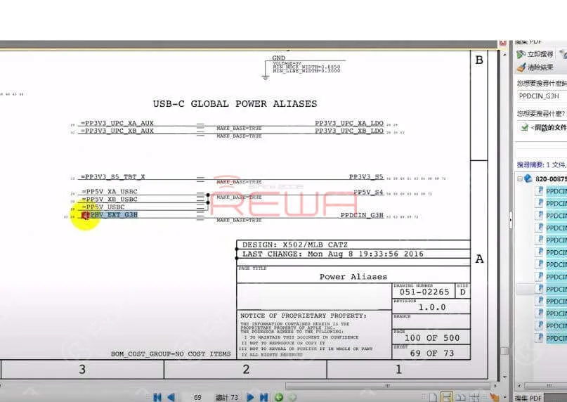
    Roll out the maintenance drawing and bitmap. Confirm L7030 relevant circuit PPDCIN_G3H (also known as =PPHV_EXT_G3H).
    Roll out the maintenance drawing and bitmap. Confirm L7030 relevant circuit PPDCIN_G3H (also known as =PPHV_EXT_G3H).
    Confirm the working condition of U3100. Confirm U3100 main power supply Pin H1 VIN_3V3 (also known as =PP3V3_G3H_UPC_XA). =PP3V3_G3H_UPC_XA is converted into PP3V3_G3H via R3000.

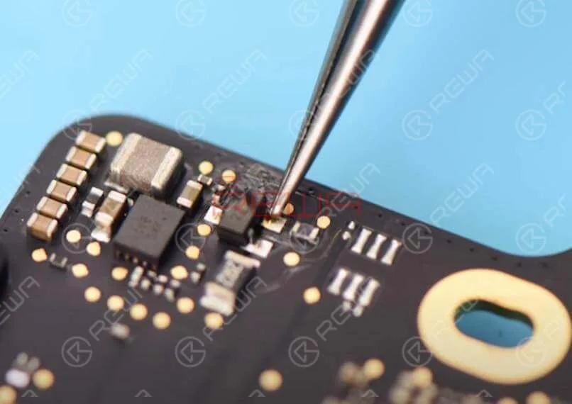
    Then confirm the power supply source of PP3V3_G3H. PP3V3_G3H is outputted from U6990 via L6995. Locate U6990 with bitmap. Then locate the corresponding position of U6990 on the logic board. Traces of damage can be found on chips around U6990. Confirm the working condition circuit of U6990 with drawing. Then locate L6995 with bitmap.
    MacBook Pro 2017 Won't Turn On Troubleshooting Guide

    Switch to diode mode and run diode mode measurement of L6995. The measured value is 342, which is normal. Roll out the drawing and locate the Pin 2 SUP of U6990 main power supply (also known as PPVIN_G3H_P3V3G3H). PPVIN_G3H_P3V3G3H is converted from compound diode D6905. Locate D6905 with bitmap. Then locate the corresponding position of D6905 on the logic board.
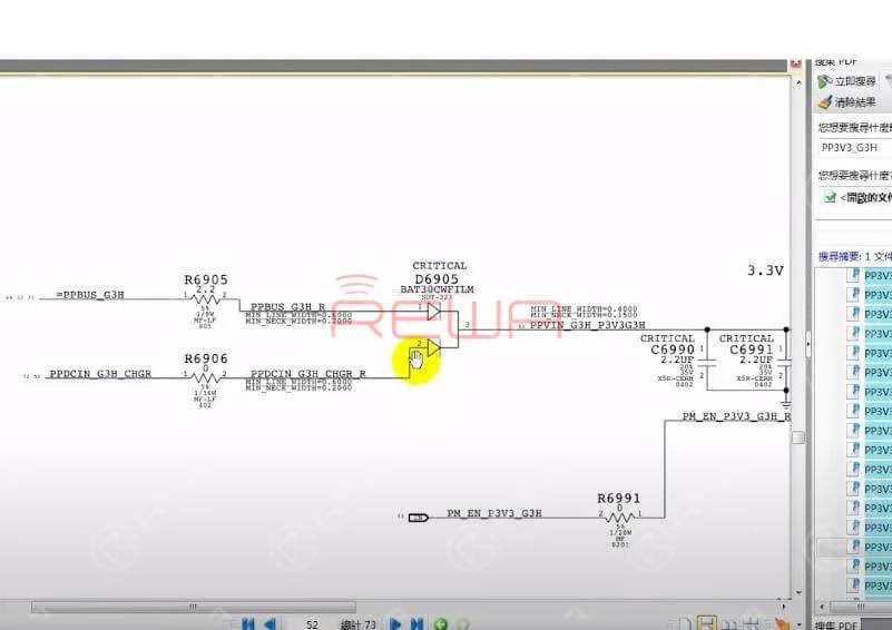
    Locate D6905 with bitmap. Then locate the corresponding position of D6905 on the logic board.

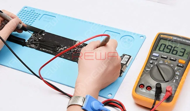
    Run diode mode measurement of D6905 Pin 3. The measured value is 0, which indicates short-circuited condition. Run diode mode measurement of D6905 Pin 1. The measured value is 98, which is lower than normal value. Run diode mode measurement of D6905 Pin 2. The measured value is 526, which is normal.
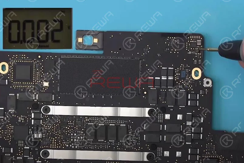
    Run diode mode measurement of D6905 Pin 3.

    We can conclude that D6905 has been damaged.

    Troubleshooting

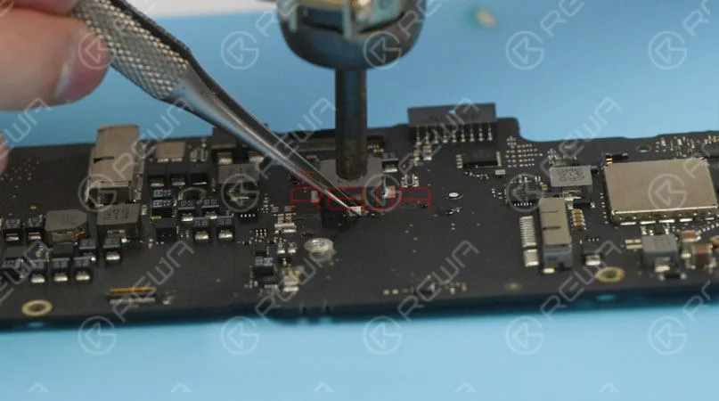
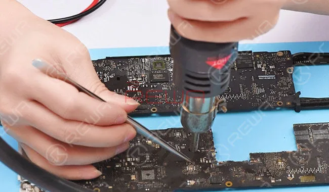
    Let’s detach D6905 first. Apply some BGA Paste Flux and detach D6905 with Hot Air Gun at 430℃. Clean with PCB Cleaner after the logic board has cooled enough.
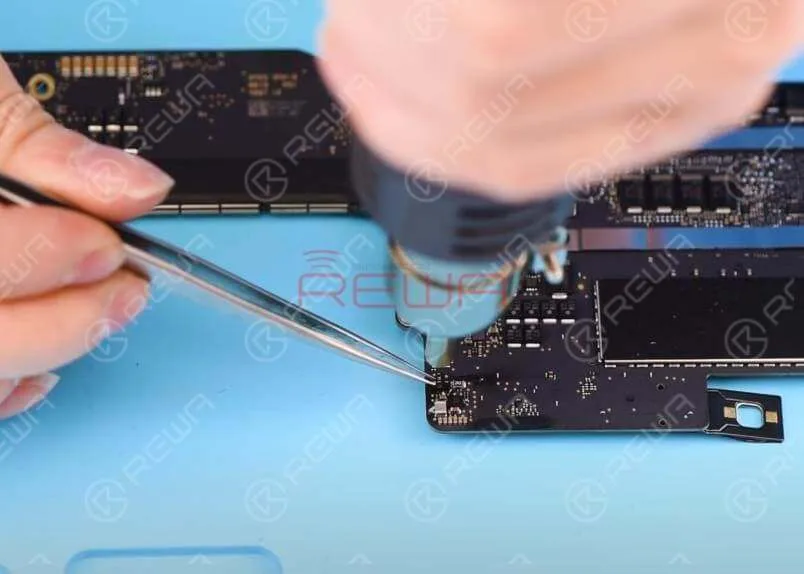
    Let’s detach D6905 first. Apply some BGA Paste Flux and detach D6905 with Hot Air Gun at 430℃.

    Run diode mode measurement of the D6905 detached bonding pad. The measured value of Pin 1 is 444, which is normal. The measured value of Pin 3 is 0, which indicates short-circuited condition. Confirm relevant circuit of D6905 Pin 3 power supply with drawing. The circuit consists of U6990, C6990 and C6991. Detach U6990 to check if the short-circuited condition can be solved.
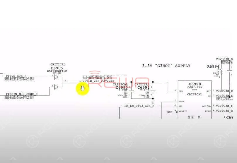
    Run diode mode measurement of the D6905 detached bonding pad.

    Apply some BGA Paste Flux and detach U6990 with Hot Air Gun at 430℃. Clean with PCB Cleaner after the logic board has cooled enough.
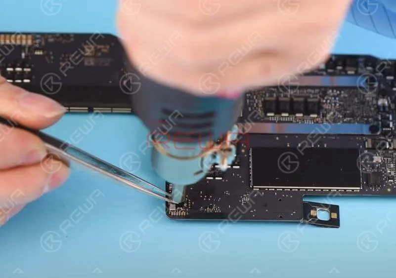
    Apply some BGA Paste Flux and detach U6990 with Hot Air Gun at 430℃.

    Run diode mode measurement of D6905 Pin 3 again. The measured value is 0, which indicates short-circuited condition. We can conclude that the faulty condition has nothing to do with U6990. Yet U6990 might has been damaged as well. The faulty condition might be related to C6990 and C6991.

    Detach C6990 first. Apply some BGA Paste Flux and detach C6990 with Hot Air Gun at 430℃. Clean with PCB Cleaner after the logic board has cooled enough.
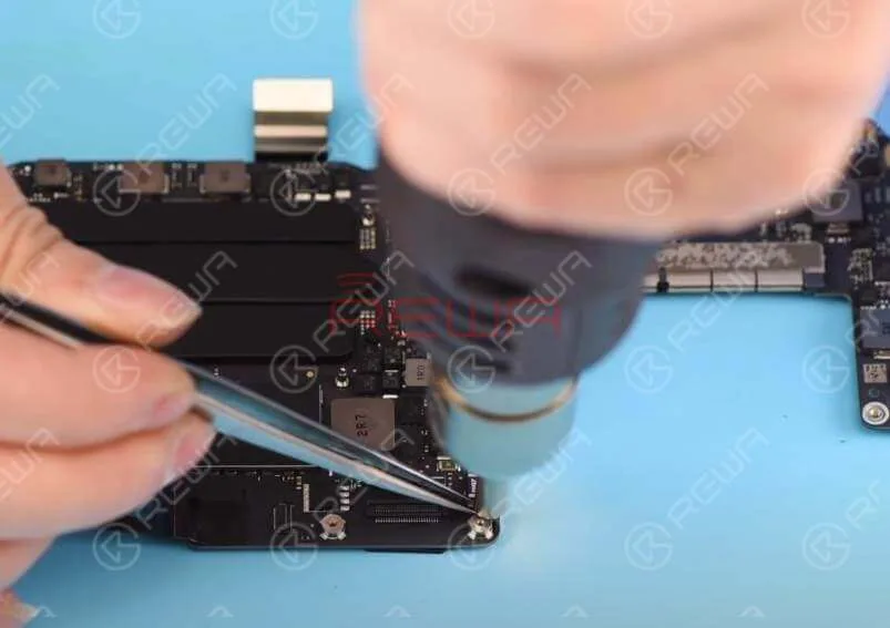
    Detach C6990 first. Apply some BGA Paste Flux and detach C6990 with Hot Air Gun at 430℃. Clean with PCB Cleaner after the logic board has cooled enough.

    Then run diode mode measurement of D6905 Pin 3 again. The measured value is 593, which is normal. We can conclude now that the faulty condition is related to C6990. Also, we need to replace with a new U6990. Let’s start with U6990 replacement.
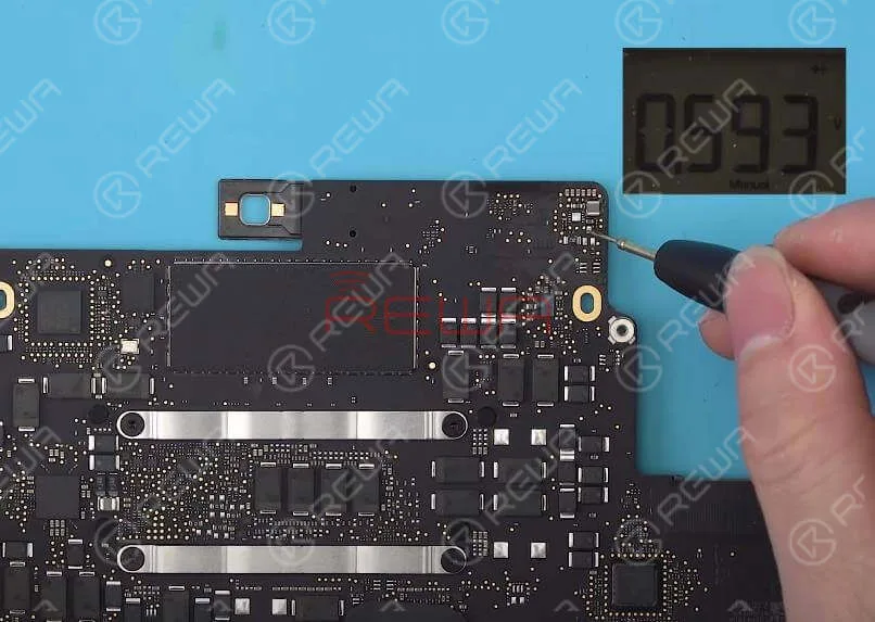
    Then run diode mode measurement of D6905 Pin 3 again. The measured value is 593, which is normal.

    Apply some BGA Paste Flux and solder with Hot Air Gun at 430℃. Clean with PCB Cleaner after the logic board has cooled enough. Then run diode mode measurement of D6905 Pin 3 again. The measured value is 531, which is normal.

    Next thing we do is to solder a new D6905. Apply some BGA Paste Flux and solder with Hot Air Gun at 430℃. For better soldering, add some low-melting point tins during the soldering process. Clean with PCB Cleaner after the logic board has cooled enough.

    Then run diode mode measurement of three pins on D6905 one by one. The measured value of Pin 1 is 437, which is normal. The measured value of Pin 3 is 533, which is normal. The measured value of Pin 2 is 531, which is normal.
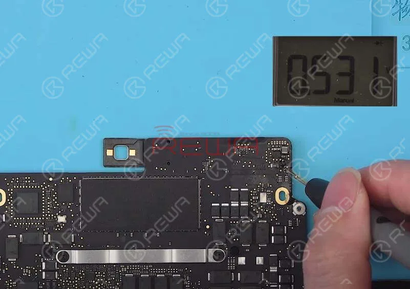
    Then run diode mode measurement of three pins on D6905 one by one. The measured value of Pin 1 is 437, which is normal. The measured value of Pin 3 is 533, which is normal. The measured value of Pin 2 is 531, which is normal.

    Next thing we do is to solder a new C6990. Apply some BGA Paste Flux and solder with Hot Air Gun at 430℃. Run diode mode measurement of D6905 Pin 3 again. The measured value is 533, which is normal.

    Plug in AC adapter and measure the voltage of D6905 Pin 3. The measured voltage value is 19V7, which is normal. Then measure the voltage of L6995. The measured voltage value is 3V4, which is normal. Measure the voltage of L7030. The measured voltage value is 13V, which is normal.
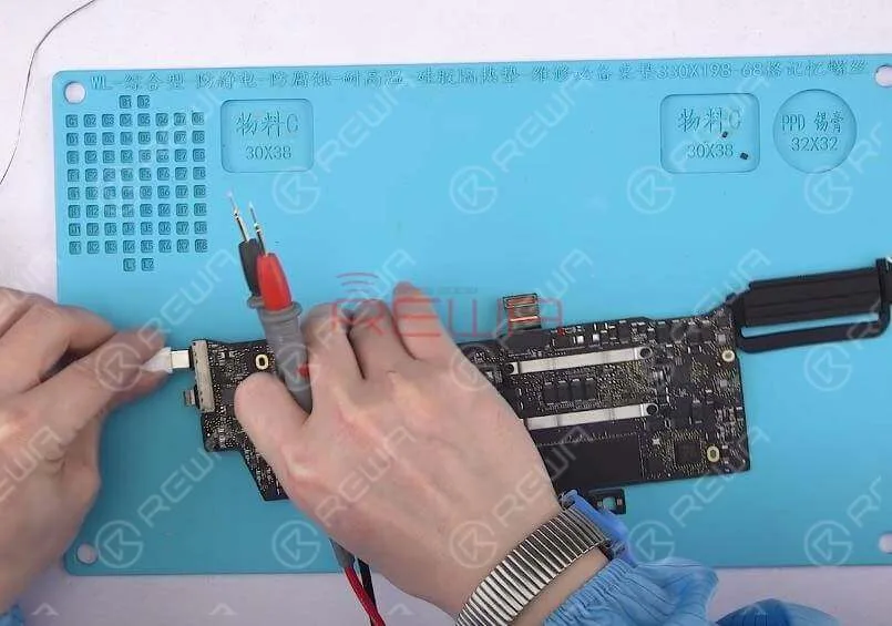
    Plug in AC adapter and measure the voltage of D6905 Pin 3. The measured voltage value is 19V7, which is normal. Then measure the voltage of L6995. The measured voltage value is 3V4, which is normal. Measure the voltage of L7030. The measured voltage value is 13V, which is normal.

    Measure the voltage of U3100 main power supply Pin H11 VBUS (also known as =PP20V_USBC_XA_VBUS). The corresponding measuring point is C3101. The voltage rises from 5V1 to 20V, which is normal. Then measure the voltage of logic board power supply group by group. All going well.

    Reassemble And Test

    Get the logic board mounted. Plug in AC adapter and power on. The MacBook turns on normally.Disconnect the power supply and insert the SSD. Plug in AC adapter and power on. The MacBook turns on normally.
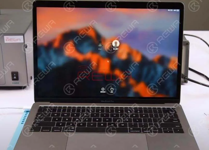
    Get the logic board mounted. Plug in AC adapter and power on. The MacBook turns on normally.Disconnect the power supply and insert the SSD. Plug in AC adapter and power on. The MacBook turns on normally.

    Disconnect the power supply and get the MacBook full assembled. Plug in AC adapter and power on. The MacBook turns on normally. Fault cleared.

    For detailed operation about MacBook Pro repair, you can also check out REWA YouTube Channel .

    REWA Academy

    Developed by REWA Technology,  REWA Academy  is a platform that provides repair technique learning, practical demonstration, and idea-sharing for practitioners in the electronic repair industry. Over the years, our teaching staff and R&D team have dedicated themselves to developing systematic repair training courses online and offline.
  • “The Best For The Brightest” – Last Rising Of This Gen MacBook Pro

    “The Best For The Brightest” – Last Rising Of This Gen MacBook Pro

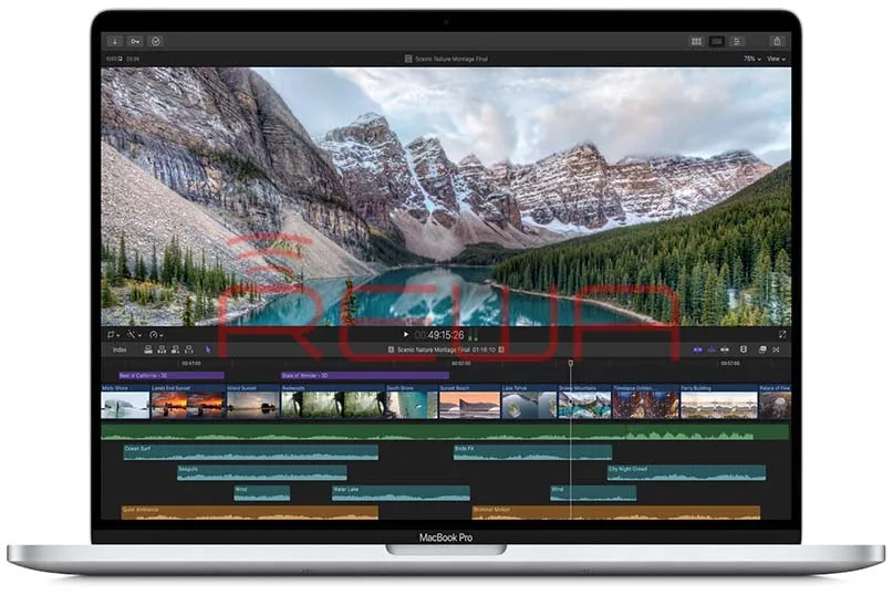
    “The best for the brightest”. When everyone thinks MacBook Pro will be delayed until next June, Apple releases the brand new 16-inch MacBook Pro on 13th Nov 2019. There is no launch event like “One more thing “. It is just released on Apple online store. Comparing with 2016 gen MacBook Pros, the 16-inch MacBook Pro brings not only a clear upgrade of screen size but also numerous features. Let’s take a look at it now.

    The Keyboard issue is finally fixed. Apple released the butterfly keyboard around 2016 and claimed how tiny it was. However, the butterfly keyboard always has different issues related to dust, crumb, and small particulate exposure. Now the 16-inch MacBook Pro comes with a “Magic keyboard” that is a big update to put Apple back in order to move forward. The new keyboard now has a full millimeter of travel which significantly increases user experience. Besides, the physical Esc key comes back as well, and it is the best stuff for programmers.

    Moving to the screen part, it’s not actually a full inch larger than old versions. Apple almost kept the original size and looks like it just put a 16-inch screen to a 15-inch model unibody. Just like every full display mobile phone. It is a giant, color-accurate retina screen. Generally, the 16-inch model is just slightly bigger than the 15-inch model, but you will not find unless you compare them side by side. What more we get? It’s the speaker. By using three speakers on each side, it probably be the best speaker in laptop world. Apple also has improved the microphone which comes with a three-mic “studio” array. It supposed to be better than most laptop’s microphones.

    "The Best For The Brightest” - Last Rising Of This Gen MacBook Pro

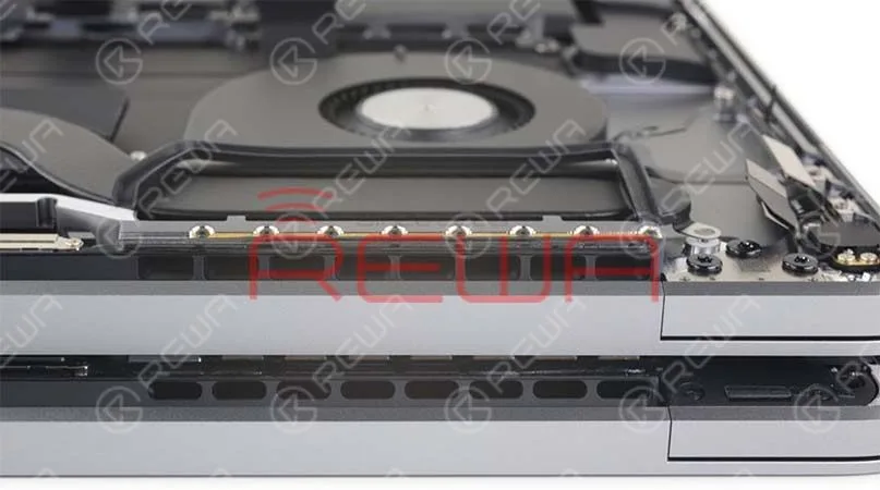
    Inside of 16 inch MacBook Pro

    Finally, the more powerful processor with brand new AMD graphic card series of Radeon Pro 5000M series which can be the best partner of video uploader. The price is not changed and just like previous 15 inch gen price. Looks like Apple really bring some amazing stuffs to consumers and it not looks like the luxury Apple we know. Anyone still remember Pro Stand? I believe the 16-inch MacBook Pro will be the last rising of this gen.

    "The Best For The Brightest” - Last Rising Of This Gen MacBook Pro

    Choose wisely…

    Let’s take a look of MacBook release timeline. Apple always puts new advanced technology in the last-gen before redesigning. For instance, Apple put force touch technology in 2015 gen MacBook Pro and the new MacBook Pro with touch bar was released in 2016. Back to 2012, Apple put retina screen in 2012 MacBook Pro the first time. So I predict Apple will release a brand new MacBook Pro next year with brand new design. Finally, is it the best MacBook Pro to buy at this moment? For myself, I will not purchase it as I still have 2017 15-inch version which just fine for my work. However, if you do not have Mac or still using 2014 or even more older model, the 16-inch will be a lovely choice for you. The powerful hardware combination and new design keyboard can directly increase working efficiency. Indeed, its is the most powerful MacBook Pro in the world.
    "The Best For The Brightest” - Last Rising Of This Gen MacBook Pro

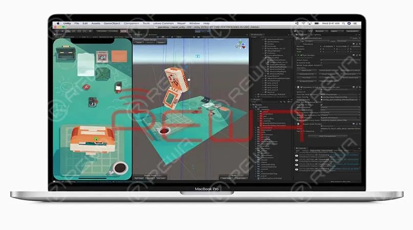
    16 inch MacBook Pro

    How’s your feeling of 16-inch MacBook Pro? Leave your comment to us.

  • Best Free Boardview Software for Logic Board Repair

    Best Free Boardview Software for Logic Board Repair

    Logic board repair relies heavily on accurate schematics and boardview software. For years, paid programs like ZXW and Wuxinji have dominated the repair industry—but not everyone wants to commit to expensive subscription tools, especially new technicians, DIY repairers, and refurbishers managing tight budgets.
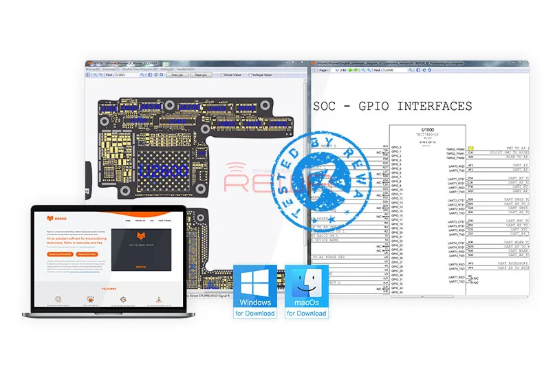
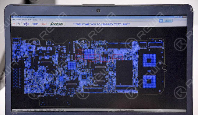
    That’s where REFOX, a fully free boardview software, has gained massive attention. Tested extensively by REWA repair masters and widely adopted in the industry, REFOX is becoming a go-to tool for technicians who need fast circuit tracing, powerful diagnostics, and cross-platform support without the cost.

    This guide gives you a complete, updated review of REFOX, who it’s for, and why it’s becoming the best free alternative to paid PCB analysis tools.

    What Makes REFOX Stand Out?

    Clean Interface With Full-Featured Functionality

    REFOX focuses on practicality—clean layout, intuitive tools, and simple navigation. Even beginners can quickly locate circuits, view nets, check values, and inspect traces with minimal learning time.

    Dual View: Boardview + Schematics Together

    One of REFOX’s strongest features is its synchronous double-view mode, allowing you to:

    • Load the schematic and boardview at the same time
    • Click a component to immediately see its related circuits
    • Jump between diagrams instantly for faster troubleshooting

    This dramatically cuts repair time for short circuits, open lines, and no power issues.

    Diode Mode & Voltage Reference Values

    REFOX lets you display component pins by:

    • Pin number
    • Diode value
    • Voltage value

    This is extremely useful for diagnosing common faults such as no power, dead boot, display failures, and charging issues.

    Complete iPhone Board Files

    REFOX includes boardview files covering:

    • iPhone 5 → Latest models (XR, XS, XS Max at the time of the article)

    Perfect for shops specializing in Apple repair or refurbishing.

    New Workflow Block Diagrams for Training

    The newly added block diagrams help beginners:

    • Understand component interconnections
    • Identify which areas control power, charging, baseband, touch, etc.
    • Follow step-by-step repair workflow

    These diagrams are also used in REWA’s logic board repair training programs.

    Customizable Color Themes

    You can adjust the boardview appearance using built-in color templates to suit your workflow—great for reducing eye strain during long repair sessions.

    A Long Way To Go

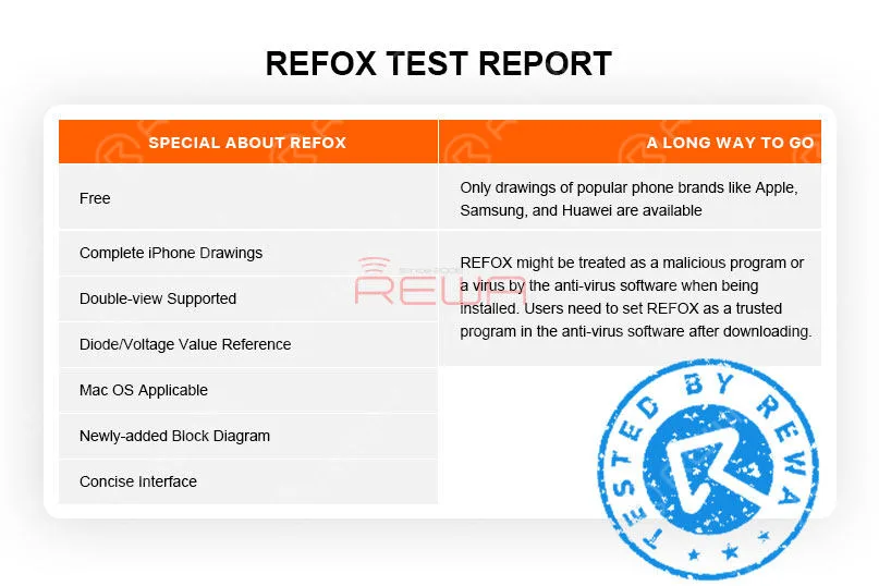
    1. Only drawings of popular phone brands like Apple, Samsung, and Huawei are available. There are still more brands for us to explore.

    2. According to REFOX, with schematics and board files encrypted, REFOX might be treated as a malicious program by the anti-virus software or the browser when being installed.

    Actually, REWA has been using and testing REFOX for several months and has found no internet security risks. Still, we hope that the next version can fix the bug.
    Refox Review - A Free Boardview Schematics Bitmap For Logic Board Repair

    Conclusion

    REFOX has now been updated to V3.25 and bugs of earlier versions have also been fixed.

    Although there is still room for improvement, we are proud to announce that REFOX can fully meet repair needs of repair technicians.

    What’s more, it is completely free.

    Therefore, we highly recommend this bitmap software to you.

    For those in need, please visit www.refoxteam.com to download the software.

    There are also some detailed operation videos for your reference on the official website.

    You can also visit REWA Youtube Channel to check the detailed description of Refox.

  • MacBook LCD Only Repair – Easy Fix with Air Slice Tool

    MacBook LCD Only Repair – Easy Fix with Air Slice Tool

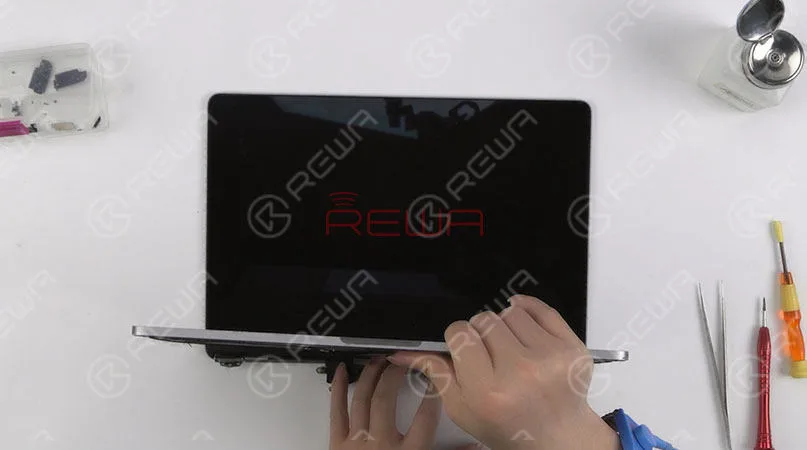
    The MacBook LCD repair is obviously more cost-effective than the replacement of the entire MacBook display assembly. However, single MacBook display replacement can be really difficult. It requires professional skills of technicians. Well, check our video today and you can see how the technician removes the display with just two pieces of Air Slice instead of the use of a Hot Air Gun. Which can greatly reduce the difficulty of MacBook screen replacement. 

  • MacBook LCD Repair: Easy Fix with Air Slice Tool

    MacBook LCD Repair: Easy Fix with Air Slice Tool

    So you have your MacBook screen damaged.

    What’s next? We can find repair guides on MacBook display replacement on different repair websites.

    As our previous blog: 5 Minutes Done – MacBook No Display Repair.

    The weird thing is that it is so popular for technicians to replace the whole display assembly instead of a single display. Why?

    The replacement of a MacBook display is more cost-effective than the replacement of the entire MacBook display assembly.

    However, here is the problem. Single-display replacement can be really difficult and it requires the professional skills of technicians.

    Well, that’s what our blog today is talking about.

    Follow our repair guide and you can see how the technician removes the display with just two pieces of Air Slice instead of the use of a Hot Air Gun.

    Which can greatly reduce the difficulty of screen replacement?

    Hope we will enlighten you somehow about MacBook single display replacement.

    Step 1 Fault Finding

    Press the power button.

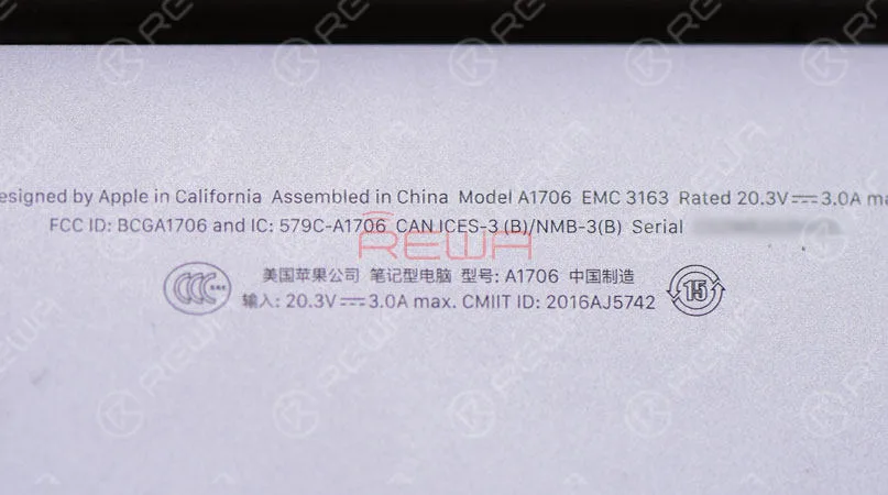
    Confirm the model and year of release on the lower case.

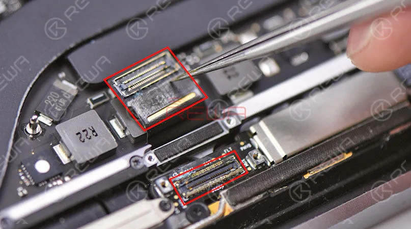
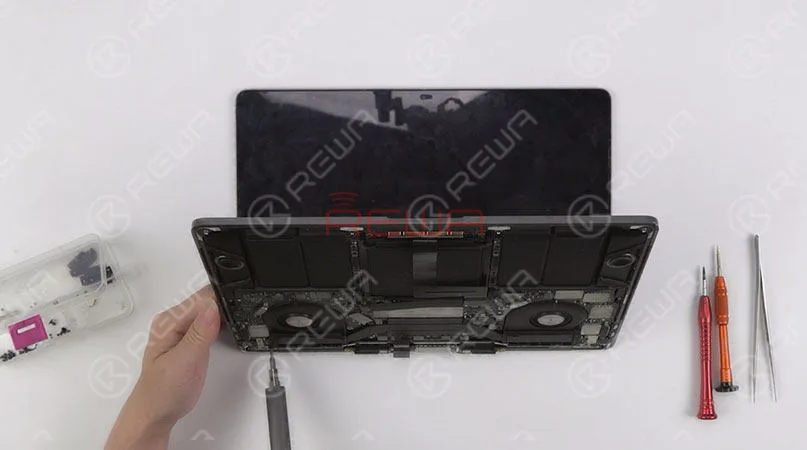
    Then remove the lower case and disconnect the battery. Remove the screws securing the display flex cable and disconnect the display flex cable.

    Press the power button. The MacBook won’t turn on. Confirm the model and year of release on the lower case. Then remove the lower case and disconnect the battery. Remove screws securing the display flex cable and disconnect the display flex cable.

    We can see that the display flex cable and the display connector have been water-damaged with corrosion.

    So we need to replace it with a new display flex cable and a new display.

    We can see that the display flex cable and the display connector have been water damaged with corrosion. So we need to replace with a new display flex cable and a new display.

    Step 2 Display Flex Cable Replacing

    Remove the screws securing the logic board and take out the logic board.

    Remove the screws securing the display flex cable and replace it with a new display flex cable.

    Once done, tighten the screws securing the display flex cable.

    Get the logic board installed and secured with screws.

    Remove screws securing the logic board and take out the logic board. Remove screws securing the display flex cable and replace with a new display flex cable. Once done, tighten screws securing the display flex cable. Get the logic board installed and secured with screws.

    Step 3 Screen Separating

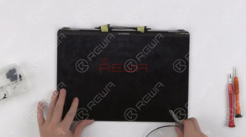
    Continue to remove the screws securing the screen.

    Then separate the display assembly from the bottom half keyboard.

    Continue to remove screws securing the screen. Then separate the display assembly from the bottom half keyboard.

    Step 4 Screen Replacing

    Now, let’s move on to display replacement.

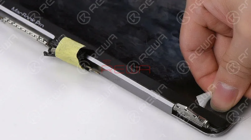
    First, secure the backlight flex cable with a sticker.

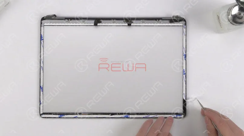
    Then remove the rubber gasket around the edges of the screen.

    Now, let’s move on to display replacement. First, secure the backlight flex cable with sticker. Then remove the rubber gasket around edges of the screen.

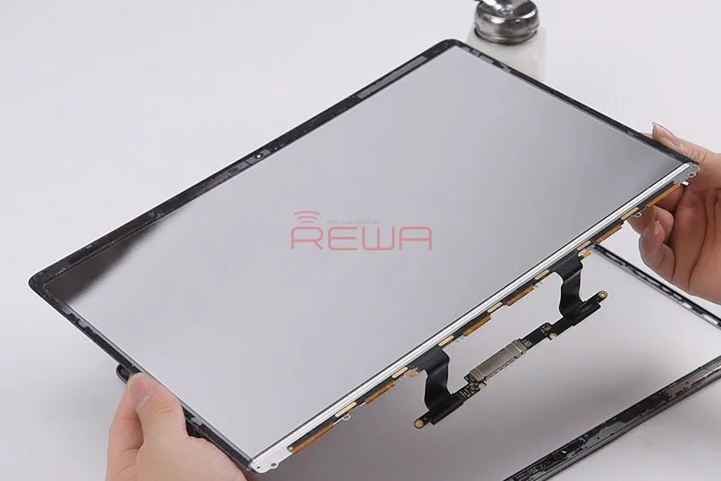
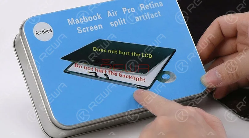
    Here we will use a special MacBook screen separating tool – Air Slice to detach the display from the upper case.

    Here we will use a special MacBook screen separating tool - Air Slice to detach the display from the upper case.

    8 pieces of screen separating slice in 4 specifications 10 pieces of LOGO removing slice in the plastic box Take out a piece of LOGO removing slice.

    Dip some alcohol and then insert the slice under the LOGO strip.

    Slip back and forth to detach the LOGO strip.

    Continue to remove the screws securing the screen iron bar.

    Remove the spring bar afterward.

    8 pieces of screen separating slice in 4 specifications 10 pieces of LOGO removing slice in the plastic box Take out a piece of LOGO removing slice. Dip some alcohol and then insert the slice under the LOGO strip. Slip back and forth to detach the LOGO strip. Continue to remove screws securing the screen iron bar. Remove the spring bar afterwards.

    Take out a piece of screen separating a slice of 0.05.

    Dip some alcohol first.

    Then insert the slice from the right bottom corner of the screen.

    Make sure the slice has been inserted under the screen iron bar.

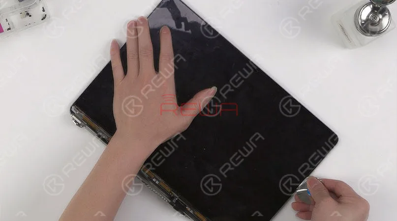
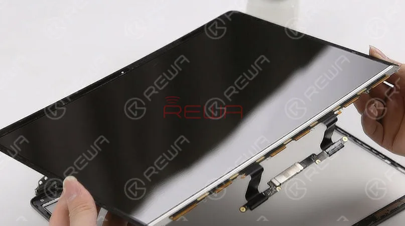
    Slip the screen separating the slice back and forth to detach the display from the upper case.

    Take out a piece of screen separating slice of 0.05. Dip some alcohol first. Then insert the slice from the right bottom corner of the screen. Make sure the slice has been inserted under the screen iron bar. Slip the screen separating slice back and forth to detach the display from the upper case.

    We can see that the display has not been damaged during the process.

    We can see that the display has not been damaged during the process.

    Dip some alcohol with the screen separating the slice and then remove the iron bar securing the screen. Prepare a new A1706 display.

    Remove double-sided tape residue on the iron bar of the original screen first.

    Then stick new double-sided tape on the iron bar.

    Adhere the iron bar onto the new display.

    Then adhere the display flex cable onto the iron bar.

    Get the rubber gasket around the edges of the screen set up.

    Dip some alcohol with the screen separating slice and then remove the iron bar securing the screen. Prepare a new A1706 display. Remove double-sided tape residue on the iron bar of the original screen first. Then stick new double-sided tape on the iron bar. Adhere the iron bar onto the new display. Then adhere the display flex cable onto the iron bar. Get the rubber gasket around edges of the screen set up.

    Stick double-sided tape on three sides of the upper case.

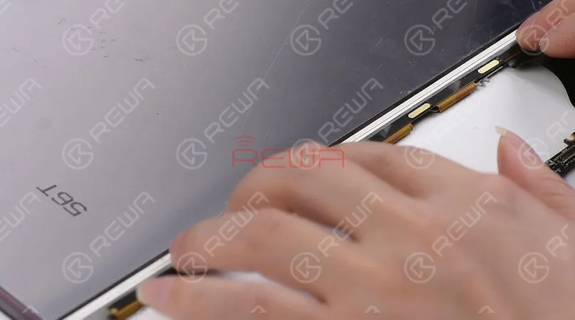
    First, tear open the tape at the end and then remove dirty spots on the backlight paper.

    Tear off the protective film on the screen.

    Get the new display in position.

    Apply pressure to fit the display with the upper case.

    Meantime, tear off the protective layer of the double-sided tape.

    Make sure the display and the upper case fit perfectly.

    Stick double-sided tape on three sides of the upper case. First, tear open the tape at the end and then remove dirty spots on the backlight paper. Tear off the protective film on the screen. Get the new display in position. Apply pressure to fit the display with the upper case. Meantime, tear off the protective layer of the double-sided tape. Make sure the display and the upper case fit perfectly.

    Step 4 Installation & Test

    Once done, get the spring bar installed.

    Tighten the screws securing the screen iron bar and then get the LOGO strip adhered.

    Get the display assembly and the bottom half keyboard assembled.

    Continue to get the WiFi antenna installed and the display flex cable secured.

    Tighten the screws securing the WiFi antenna and the screen.

    Once finished, connect the battery and get the lowercase installed.

    Once done, get the spring bar installed. Tighten screws securing the screen iron bar and then get the LOGO strip adhered. Get the display assembly and the bottom half keyboard assembled together. Continue to get the WiFi antenna installed and the display flex cable secured. Tighten screws securing the WiFi antenna and the screen. Once finished, connect the battery and get the lower case installed.

    In the end, plug in the AC adapter and power it on.

    The MacBook turns on normally. The keyboard and the trackpad also work normally.

    In the end, plug in the AC adapter and power on. The MacBook turns on normally. Keyboard and the trackpad also work normally.

    For a visualized understanding of MacBook single display replacement, please follow the video below.

    As for more repair videos, just subscribe to our YouTube channel here.

    In REWA, everything comes after quality

    We’re listening. Have something to say about this article?

    Share it with us on ASK Forum, FaceBook, LinkedIn, or our FaceBook group.

  • MacBook Air Won’t Turn On – Logic Board Troubleshooting

    MacBook Air Won’t Turn On – Logic Board Troubleshooting

    For repair technicians, their repair work usually goes differently, since the problem can be fixed and solutions may be flexible.

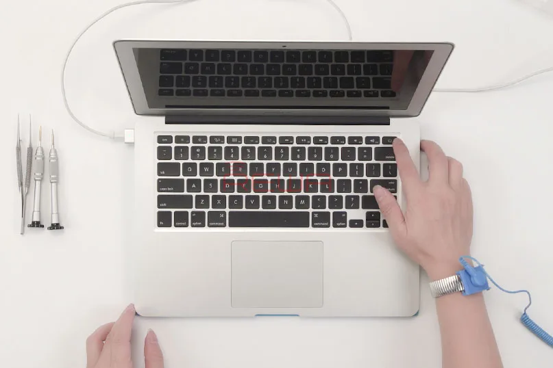
    For our MacBook Air won’t turn on repair case today, in order to demonstrate a complete repair process, we started from main power supply inductor in this video.

    The fault is finally confirmed as to be caused by fuse damage due to short-circuited capacitor on the main power supply circuit.

    Actually, you can find the problem directly based on experience if you are an old hand.

    REWA never lets you down and always has an EFI chip solution for MacBook unlock repair for you.

    Now, following to see how to troubleshoot MacBook won’t power on issue.

    Press power button, the MacBook won’t turn on.

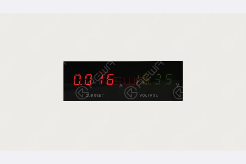
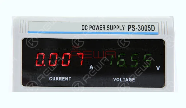
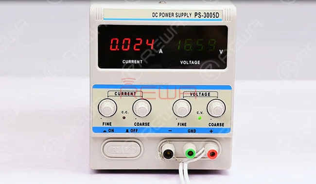
    Then plug in the power source and press power button, it current displays as 0.013A-0.016A. which indicates that the MacBook features not charging and not turning on issue.

    MacBook Air Won't Turn On

    First, confirm the serial number on the lower case. then remove the lower case and disconnect the battery.

    Next, detach the logic board and I/O Board from the enclosure, and connect the I/O Board to the logic board.

    Remove the SSD and WiFi module, confirm the board number of the logic board.

    Check the DDR RAM and CPU frequency from the label, roll out the circuit diagram and bitmap.

    Locate L7130 of PPBUS_G3H on the bitmap.

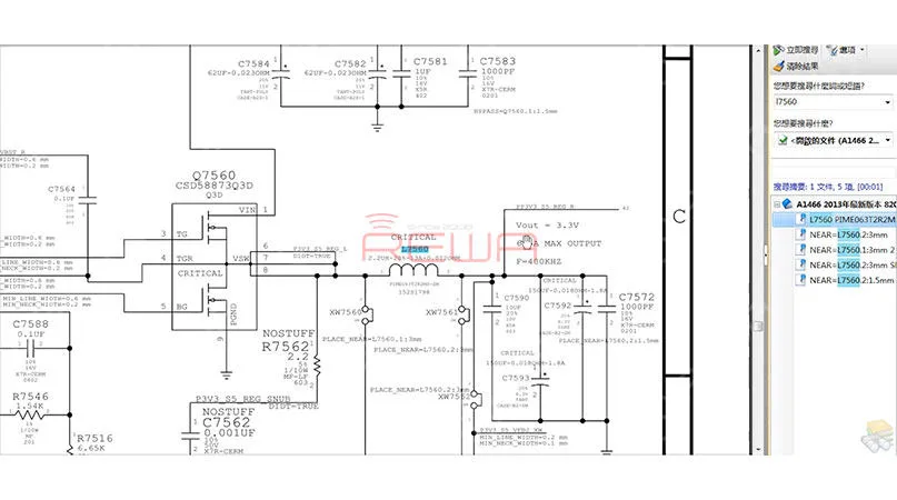
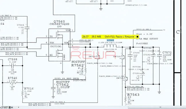
    Then run voltage measurement of L7130, the measured value is 8.5V, which is normal. continue to locate L7560 of PP3V3_S5_REG on the bitmap, run voltage measurement of L7560, the measured value is 0.637V, which is abnormal. (The normal value should be around 3.3V)MacBook Air Won't Turn On

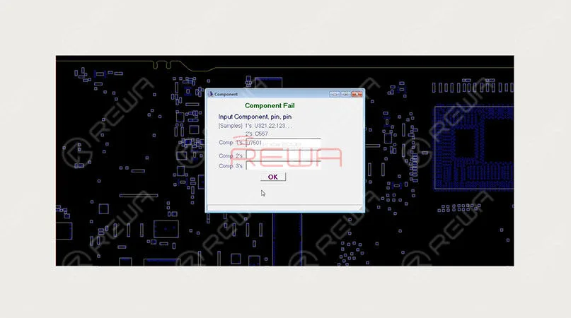
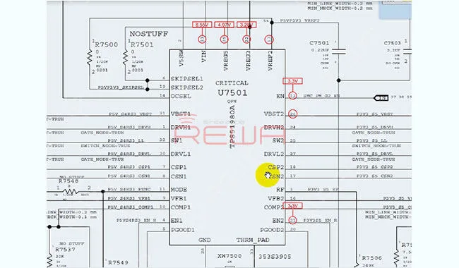
    According to the circuit diagram, Voltage of PP3V3_S5_REG is outputted by U7501 DC-DC power converter.

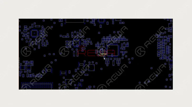
    Locate the exact position of U7501 on the board with bitmap.

    Then check the working condition of U7501 with the circuit diagram.

    MacBook Air Won't Turn On

    First, check whether the input voltage of Pin VIN on U7501 is normal. (Locate the exact position of C7500 on the board with bitmap and confirm it by running voltage measurement of Pin 1.)

    The measured value is 0.878V, which is abnormal. (The normal value should be around 8.5V)

    MacBook Air Won't Turn On

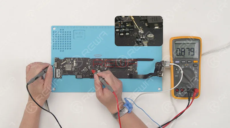
    PPBUS_S5_HS_OTHER_ISNS, the rail-related to Pin VIN of U7501 is converted from PPBUS_G3 H with the help of R5430. Locate the exact position of R5430 on the board with bitmap, the run voltage measurement of Pin 2 on R5430, the measured value is 0.879V, which is abnormal. PPBUS_G3H is fulfilled with the help of L7130 by way of F7140.

    Continue to run diode mode measurement of Pin 1 and Pin 2 on F7140, the measured value of Pin 1 is 131, which is normal; the measured value of Pin 2 is 2, which is abnormal.

    Judging by this, the loading of PPBUS_G3H is short for grounding.

    MacBook Air Won't Turn On

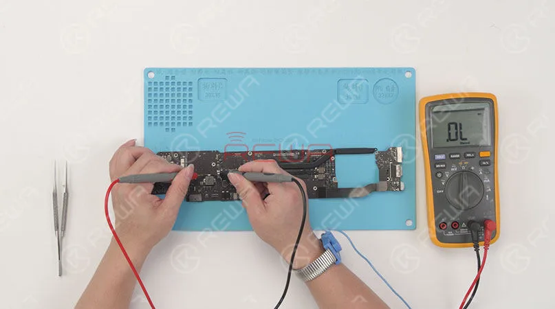
    Run diode mode measurement of F7140, it reads ‘OL’ on the Multimeter, which is infinite value. Judging by this, F7140 has been burnt out.

    MacBook Air Won't Turn On

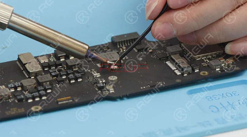
    Solder the supply wire to Pin 2 of F7140, then supply a 2V voltage with an external power source.

    Current reading on the ammeter rises to 2.622A.

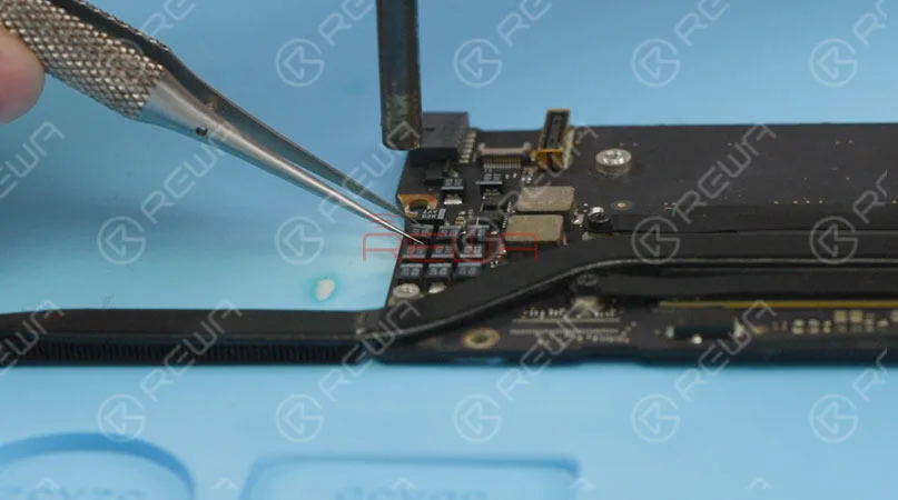
    And touch the logic board with one hand, capacitor C7371 next to the CPU is hot. So the fault might be related to C7371.

    MacBook Air Won't Turn On

    Disconnect the power supply, replace C7371 and F7140 with a new one in turn.

    Run diode mode measurement of F7140, it reads ‘0’ on the Multimeter, which is normal.

    Wait for the logic board to cool for several minutes, then connect the I/O Board to the logic board.

    Plug in the power source, current reading on the ammeter is normal this time.

    MacBook Air Won't Turn On
    MacBook Air Won't Turn On

    Run voltage measurement of Pin 2 on F7140, the measured value is 8.5V, which is normal.

    Continue to run voltage measurement of L7560,

    The measured value is 3.3V, which also is normal.

    Disconnect the power supply and get the logic board installed, plug in the power source and press Option key. the screen displays normally, and the touch panel also works normally.

    Next, let’s assemble the MacBook and test.

    Press the power button, then the Option key, the screen displays normally.

    The MacBook turns on and accesses the system normally, the Keyboard also works normally.

    Plug in the power source, the MacBook is charging normally.

    Repair completed successfully.

    Now, check our video for more detail about MacBook Air Won’t Power On

    Attaching the list of the tools used in the video. Welcome customers in need of inquiries. We will help you with whatever you need.

    • *Hot Air Gun Rework Station
    • *Soldering Iron Rework Station
    • *Digital Multimeter
    • *DC Regulated Power Supply
    • *Straight Tweezer
    • *Paste Flux
    • *Solder Wire
    • *Anti-static Plastic Pry Bar
    • *Soft Brush
  • Unlock MacBook 2015-2017 Without Chip Removal

    Unlock MacBook 2015-2017 Without Chip Removal

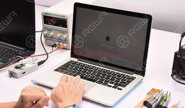
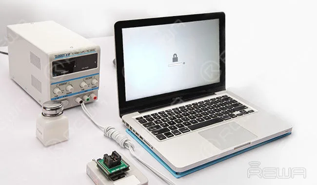
    In previous blog, we have introduced how to unlock MacBook by removing EFI passwords. This time we come with a new method to unlock MacBook 2015-2017. With the help of EFI Chip Free Removal Unlock Tool, you do not need to remove the chips, and the EFI password is cleared with HEX editor. Let’s find out how to make your MacBook repair easier.

    Unlock MacBook 2015-2017 No Chip Removal

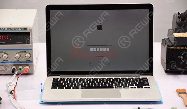
    The MacBook Pro requires PIN to log in. Give the PIN a try and PIN failed.

    Unlock MacBook 2015-2017 No Chip Removal

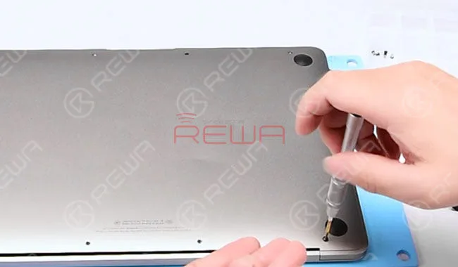
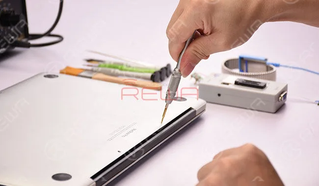
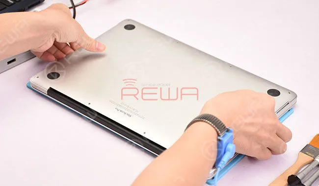
    Power off and remove the lower case. Detach IPG trackpad keyboard flex and the battery.

    Unlock MacBook 2015-2017 No Chip Removal

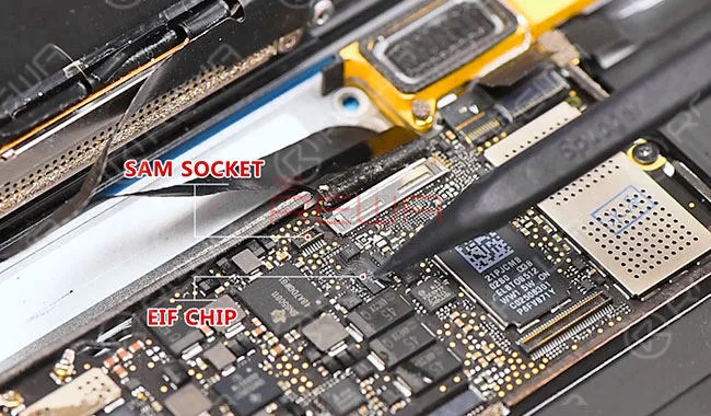
    Locate the SAM Socket and EFI chip. Then confirm the board number of logic board: 820-00045-10.

    Unlock MacBook 2015-2017 No Chip Removal

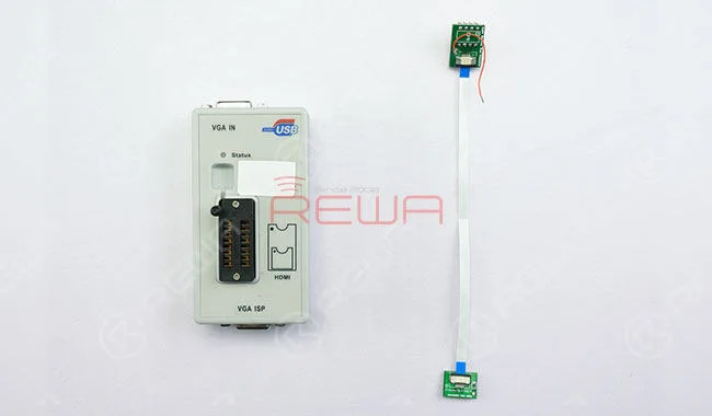
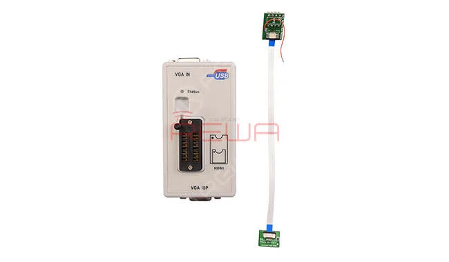
    EFI Chip Free Removal Unlock Tool (12 pins)

    Unlock MacBook 2015-2017 No Chip Removal

    NoteThe unlock tool works with MacBook Pro 2015-2017; MacBook Air 2015-2017; MacBook 2015-2016

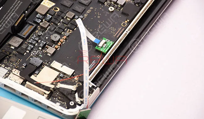
    Locate the power supply pin of EFI chip on the repair drawing and locate the pin 1 of SAM socket on the logic board.

    Unlock MacBook 2015-2017 No Chip Removal

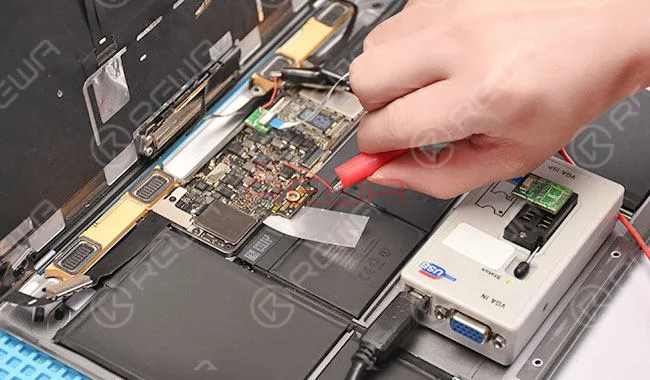
    Buckle the unlock tool correspondingly. Then solder a power supply wire to the power supply pin of EFI chip.

    Unlock MacBook 2015-2017 No Chip Removal

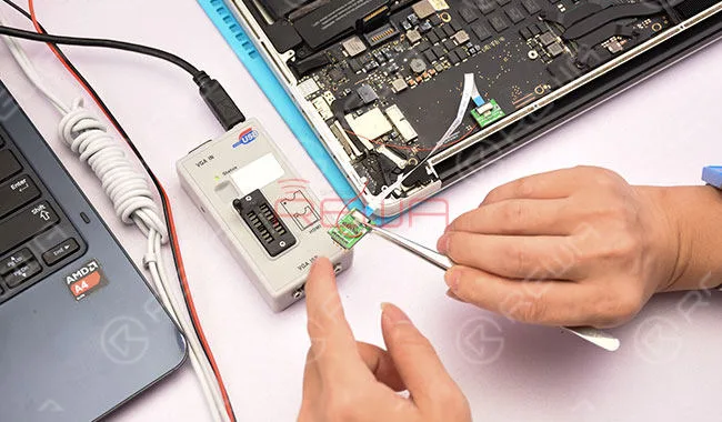
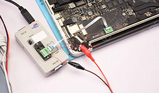
    Connect with the programmer and then supply power to EFI chip at 3.3V from DC Power Supply.

    Unlock MacBook 2015-2017 No Chip Removal

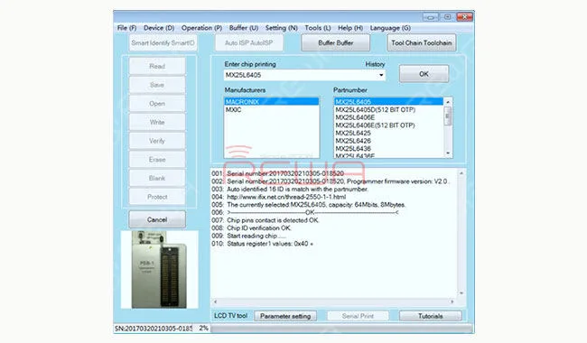
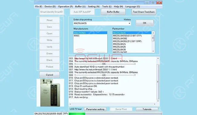
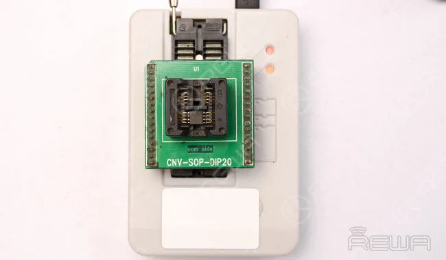
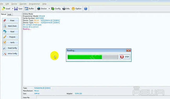
    Connect the unlock tool with the computer and read EFI chip data.

    Unlock MacBook 2015-2017 No Chip Removal

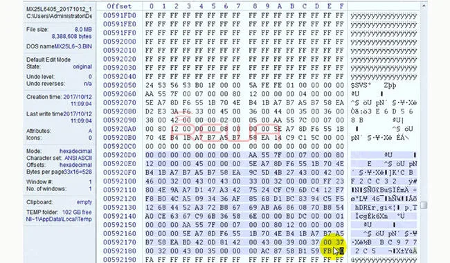
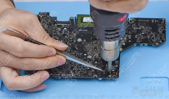
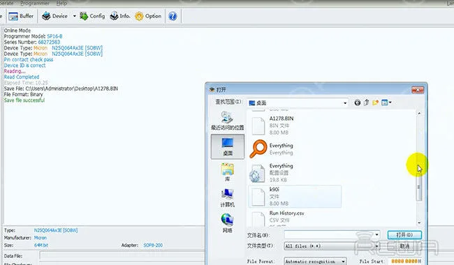
    Save as a bin file. Then edit the bin file in HEX editor. Locate the specific field. Replace characters in the field to clear password. Once done, save the bin file.

    Unlock MacBook 2015-2017 No Chip Removal

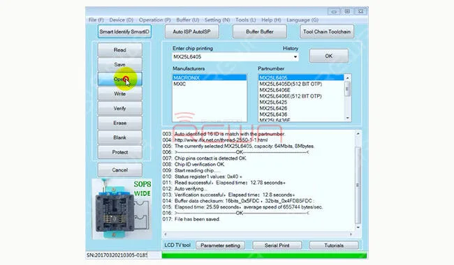
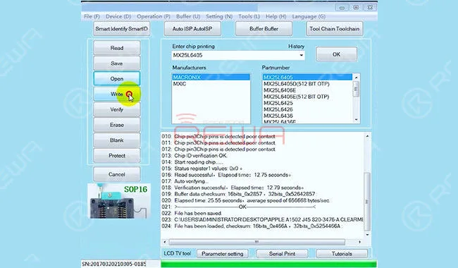
    Open the free password bin file and “Write”. Only the original EFI data works with the clearance of data password.

    Unlock MacBook 2015-2017 No Chip Removal

    Once finished, detach the unlock tool and power supply wire. Then buckle the battery and get the lower case assembled.

    Unlock MacBook 2015-2017 No Chip Removal

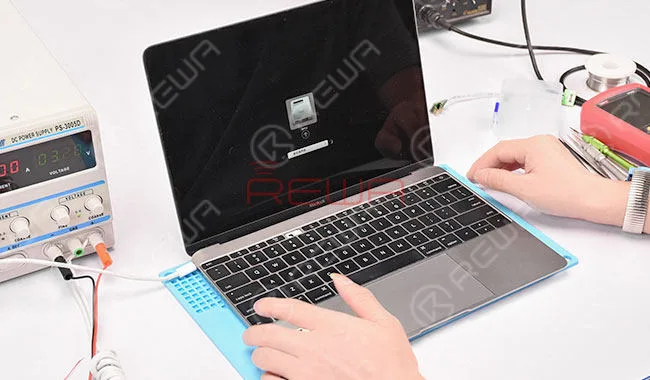
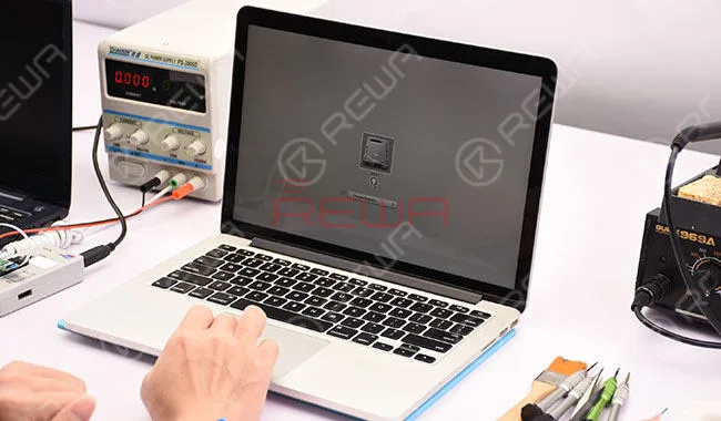
    Plug in MacBook AC Adapter and press “Option Key+Power Button” to power up. There is no firmware lock on the interface.

    Unlock MacBook 2015-2017 No Chip Removal

    Yet the PIN lock still exists. Power off and then press “Option+Command+R+P+Power Button” to erase NVRAM and power up.

    Unlock MacBook 2015-2017 No Chip Removal

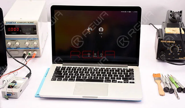
    MacBook unlocked successfully.All data remain the same after unlocking, no need for OS reinstallation

    For more details on Unlock MacBook 2015-2017 Repair guide, please go to REWA YouTube channel.

    Necessary Parts And Tools

  • MacBook Air Won’t Turn On Troubleshooting

    MacBook Air Won’t Turn On Troubleshooting

    MacBook Air won’t turn on repair can be seen as one comprehensive fault case with high difficulty. And MacBook Air won’t turn on issue caused by cockroaches? Have you ever come across? Today we will introduce a series of diagnostic and repair techniques regarding MacBook Air A1466 (Mid-2013) won’t turn on the issue. The solution covers both fault diagnosis by measurement of voltage, current and resistance, and the replacing of resistor, inductor and IC. Surely you will get surprised.

    macbook air won turn troubleshooting

    Necessary Parts And Tools

    Parts And Tools

    MacBook Air Won’t Turn On Troubleshooting

    Phenomenon

    Plug in AC adapter, the power light won’t turn on.

    MacBook Air Won't Turn On Troubleshooting

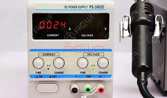
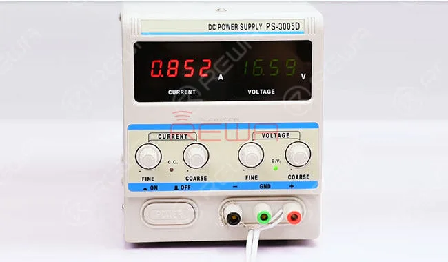
    The DC Power Supply also displays abnormal standby current. Normal current should be 0.8A.

    MacBook Air Won't Turn On Troubleshooting

    Disassembling

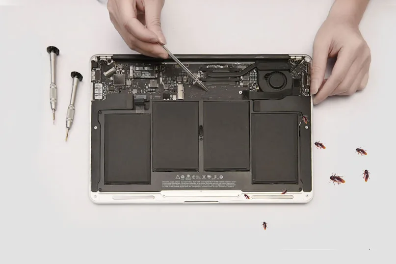
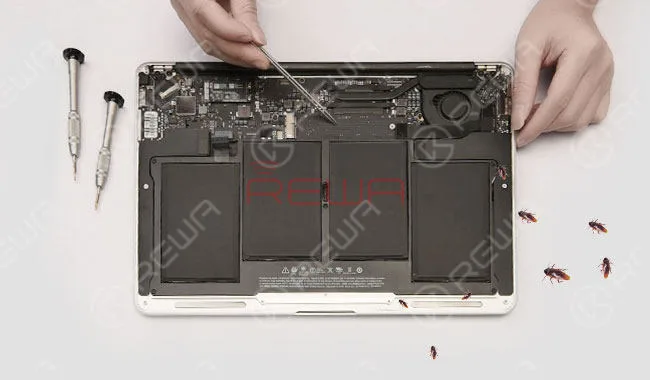
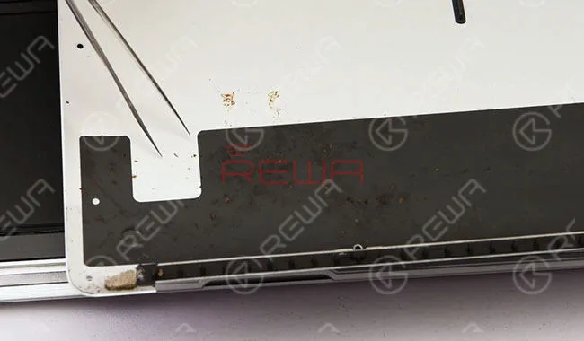
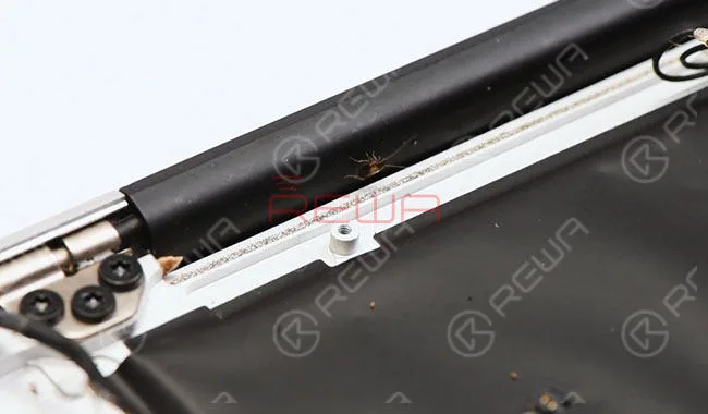
    Disassemble the Mac and Remove the lower case. Traces of cockroaches all around (which caused corrosion).

    MacBook Air Won't Turn On Troubleshooting

    Disconnect the battery and Remove the SSD module. Confirm the number of logic board, 820-3437-B. Detach the logic board. Active cockroaches can also be seen on the logic board (which caused corrosion).

    MacBook Air Won't Turn On Troubleshooting

    Warm tips: clean the logic board thoroughly after completion of repairing

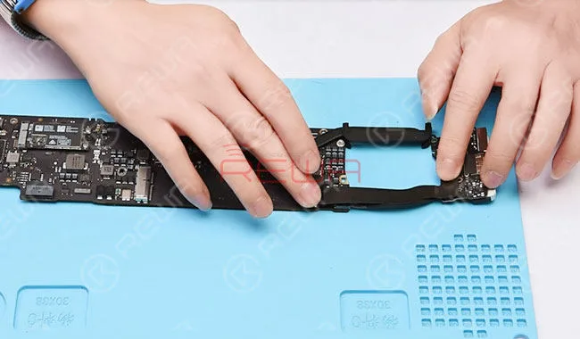
    Detach IO Board as well and then attach it to the logic board.

    MacBook Air Won't Turn On Troubleshooting

    Diagnosing And Repairing

    Phase 1

    Get the Multimeter Prepared at resistance mode. Measure the resistance value of logic board power supply inductors. The value is normal.

    MacBook Air Won't Turn On Troubleshooting

    Switch to voltage mode. Plug in AC adapter and measure the voltage value of standby circuit inductor. The voltage value is way lower than normal.

    MacBook Air Won't Turn On Troubleshooting

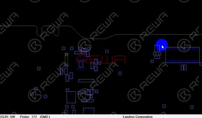
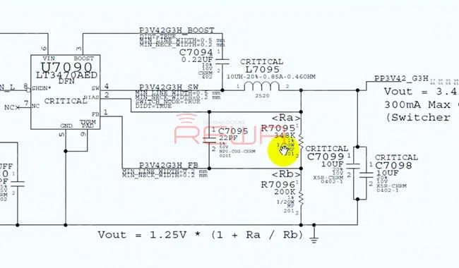
    Locate the inductor withdrawing and bitmap and confirm the circuit diagram of L7095.

    MacBook Air Won't Turn On Troubleshooting
    MacBook Air Won't Turn On Troubleshooting

    Measure the voltage value of IC working condition. The working condition is normal.

    MacBook Air Won't Turn On Troubleshooting

    Switch to resistance mode and measure the feedback resistance value of IC. The output working condition of inductors should be Vout=1.25V*(1+Ra/Rb). The resistance value is way larger than normal.

    MacBook Air Won't Turn On Troubleshooting

    So we need to replace with new resistors.

    Detach new resistors from the spare plate and solder them to the target board. Then measure the resistance value of resistors replaced. The resistance value of R7095 is 200KΩ, R7096 160KΩ. Which is normal.

    MacBook Air Won't Turn On Troubleshooting

    Plug in AC adapter. The power light turns on this time.

    MacBook Air Won't Turn On Troubleshooting

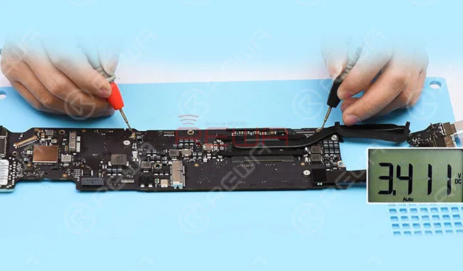
    Measure the voltage value of inductor L7095, 3.41V. Normal voltage value.

    MacBook Air Won't Turn On Troubleshooting

    Check the current of DC Power Supply. The current is abnormal. Which indicates that the MacBook still cannot be powered up.

    MacBook Air Won't Turn On Troubleshooting

    Phase 2

    Measure the voltage value of power supply inductor. The voltage value is erratic.

    MacBook Air Won't Turn On Troubleshooting

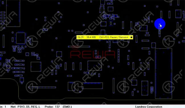
    Locate the inductor withdrawing and bitmap and confirm the power supply circuit of L7560. 

    MacBook Air Won't Turn On Troubleshooting
    MacBook Air Won't Turn On Troubleshooting

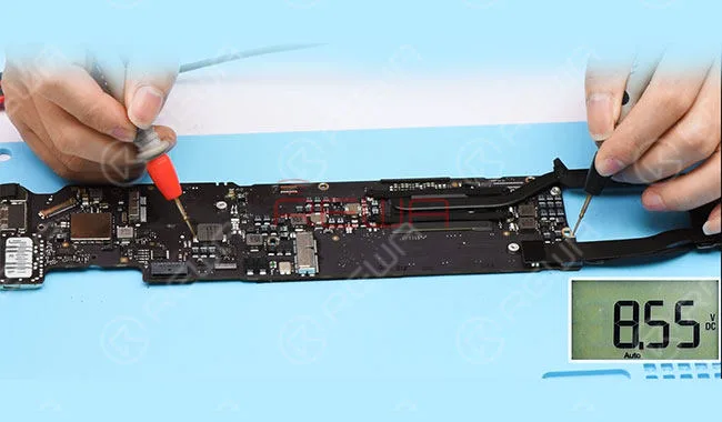
    Measure the voltage value of IC working condition. Pin 23, 8.55V. Pin 29, 4.97V. Pin 22, 3.28V. Pin 21, 3.3V. Pin12, 3.3V. The voltage value of pin 13 and pin 26 is erratic.

    MacBook Air Won't Turn On Troubleshooting

    We have a suspicion that the power supply IC broke down.

    So we need to replace with a new power supply IC.

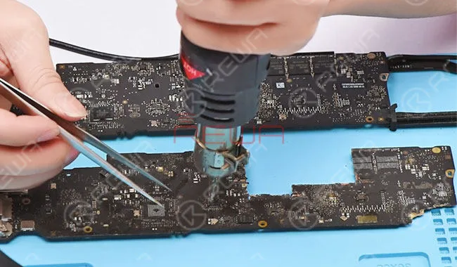
    Detach a new power supply IC from the spare plate and solder the power supply IC to the target board. Clean the logic board after cooling.

    MacBook Air Won't Turn On Troubleshooting

    Plug in AC adapter and check the current. The current is just the same as before (with the original power supply IC). The fault hasn’t been cleared.

    MacBook Air Won't Turn On Troubleshooting

    Phase 3

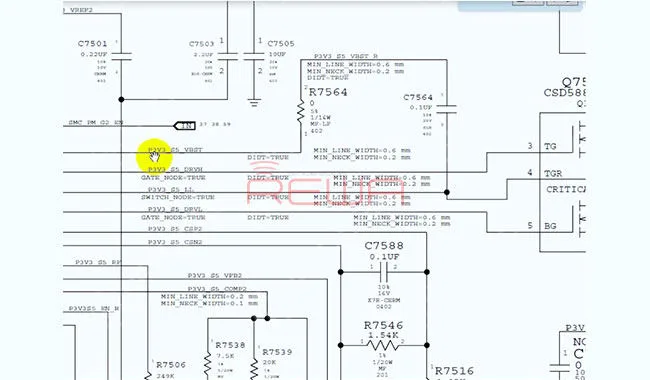
    Measure the voltage value of logic board again. The voltage value of Pin 26 is erratic. So we need to confirm the power supply circuit of pin 26. Roll out the maintenance drawing and bitmap and Locate R7564.

    MacBook Air Won't Turn On Troubleshooting

    Disconnect AC adapter and switch to resistance mode. The measured resistance value of R7564 is 1MΩ. Which is abnormal.

    MacBook Air Won't Turn On Troubleshooting

    So we need to replace with a new resistor.

    Detach a new resistor from the spare plate and solder it to the target board. Clean the logic board after cooling.

    MacBook Air Won't Turn On Troubleshooting

    Measure the resistance value of R7564 again. The measured resistance value of R7564 is 0.5MΩ. Which is normal. Plug in AC adapter and check the current. Normal current this time.

    MacBook Air Won't Turn On Troubleshooting

    Measure the voltage value of resistor R7564. Normal voltage value.

    Testing

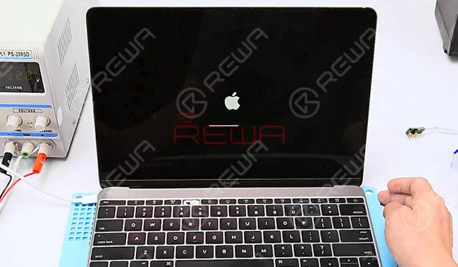
    Get the logic board mounted and turn on the MacBook. The MacBook powered up with a normal display.

    MacBook Air Won't Turn On Troubleshooting

    Assemble the MacBook and test. The fault has been cleared.

    MacBook Air Won't Turn On Troubleshooting

    We can finish the MacBook Air won’t turn on repairing work by getting the MacBook full assembled. And do you want to MacBook air ram upgrade, you can read this post.

    MacBook Air Won't Turn On Troubleshooting

    For more details on MacBook Air won’t turn on troubleshooting, please go to REWA YouTube channel.

    Tools Used, for more repair tools please go to shop.rewa.tech to get.

  • How To Unlock MacBook By Removing EFI Password?

    How To Unlock MacBook By Removing EFI Password?

    Our previous EFI Chip Solution For MacBook Unlock Repair has introduced an EFI chip solution regarding the unlock MacBook issue. We have made a guide: how to bypass icloud lock on iPhone 6 no later, however, if you are not good at micro soldering, never mind, this time REWA come up with a new unlock method with EFI password removing regarding the unlock MacBook issue. Check it out by yourself now!

    How To Unlock MacBook By Removing EFI Password

    Unlock MacBook By Removing EFI Password

    The MacBook Pro requires a PIN to log in. As the MacBook powered up with Option key, Another LOCK appears. Both the two locks were not configured by users.

    How To Unlock MacBook By Removing EFI Password

    Remove the lower case and detach the battery. Remove the SSD and then confirm the board number of logic board: 820-3476-A so that we can match with the specific firmware.

    How To Unlock MacBook By Removing EFI Password

    EFI Chip Free Removal Unlock Tool (30 pins)

    How To Unlock MacBook By Removing EFI Password

    Locate the power supply pin of EFI chip. Solder the power supply wire.

    How To Unlock MacBook By Removing EFI Password

    Locate the pin 1 of SAM socket on the logic board. Then, buckle the unlock tool correspondingly.

    How To Unlock MacBook By Removing EFI Password

    Connect with the programmer and then supply power to EFI chip at 3.3V from DC Power Supply.

    How To Unlock MacBook By Removing EFI Password

    Connect the unlock tool with PC. The program starts to identify the chip model automatically. Read and save a copy of the original firmware first.

    How To Unlock MacBook By Removing EFI Password

    After that, load a specific firmware. Erase raw data, and write the specific firmware.

    How To Unlock MacBook By Removing EFI Password

    Once finished, detach the unlock tool and power supply wire. Install the SSD and buckle the battery. Get the lower case assembled.

    How To Unlock MacBook By Removing EFI Password

    Press “Option Key”. There is no firmware lock on the interface.

    How To Unlock MacBook By Removing EFI Password

    Press “Option+Command+R+P+Power Button”, erase NVRAM and power up. User login interface appears this time.

    How To Unlock MacBook By Removing EFI Password

    MacBook unlocked successfully. Since all data remain the same after unlocking, there is no need for OS reinstallation.

    Notice

    The unlock tool works with MacBook Pro 2012-2014;

    MacBook Air 2010-2014;

    REWA LAB works with 2014 MacBook Pro unlocking this time;

    All data remain the same after unlocking;

    EFI Chip non – removal solution (with a matching set of Free Removal Unlock Tool).

    For more details on Macbook Unlock Repair guide, please go to REWA YouTube channel.

    Necessary Parts and Tools

  • Expert Chip Level MacBook Logic Board Repair Service

    Expert Chip Level MacBook Logic Board Repair Service

    You have come up with tough MacBook Repairs and don’t know where to get technical support?

    Come to REWA for help.

    With Our network of repair services positioned to offer efficient logic board repair and cracked screen repair services for iPhone and iPad, we are proud to bring MacBook series into the business scope.

    For more details about MacBook logic board repair service, take a closer look at yourself now!

    Chip Level MacBook Logic Board Repair Service

    MacBook Logic Board Repair Service Includes

    Chip Level MacBook Logic Board Repair Service

    Quoted Price With Repair Materials Included

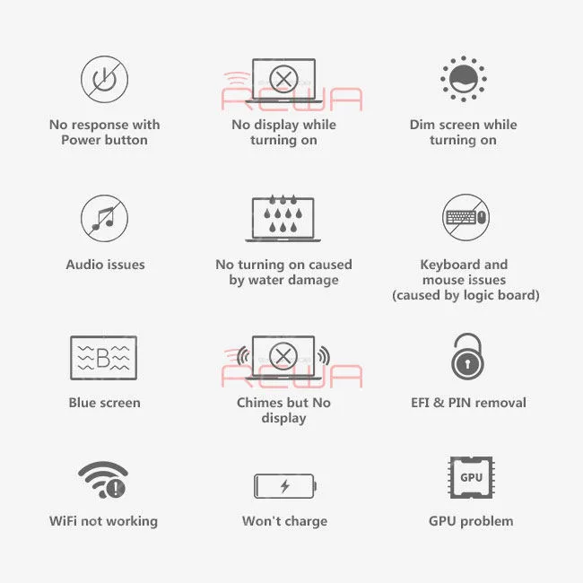
    • 1. No response with the power button
    • 2. No display while turning on
    • 3. Dim screen while turning on
    • 4. Audio issues
    • 5. No turning on caused by water damage
    • 6. Keyboard and mouse issues (caused by logic board)
    • 7. Blue screen
    • 8. Chimes but no display
    • 9. EFI & PIN Removal
    • 10. WiFi not working
    • 11. Won’t charge

    Quoted Price Without Repair Materials Included

    1. GPU issue – the price of the GPU should be borne by the client

    2. LCD /Touch Panel /Keyboard /A Case /B Case /C Case /D Case replacing- the price of these MacBook parts should be borne by the client

    MacBook Logic Board Repair Cases Not Covered by Our Repair Services

    Case 1

    Serious corrosion of extensive components caused by logic board water damage

    Case 2

    Physical form damages, for example, the logic board is bent, deformed or fractured by external force

    How REWA MacBook Logic Board Repair Service Works

    Inquiry

    – Contact our sales and describe the problems to get the preliminary quoted price

    – We will assist you on logic board test, package and logistics

    Delivery

    – State the problems of each board before sending out your logic board

    – Please send REWA sales your e-packing list, picture of package and tracking number

    Payment

    – We will send PI to you and get started with repair once payment is completed

    Logistics

    – Once a repair is finished, we will send back your package

    After-sale Service

    All repair service is covered by a 3-month warranty.

    If the same problem re-occurs within 3 months of the original repair, we will replace the faulty part.

    For some individual cases, we will negotiate with you immediately.

    The warranty does not cover the following situations:

    • 1. A problem caused by software(jailbreak) and virus after the repairing.
    • 2. Damages due to personal error (improper installing) and environmental changing (high pressure, lighting stroke, water damage and so on).
    • 3. Damage of warranty label and private disassembly of device parts

    Customer Notification

    Here are some details we would like you to know before delivery

    • 1. MOQ: 3PCS
    • 2. The repair process(not including delivery time) typically takes about 7 days.(3 – 100 PCS) If your logic board has been repaired before, the repair process might be extended; If the quantity of logic board you sent is more than 100 PCS, then you need to negotiate with us about the repair time.
    • 3. Delivery charges back and forth are borne by clients
    • 4. You need to mark the malfunctions of each device and record their IMEI before delivery
    • 5. Please provide the password for locked Macbook
    • 6. If possible, please provide iCloud account and password; For those who can’t provide iCloud account and password, you need to provide “customer statement file” to ensure the legal source of the whole device or logic board
    • 7. The repair price varies according to the damage statues and quantity of the logic board. The final price is based on the actual inspection and maintenance process
    • 8. For those transferred from Hongkong because of Customs clearance, send the logic board separately, or the whole device with battery detached

    REWA Promises

    All the MacBook replacement materials during the maintenance are original materials

    After the fault clearance, each logic board will be detected completely. Some unstable faults will be aged after being repaired.

  • EFI Chip Solution For MacBook Unlock Repair

    EFI Chip Solution For MacBook Unlock Repair

    Recently, REWA has received a batch of MacBook locked by hackers. Users might be confused by the definition of PIN lock and EFI firmware lock. And the way they might have affected the Macbook. With this blog we will share an EFI chip solution regarding to the MacBook unlock issue. please stay tuned for the next two chapters of MacBook unlock.

    EFI Chip Solution For MacBook Unlock Repair

    EFI Chip Solution For MacBook Unlock Repair

    The MacBook Pro requires PIN to login. Give the PIN a try, yet PIN failed.

    EFI Chip Solution For MacBook Unlock Repair

    Power off. Then hold Option Key and power on. Another LOCK appears on the pop up window. We can draw the conclusion that the MacBook has been Locked by Hackers, since both two passwords failed.

    Power off. Then hold Option Key and power on. Another LOCK appears on the pop up window. We can draw the conclusion that the MacBook has been Locked by Hackers, since both two passwords failed.

    Confirm the MacBook SN first.

    Remove the lower case and disconnect the primary battery.

    Remove the lower case and disconnect the primary battery.

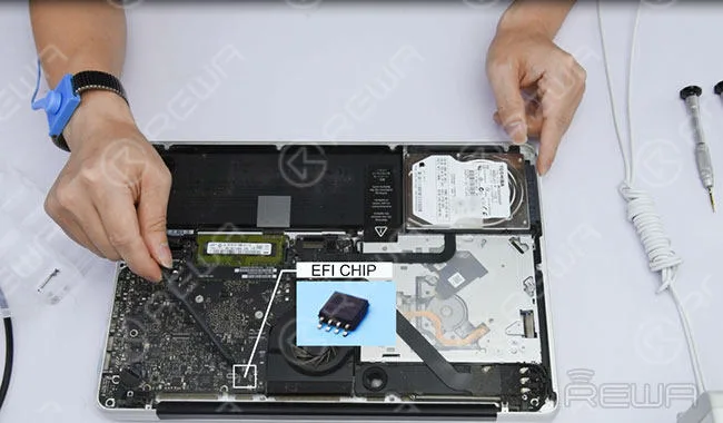
    Locate the EFI chip that stores information. This chip is the key to the unlocking process.

    Locate the EFI chip that stores information. This chip is the key to the unlocking process.

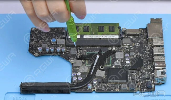
    Then take out the logic board and remove heat sink afterwards. (Logic board is removed from the MacBook to avoid damage to other components during the repairing process.)

    Then take out the logic board and remove heat sink afterwards. (Logic board is removed from the MacBook to avoid damage to other components during the repairing process.)

    Detach the EFI chip from the logic board and then clean the chip.

    Detach the EFI chip from the logic board and then clean the chip.

    Install the chip onto the unlock tool.

    Install the chip onto the unlock tool.

    Connect with the unlock software. Input the chip model number, then Read and backup chip data.

    Connect with the unlock software. Input the chip model number, then Read and backup chip data.

    Load a specific firmware data. Improper firmware may result in unsuccessful unlocking or slow system after successful unlocking.

    Load a specific firmware data. Improper firmware may result in unsuccessful unlocking or slow system after successful unlocking.

    Clear raw data, and write new data. Once finished, take down the EFI chip.

    Clear raw data, and write new data. Once finished, take down the EFI chip.

    Solder the chip to the logic board, then clean with PCB cleaner.

    Solder the chip to the logic board, then clean with PCB cleaner.

    Apply some thermal paste and install heat sink.

    Apply some thermal paste and install heat sink.

    Get the logic board installed.

    Get the logic board installed.

    Press DC Power button to power up.

    Press DC Power button to power up.

    Erase NVRAM and power up (press option+command+R+P+power button). MacBook unlocked successfully. OS X can be re-installed now.

    Erase NVRAM and power up (press option+command+R+P+power button). MacBook unlocked successfully. OS X can be re-installed now.

    Notice:

    Load the specific EFI firmware that matches the MacBook model for unlocking process;

    There are two types of lock for MacBook, PIN and EFI firmware lock;

    Unlock MacBook does not affect the local data;Once locked, if the data hasn’t been erased, then the data remains the same after unlocking;

    Once locked, if the data has been erased, then you need to reinstall the system after unlocking.

    For more details on Macbook unlock Repair guide, please go to REWA YouTube channel.

    You can check out Macbook air ram upgrade guide.

  • MacBook No Display Repair

    MacBook No Display Repair

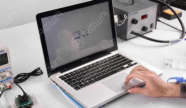
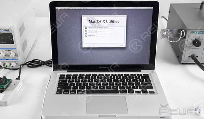
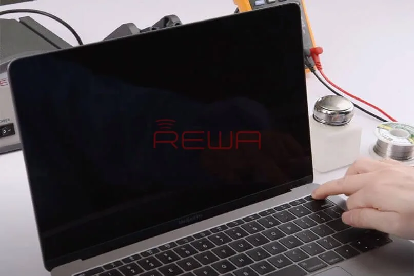
    Recently we noticed some complaints about MacBook air stuck in some peculiar issue during system boot. When your MacBook air is booting to a completely black screen, don’t be panic. REWA here presents you a quick fix for MacBook no display problem with some troubleshooting steps. This solution diagnosed the cause of MacBook black screen step by step and solve the issue by replacing the chip U7701. For more videos related to chip level motherboard repair tutorials, please subscribe our channel.

    Tools Used: 

    • MacBook Spare Parts
    • Multimeter
    • Heat Resistant Insulation Pad
    • Hot Air Gun
    • Soldering Iron
    • BGA Strip Flux Soldering Paste
    • Screwdrivers
    • Plastic Pry Bar
    • Anti-static Wrist Strap