Tag: macbook

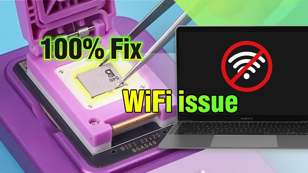
  • MacBook WiFi Won’t Turn On? Professional Guide to Replacing the Wi-Fi Chip on M-Series MacBooks

    MacBook WiFi Won’t Turn On? Professional Guide to Replacing the Wi-Fi Chip on M-Series MacBooks

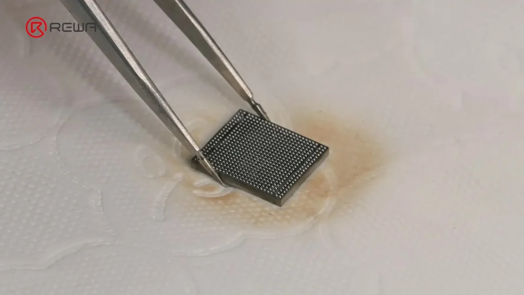
    Apple introduced MacBooks with M-series chips (such as the M1 and M2), which feature a more compact and integrated internal architecture. A key change is the combination of Wi-Fi and Bluetooth functions into a single chip. While this integration enhances performance and efficiency, it presents a significant challenge for repair technicians: when the Wi-Fi chip fails or WiFi won’t turn on, the traditional Apple-authorized solution is to replace the entire motherboard (logic board).

    Fortunately, REWA Tech has developed a new Wi-Fi chip replacement method for MacBooks, enabling repair professionals and advanced DIYers to resolve the issue without replacing the entire board. This guide provides a step-by-step process for diagnosing and replacing a failed Wi-Fi chip on a MacBook Air with an M-series chip, restoring full wireless functionality.

    Why Your MacBook Wi-Fi Won’t Turn On

    When Wi-Fi on a MacBook refuses to enable, possible causes include:

    • Wi-Fi chip failure due to overheating, physical impact, or manufacturing defects.
    • Corruption of Wi-Fi chip firmware.
    • Liquid damage affecting the chip’s surrounding circuits.
    • ECID mismatch when replacing components without proper reprogramming.

    On M-series MacBooks, Wi-Fi and Bluetooth are combined into one chip, meaning if one function fails, both can stop working. This guide focuses on hardware-level Wi-Fi chip replacement.
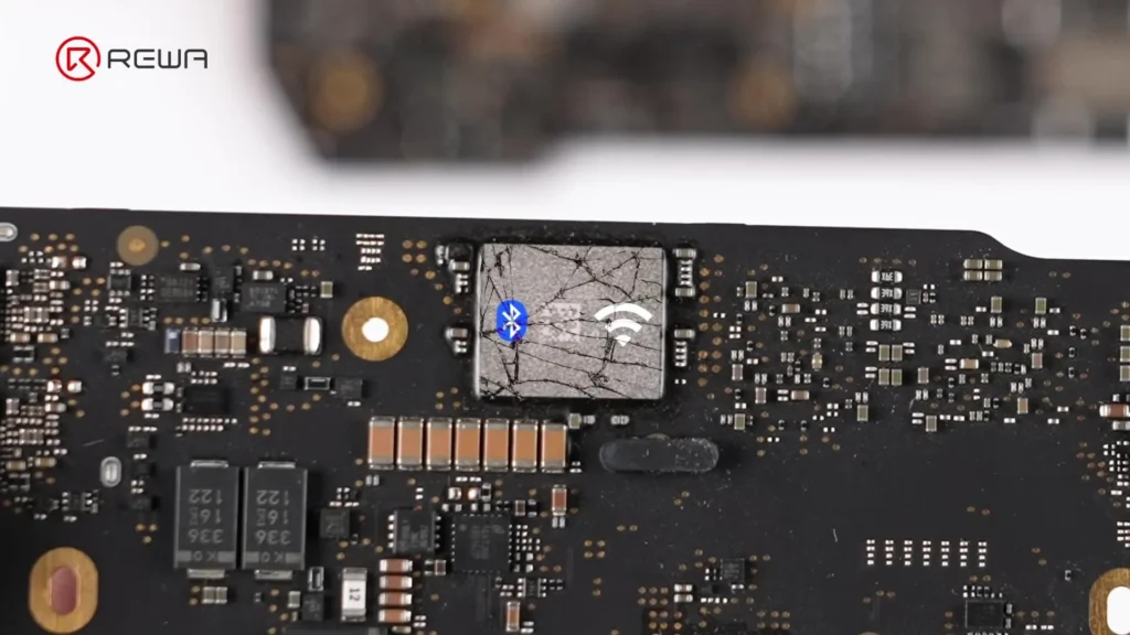
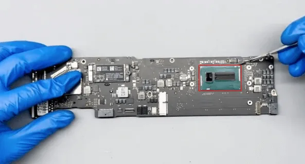
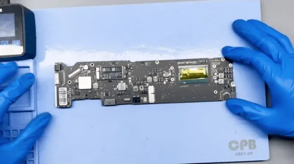
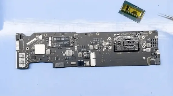
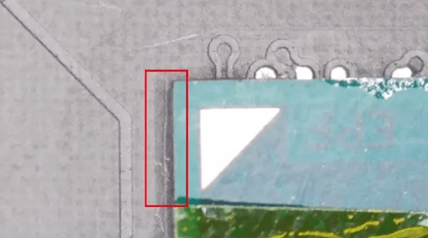
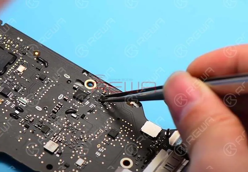
    macbook broken chip

    Step-by-Step Guide: Fixing “MacBook Wi-Fi Won’t Turn On” by Replacing the Wi-Fi Chip

    Step 1: Initial Diagnosis

    1. Confirm that the Wi-Fi option is greyed out or cannot be toggled on in macOS Settings.
    2. Rule out software issues by:
      • Restarting the MacBook.
      • Resetting NVRAM/PRAM (for Intel models; not applicable for M-series).
      • Updating macOS to the latest version.
    3. If Wi-Fi still does not enable, diagnose with repair software or known-good replacement parts to confirm Wi-Fi chip failure.
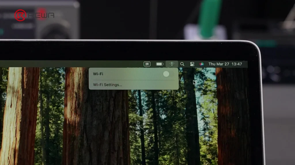
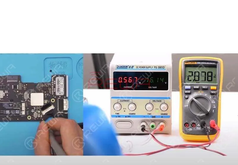
    macbook wifi won't turn on

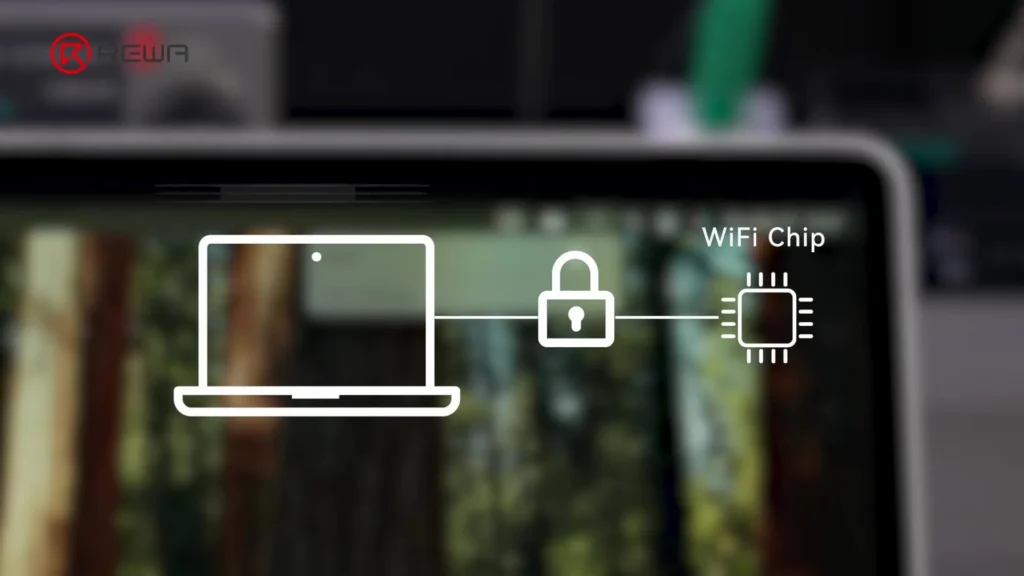
    Step 2: Read the MacBook’s ECID and Unbind the Wi-Fi Chip
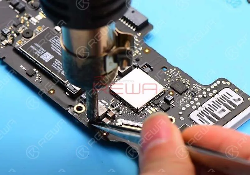
    macbook wifi won't turn on repair

    ECID (Exclusive Chip ID) is a unique serial number tied to the MacBook’s components, including the Wi-Fi chip. To install a replacement chip, you must unbind the old chip from the motherboard.

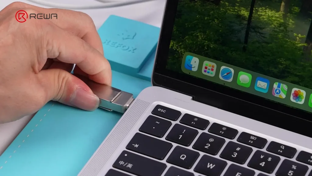
    1. Install LuBan software from a flash drive.
    2. Launch LuBan — it requires internet access.
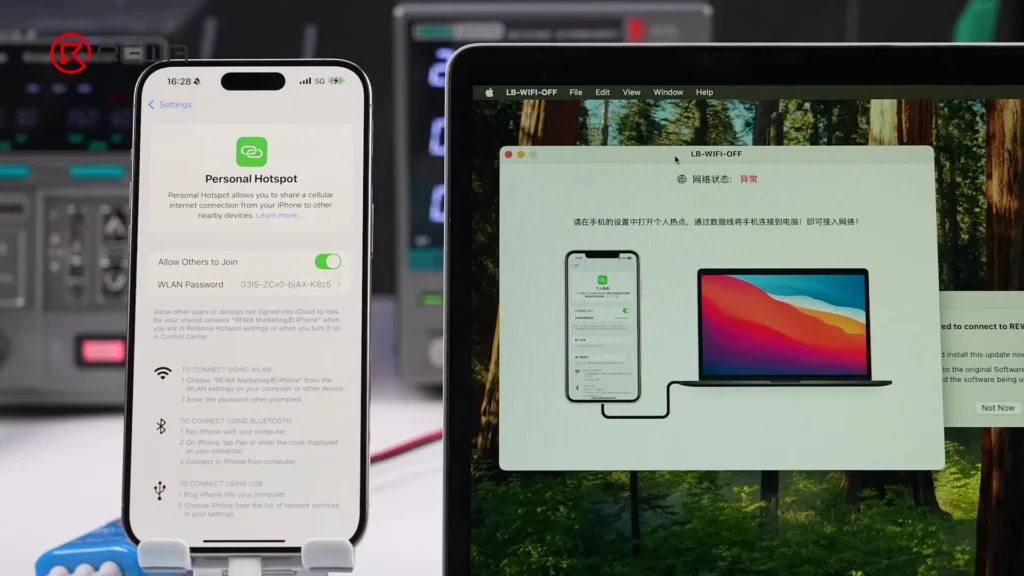
    3. Connect the MacBook to the internet:
      • Use a phone hotspot via USB cable (trust the MacBook on the phone when prompted),
        or
      • Use an Ethernet adapter.
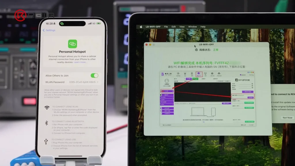
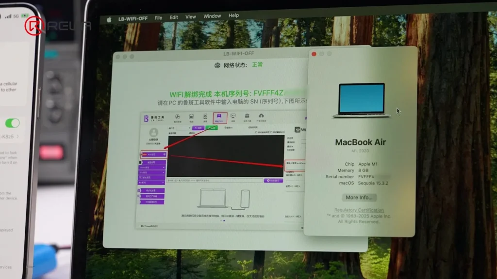
    4. Once connected, LuBan automatically unbinds the existing Wi-Fi chip and reads the ECID.
    5. Verify the ECID in macOS Settings to ensure it matches.
    Step 3: Disassemble the MacBook

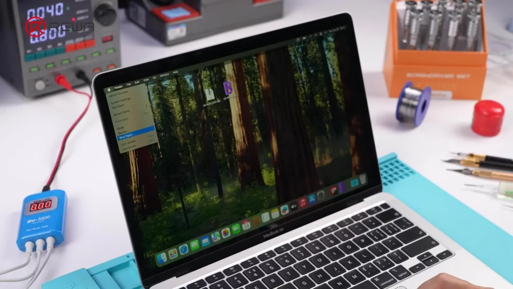
    1. Power off the MacBook.
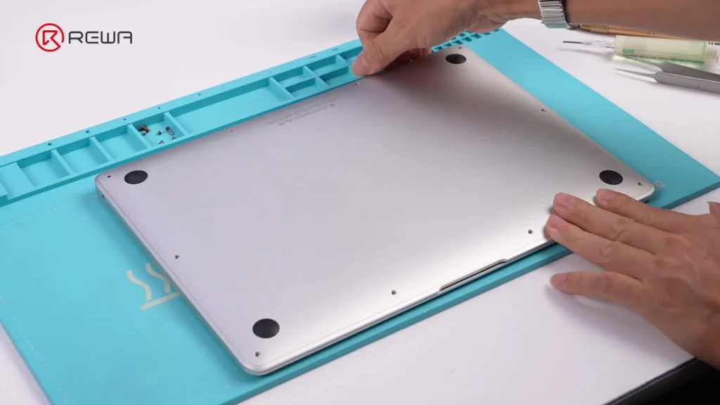
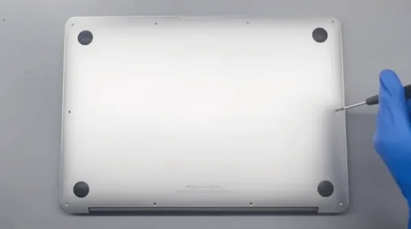
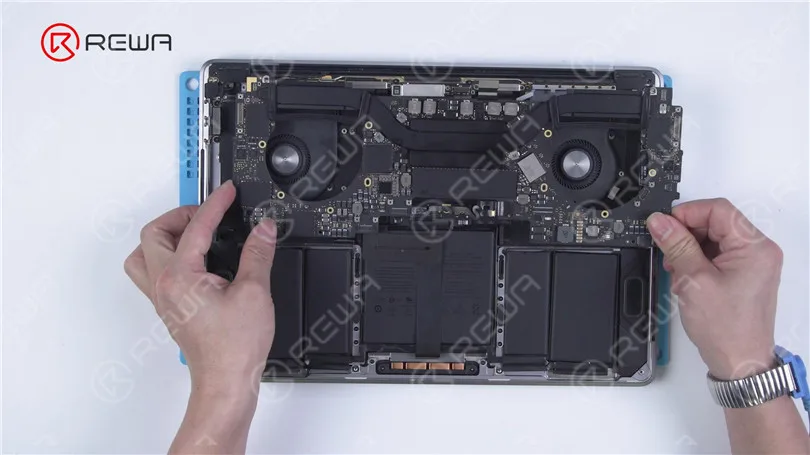
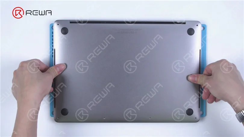
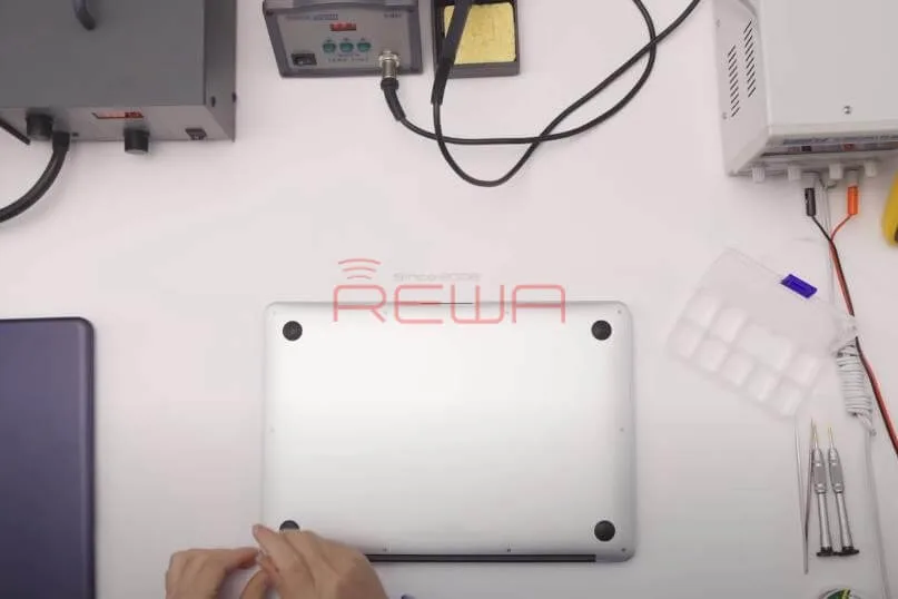
    2. Remove the lower case screws and casing.
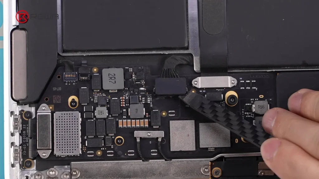
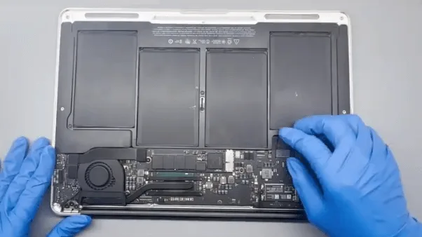
    3. Disconnect the battery cable.
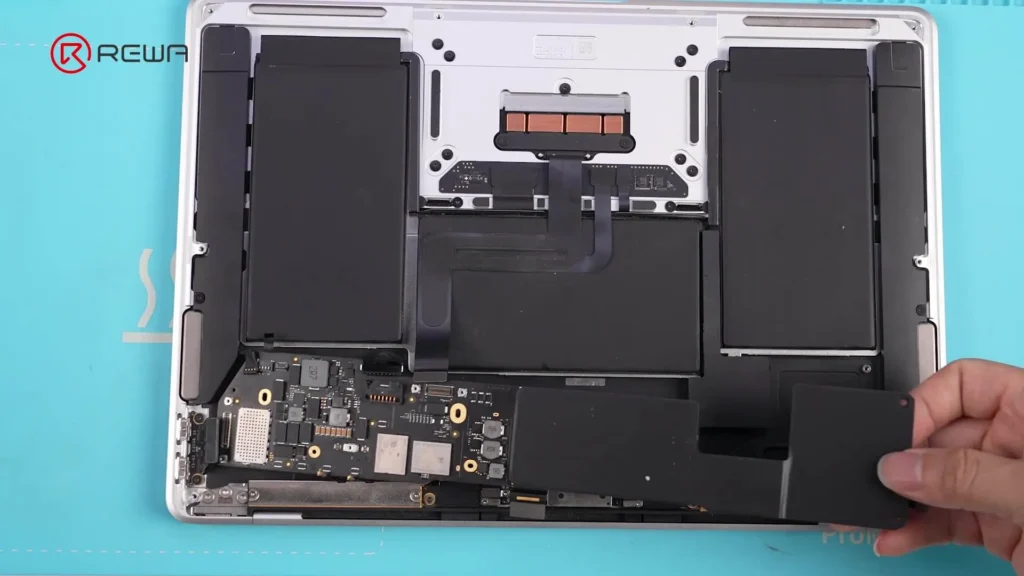
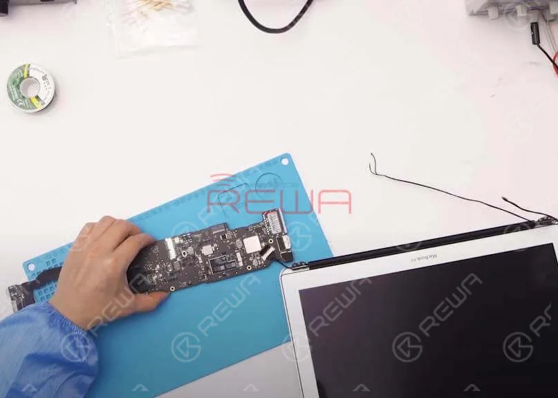
    4. Remove the motherboard:
      • Unscrew all mounting screws.
      • Remove the heat sink.

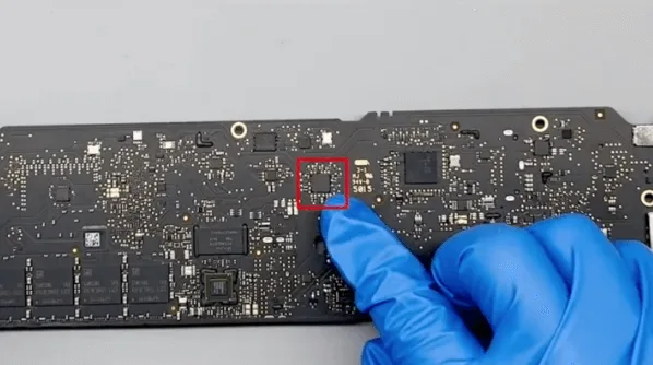
    Step 4: Remove the Faulty Wi-Fi Chip

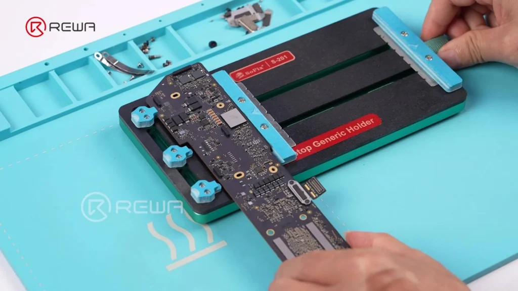
    1. Secure the motherboard using a PCB fixture.
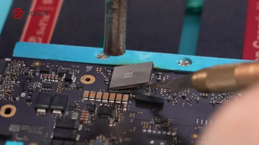
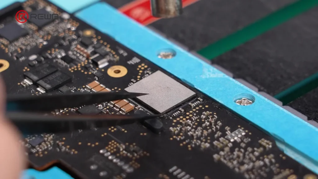
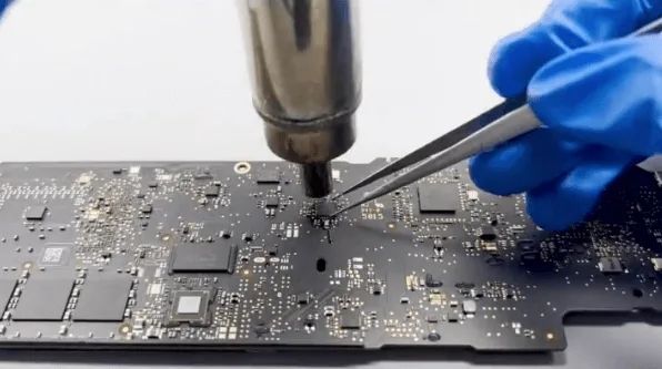
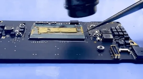
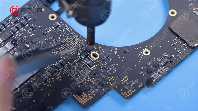
    2. Use a hot air gun to soften the adhesive around the chip.
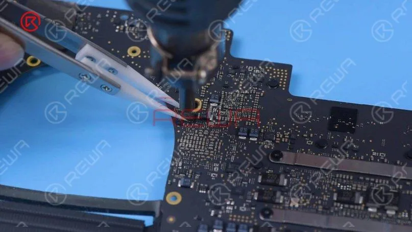
    3. Gently remove the adhesive with tweezers — do not directly heat the chip yet.
    4. Apply heat evenly by moving the hot air gun in a clockwise motion over the chip.
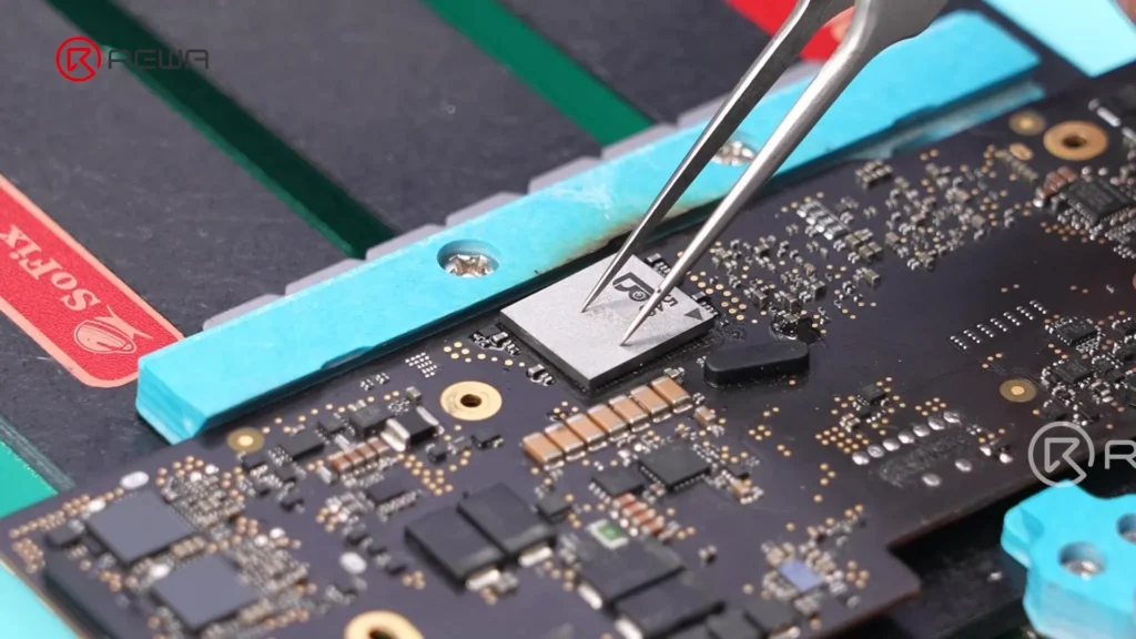
    5. Insert a pry tool under the chip and lift it gently.
    Step 5: Prepare the Solder Pads

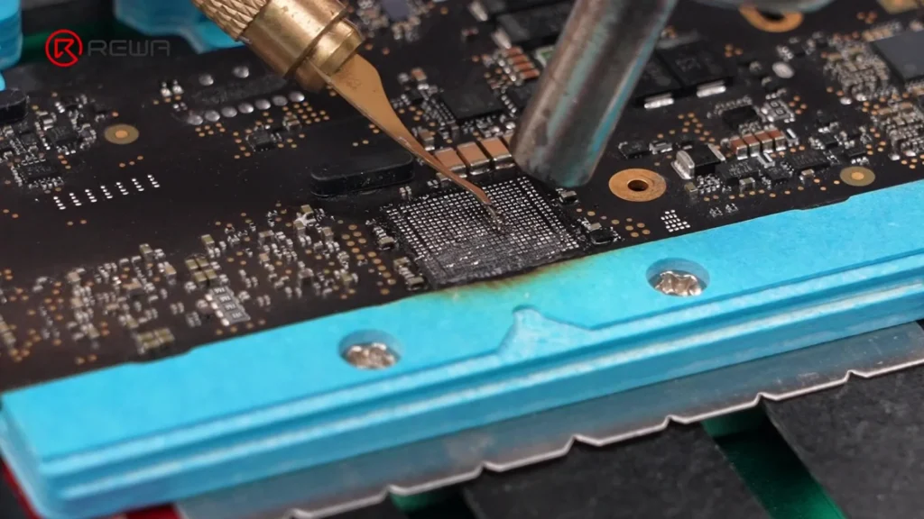
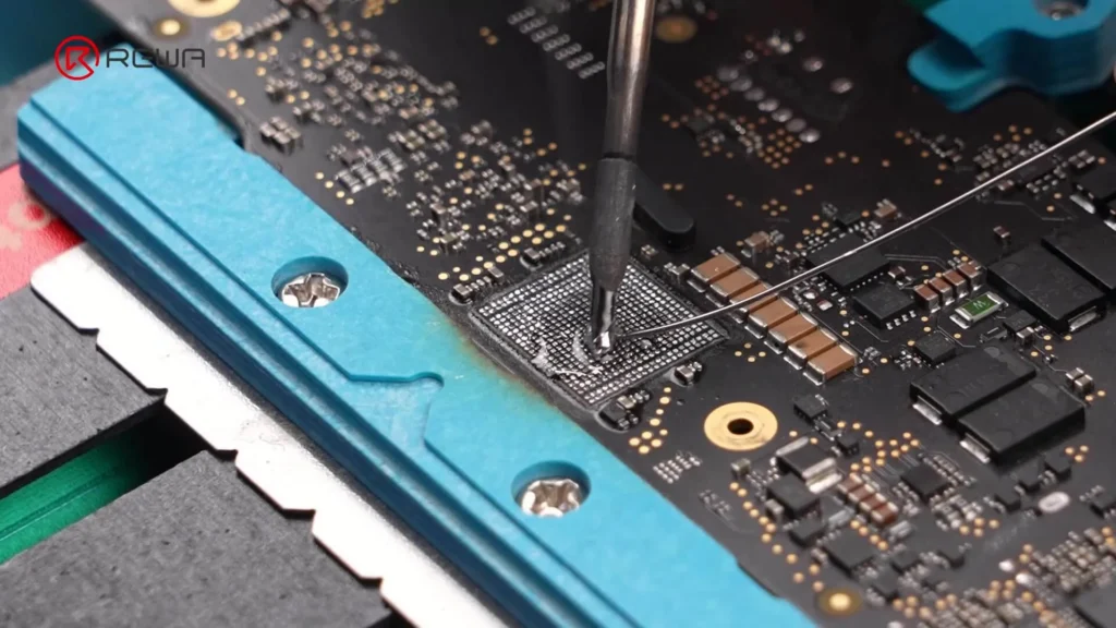
    1. Apply flux and medium-temperature solder to neutralize the high-temperature solder on the pads — this lowers reinstallation risk.
    2. Heat around the pads and remove black adhesive with a scraper.
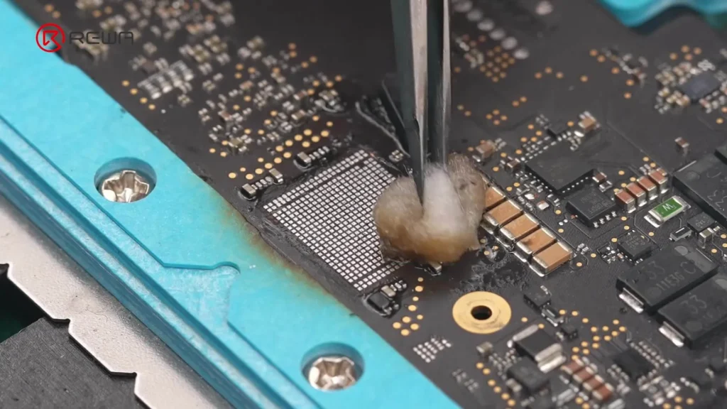
    3. Clean pads with PCB cleaner.
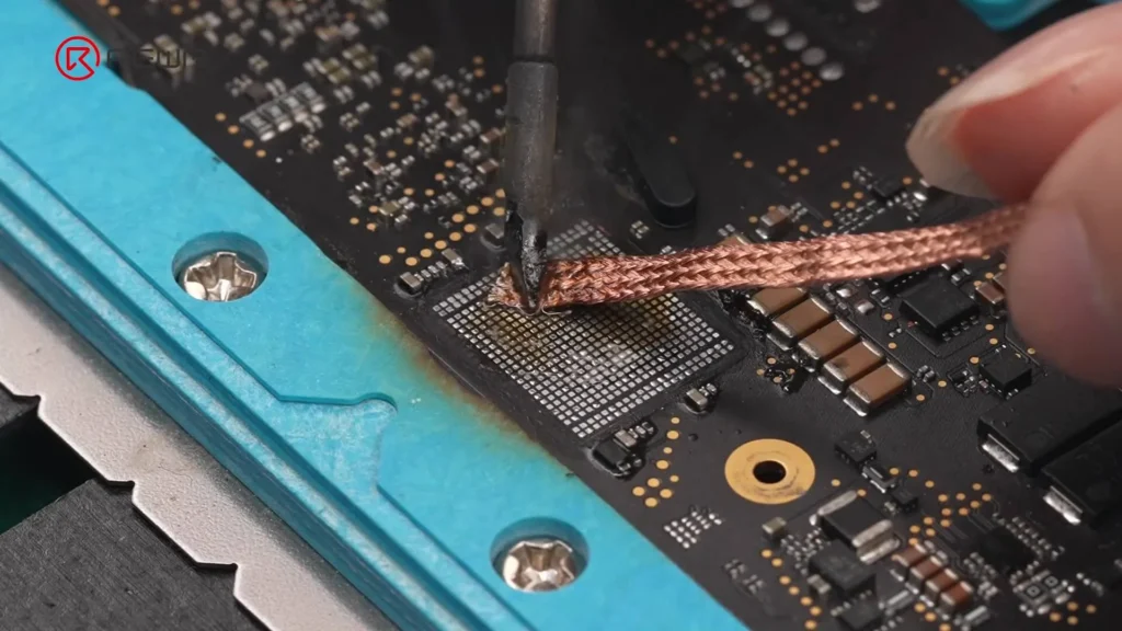
    4. Apply flux again and use solder wick to remove all remaining solder.
    5. Wipe pads clean with PCB cleaner-dampened cotton.
    Step 6: Program the New Wi-Fi Chip

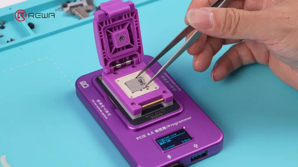
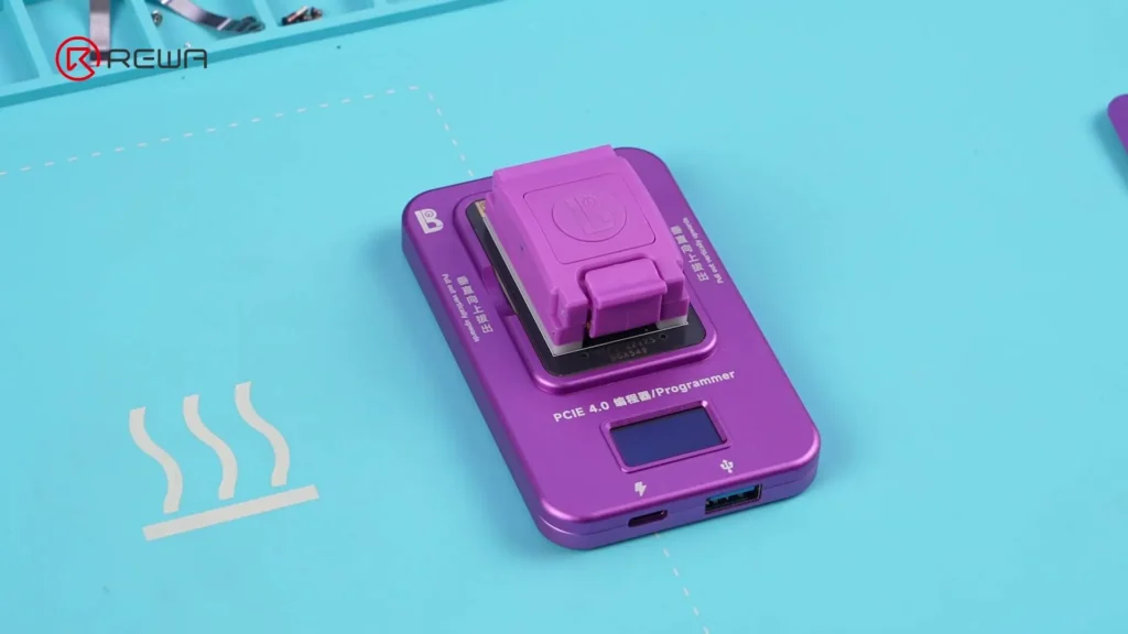
    1. Install the MacBook Wi-Fi repair module into a programmer.
    2. Insert the new Wi-Fi chip into the module.
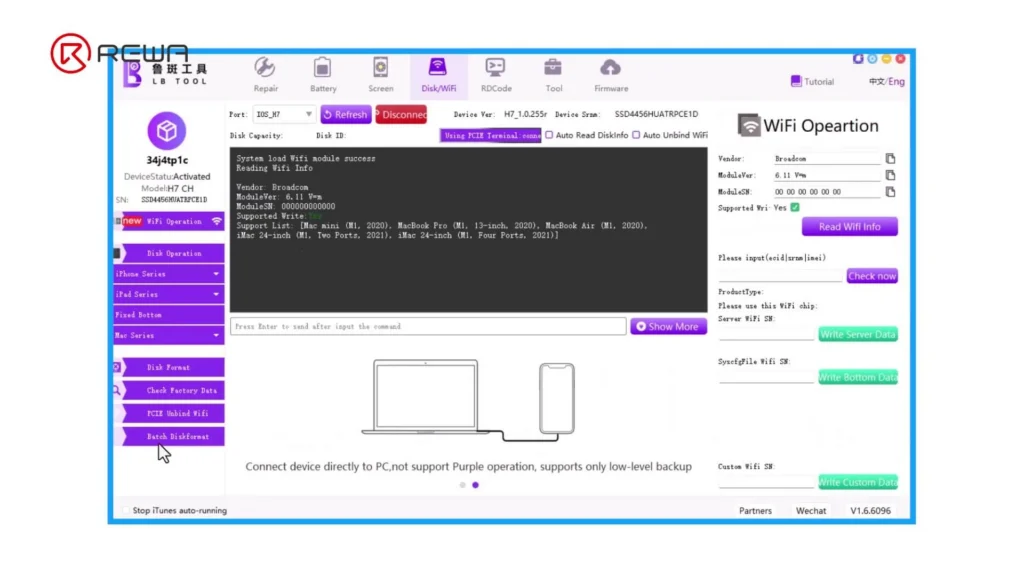
    3. Connect the programmer to a computer running LB Tool software.
    4. Wait for the software to read the new chip.
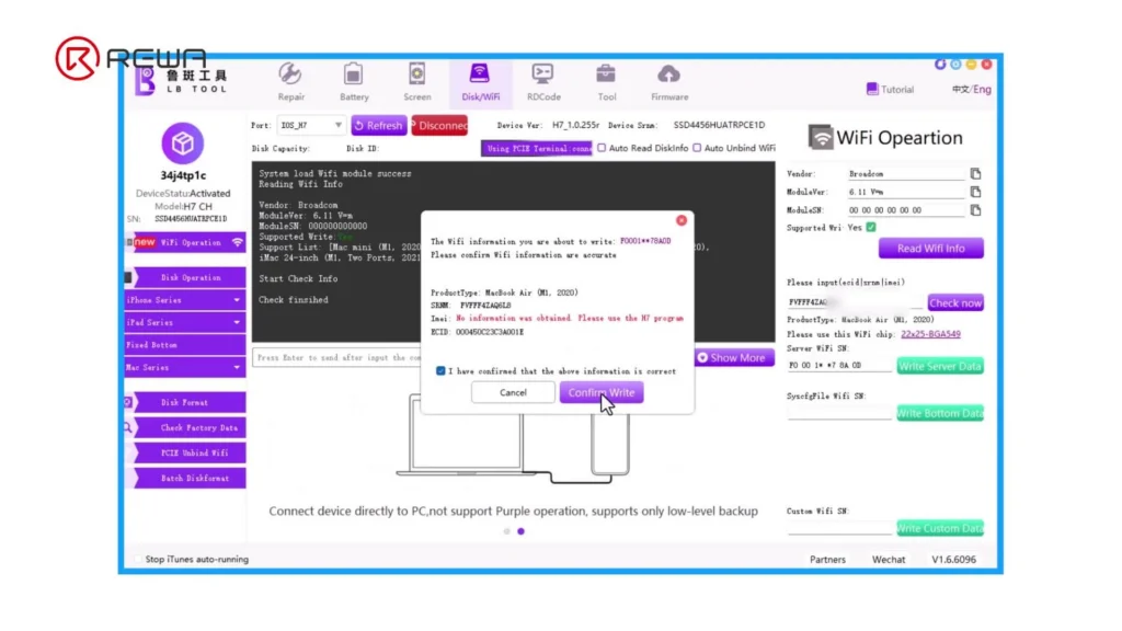
    5. Enter the ECID recorded earlier.
    6. Click Check Now — the required data fields will auto-populate.
    7. Click Write Server Data → confirm → Confirm Write.
    8. Wait for the write to complete — success is shown when “PASS” appears.
    Step 7: Reball and Install the New Chip

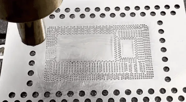
    Reballing ensures the chip has fresh, evenly-spaced solder balls for a secure connection.

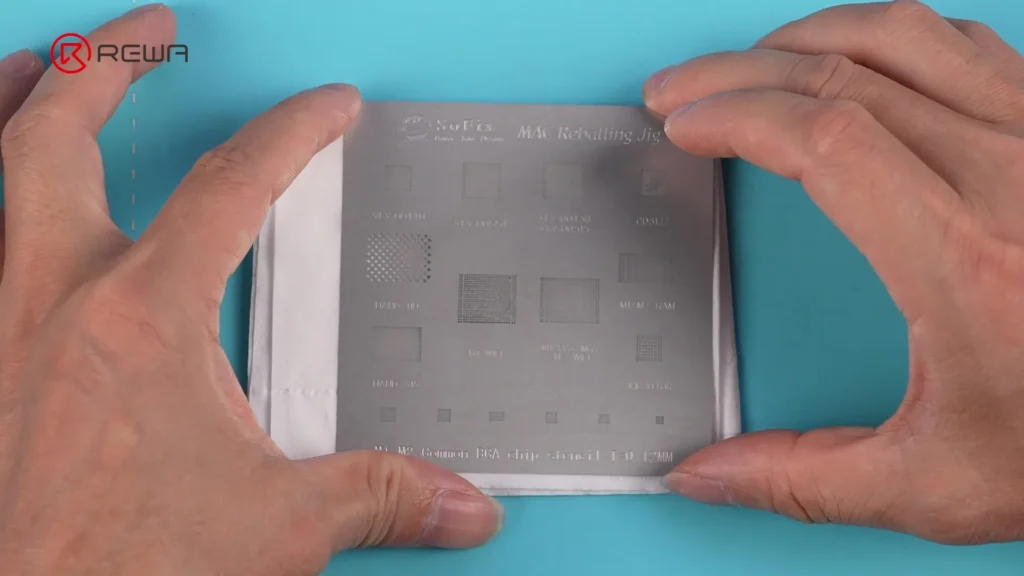
    1. Align a solder stencil with the chip pads.
    2. Spread medium-temp solder paste over the stencil.
    3. Heat with a hot air gun until solder forms balls.
    4. Apply flux to the chip pads.
    5. Heat the pads briefly to smooth solder balls.
    6. Apply flux to the motherboard pads.
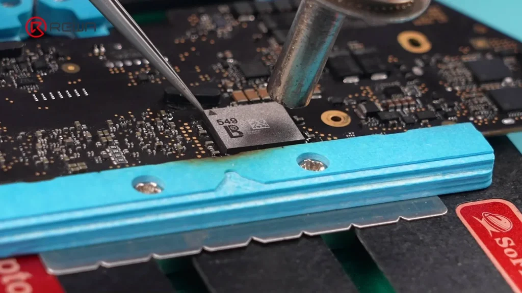
    7. Position the chip precisely using tweezers.
    8. Heat in a clockwise motion to secure solder joints.
    9. Tap gently with tweezers to confirm stability.
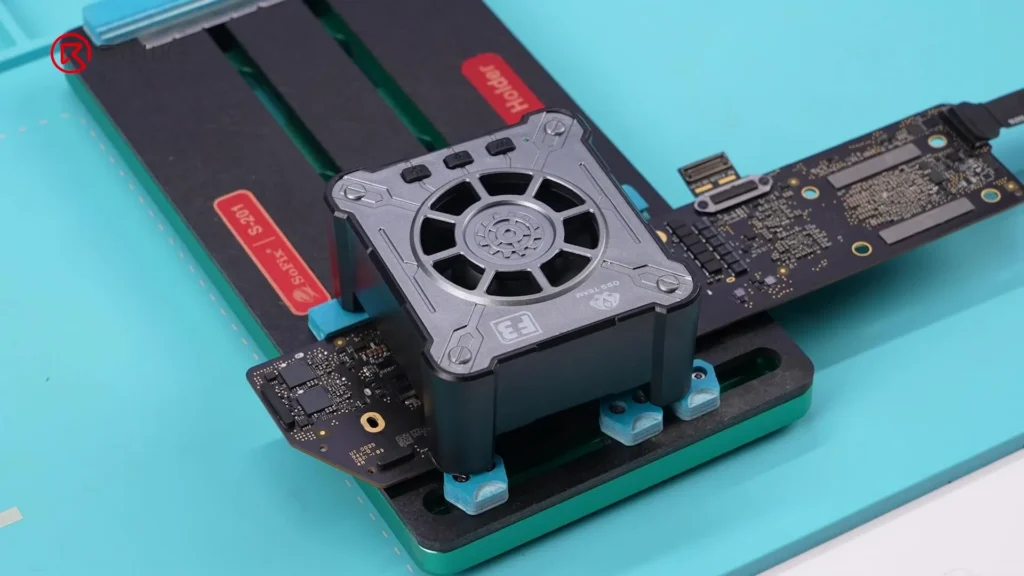
    10. Cool quickly using a fan.

    Step 8: Test and Reassemble

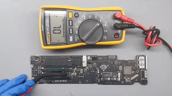
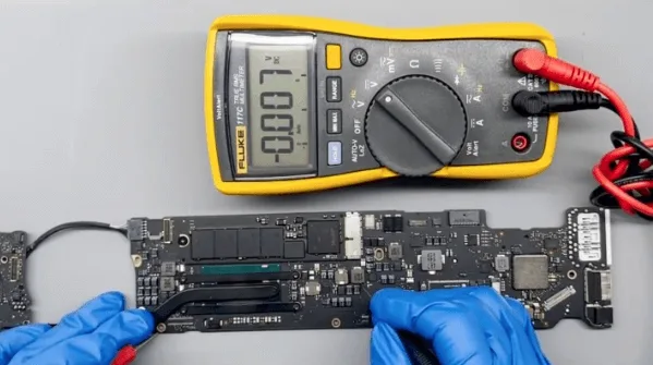
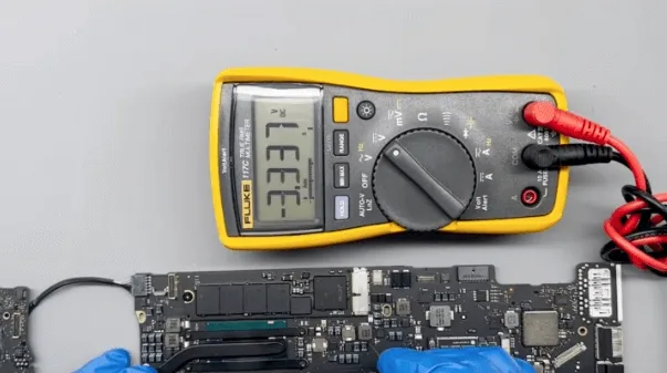
    1. Use a multimeter to test capacitors around the chip — readings should be normal.
    2. Reinstall the heat sink.
    3. Reinstall the motherboard.
    4. Reconnect the battery cable.
    5. Reattach the lower case.
    6. Connect a charger to re-activate the battery.
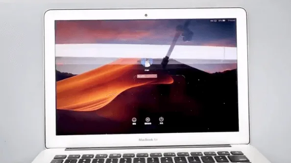
    7. Boot the MacBook and check Wi-Fi — it should now work.
    8. Verify ECID remains unchanged.

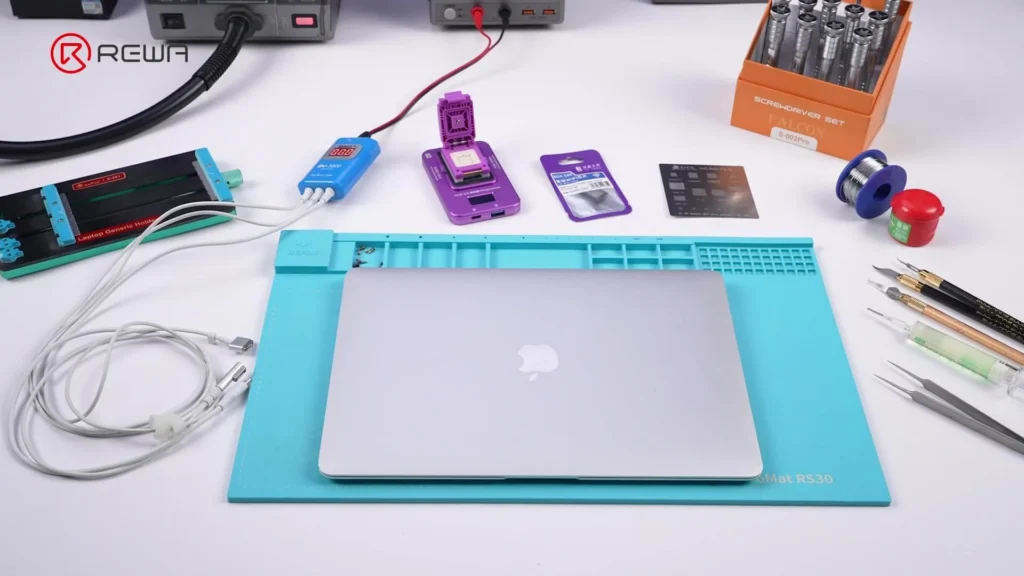
    Tools & Parts List

    Tools:

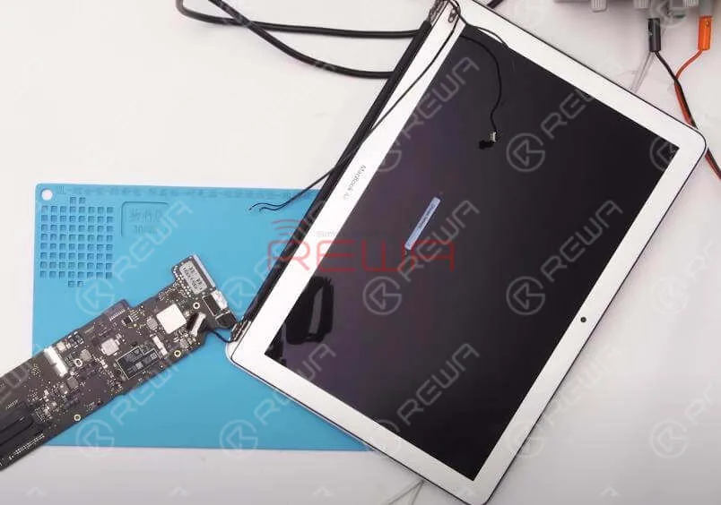
    macbook wifi not working repair

    Materials:

    • Flux
    • Medium-temp solder
    • Solder paste
    • PCB cleaner
    • Cotton swabs

    Parts:

    • New Wi-Fi chip (compatible with MacBook model)
    • MacBook Wi-Fi repair module
    • Programmer device (LB Tool compatible)

    Software:

    • LuBan Software

    FAQs

    What is ECID and why is it important?

    The ECID (Exclusive Chip ID) is a unique identifier for your MacBook’s components. When replacing the Wi-Fi chip, the ECID must be rewritten to the new chip to ensure compatibility with the motherboard.

    Can I perform this repair without professional tools?

    No — this procedure requires precision tools, soldering skills, and specific software. Attempting it without the proper equipment risks damaging the motherboard.

    Is replacing the Wi-Fi chip cheaper than replacing the motherboard?

    Yes, Wi-Fi chip replacement is significantly cheaper and more eco-friendly, as it avoids replacing the entire logic board.

    Will this fix also restore Bluetooth?

    Yes, since Wi-Fi and Bluetooth share the same chip, replacing it restores both functions.

    How long does the repair take?

    With the right tools and experience, it typically takes around 1–2 hours.

    Conclusion

    For years, MacBook Wi-Fi chip failure meant replacing the entire logic board — a costly and wasteful approach. Thanks to REWA Tech’s breakthrough method, it is now possible to replace the integrated Wi-Fi/Bluetooth chip on M-series MacBooks, preserving the original board and saving significant repair costs.

    With the correct tools, software, and skill, professional technicians and advanced DIYers can successfully restore full wireless functionality. Always take ESD precautions, use quality flux and solder, and ensure accurate ECID programming for a lasting repair.

  • Master MacBook Logic Board Repair with REWA

    Master MacBook Logic Board Repair with REWA

    Apple continued to grow its overall MacBook market-share in recent years as a leading Windows PC maker.

    According to the latest data, the MacBook now accounts for nearly 10 percent of all PCs currently in use.

    Meanwhile, the market for repairing these devices has also grown rapidly over the years.

    However, one can hardly get access to MacBook repair training courses due to a lack of repair engineers and schools.

    That’s why we carried out this MacBook training project to help you stand out among your competitors and double your profit.

    Course Description:

    The courses are designed to help new and experienced technicians master all levels of MacBook repairs and walk away with the knowledge and practical skills to immediately use in their business.

    REWA MacBook Logic Board Repair Training Course

    Course Schedule:

    Day 1: MacBook models and its logic board configuration introduction.

    Screen disassembly and assembly. MacBook spare parts replacement.

    Day 2: MacBook Pro A1502 booting sequence introduction.

    SMC chip disassembling and assembling. Liquid-damaged IC repair.
    Day 3: MacBook A1706, A1707 booting sequence introduction.

    BGA chip replacement with BGA Rework Station.

    Day 4: MacBook Air, MacBook Pro RAM & SDRAM upgrade.

    Change the graphics card settings on A1286. Chip soldering & desoldering. Logic board circuit Modification.

    Day 5: MacBook Air & Pro all models firmware unlocking and PIN code unlocking.

    On-site MacBook troubleshooting. Oscilloscope usage.

    Day 6: Common issues and fixes of MacBook. MacBook troubleshooting by current measurement.

    Course Duration:

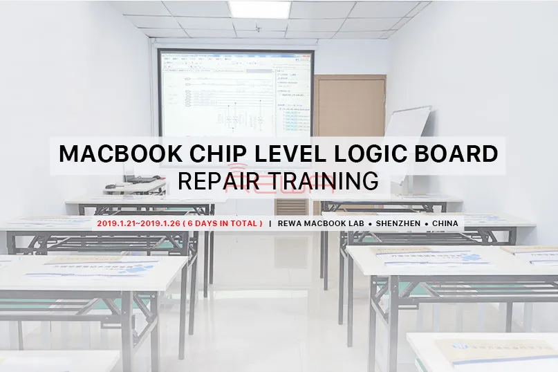
    21st, January 2019 – 26th, January 2019 (6 days in total)

    Training Location:

    REWA MacBook Lab, Shenzhen, China

    Training fee: Only USD 1499

    This price includes courses, materials, and translation.

    Costs like food, accommodation, and transportation are not included.

    Application Deadline:

    Jan. 12th, 2018 (Limited seats available.)

    Anybody who intends to improve their MacBook repair skills can take this course.

    The course will equip you with the advanced on how to repair the MacBook.

    Apply and get started on becoming a MacBook Repair Expert today.

    Everything is ready, just your actions ENROLL NOW

    Any further questions please feel free to contact us at: training@rewatechnology.com

  • Apple’s WWDC 2017: What You Need to Know

    Apple’s WWDC 2017: What You Need to Know

    apple wwdc 2017 what you need know

    Apple’s annual Worldwide Developers Conference, WWDC 2017, is happening in San Jose, CA, from June 5 to June 9 at the McEnery Convention Center. This event brings together developers and over 1,000 Apple engineers for sessions and networking.

    The first day usually kicks off with a keynote where Apple unveils upcoming software and occasionally introduces new hardware.

    Key Announcements:

    1. New iPad Pro:

      • The new iPad Pro comes in two sizes: 10.5-inch and 12.9-inch, with a stunning Retina display.
      • It offers powerful performance, simplicity of use, and runs on iOS, the world’s most advanced mobile operating system.
    2. Refreshed iMacs:

      • The latest iMacs feature new processors, cutting-edge graphics, innovative storage, and improved connectivity.
      • The Retina display is now brighter and more colorful, providing an immersive experience.
    3. iMac Pro:

      • The iMac Pro is the fastest and most powerful iMac to date, with a 27-inch 5K display and advanced internal components.
      • It’s designed for professional-level performance, featuring Intel Xeon processors, Radeon Pro Vega GPUs, and impressive storage and memory options.
    4. Mac OS High Sierra:

      • The newest Mac operating system, macOS High Sierra, focuses on reliability, capability, and responsiveness.
      • It includes under-the-hood updates and refines everyday features and apps.
    5. Other Announcements:

      • iOS 11 introduces new features for iPhone and iPad.
      • WatchOS 4 enhances the Apple Watch with smarter activity and workout features.
      • HomePod is a breakthrough home speaker with exceptional sound and intelligence.

    The event also showcased refreshed MacBooks, new watch bands, a Wireless Magic Keyboard with a Numeric Keyboard, and new iPad cases.

  • MacBook Air A1466 Not Charging Issue Repair

    MacBook Air A1466 Not Charging Issue Repair

    MacBook Air A1466 Not Charging Issue Repair

    Defect Phenomenon

    The MacBook cannot charge after not using for a few days.

    Troubleshooting

    First, let’s check the cosmetic of the MacBook. Everything looks fine, there are no obvious drop or water damage traces.

    macbook air a1466 not charging issue repair the

    Then let’s remove the screws on the bottom with a screwdriver.

    macbook air a1466 not charging issue repair remove the screws on bottom

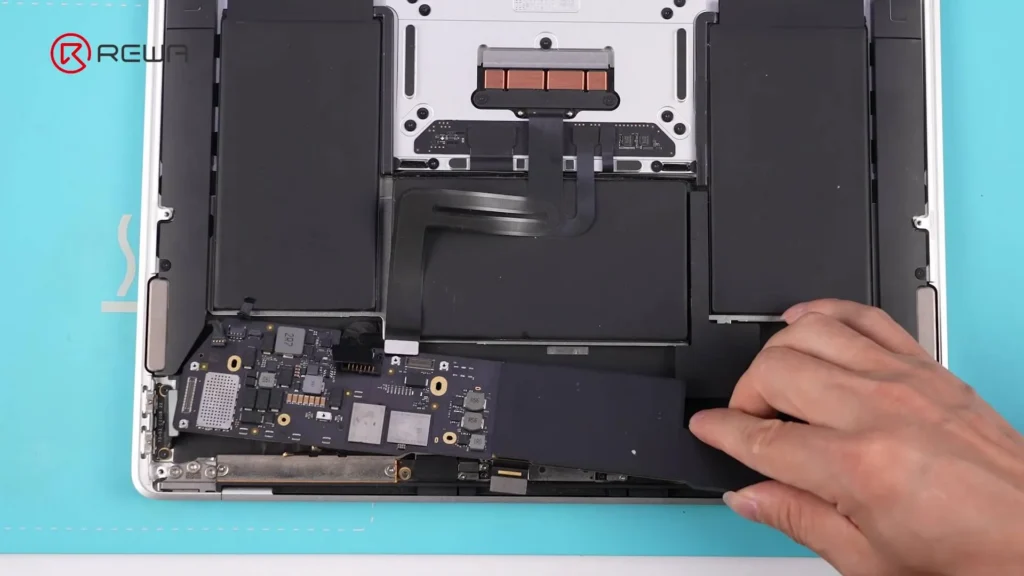
    Open the D cover (or bottom cover), and we can see the motherboard also looks good from the cosmetics.

    macbook air a1466 not charging issue repair the motherboard also looks

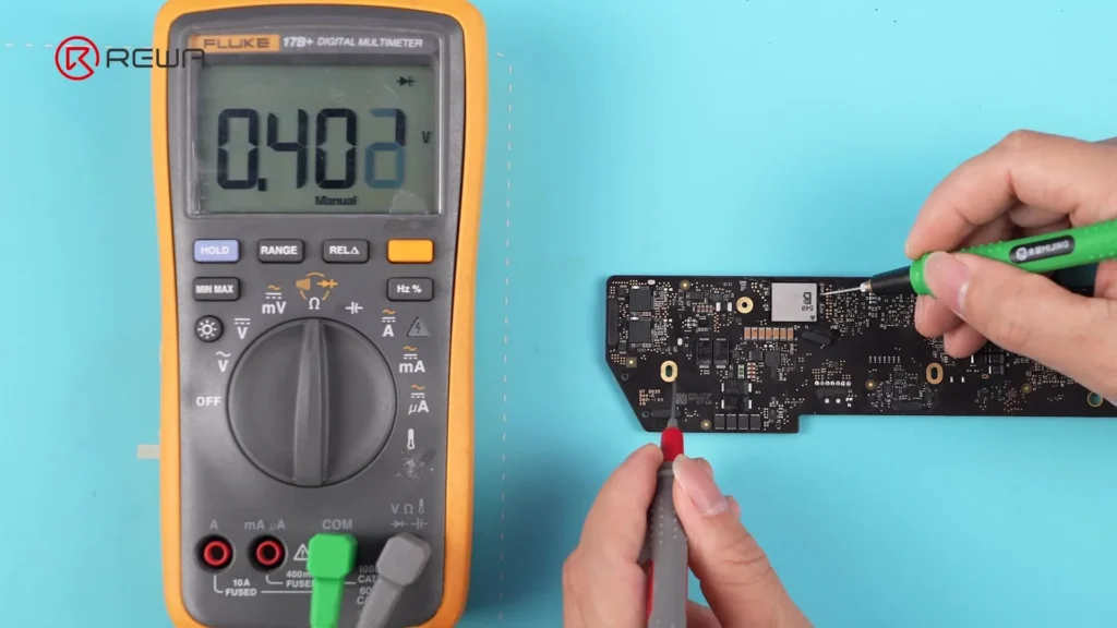
    Detach all the flex cables and take out the motherboard, since it’s cannot charge issue let’s carefully check the large inductors’ diode values first.

    macbook air a1466 not charging issue repair large inductors

    macbook air a1466 not charging issue repair measure all the diode values

    To do this, we can confirm whether there is a short on the inductors or not, to avoid damage to the CPU later when connecting with the DC power supply.

    After checking, there’s no shortage of inductors. Then let’s power the motherboard with the DC power supply machine.

    macbook air a1466 not charging issue repair power the motherboard

    The boot current was fixed at 30mA, which means the CPU is not working.

    macbook air a1466 not charging issue repair the boot current fixed at

    Based on the standby sequence, let’s measure the voltage on the relative rails first

    macbook air a1466 not charging issue repair the standby sequence

    (the main power supply is around 8.6V, OK!)

    Then measure the 35V standby chip voltage, normally the voltage should be fixed at 3.3V.

    But the voltage value keeps jumping from 3.3V to 0V during the measuring.

    macbook air a1466 not charging issue repair 3v to ov voltage

    macbook air a1466 not charging issue repair 3v voltage

    Based on the repair experience, this chip is a common defective chip, is it possible the 35V standby chip is damaged?

    Let’s find it on the motherboard and replace it with a new one directly to have a try.

    macbook air a1466 not charging issue repair the 35v standby chip

    macbook air a1466 not charging issue repair remove the standby chip

    After the standby chip replacement, let’s connect with the DC power supply machine to test again.

    This time the standby voltage is fixed at 3.3V, but the boot current is still fixed at 30mA.

     A1466 Not Charging

    This means there’s still another problem with the motherboard.

    • There’s no working voltage on the CPU
    • the 3.3V voltage on the PCH is OK
    • based on the working sequence, measuring the voltage on the power button is also OK
    • There’s no voltage from PCH to Power Management IC

    macbook air a1466 not charging issue repair the voltage on power button

    Based on the above measurement results, we can make the preliminary judgment that the issue is caused by the PCH. In the model with the integrated graphic card, the PCH and CPU are also integrated into a chip.

    macbook air a1466 not charging issue repair pch damage

    So we can only replace the CPU chip

    1. remove the NAND flash memory board and heat sink
    2. remove the thermal grease on the chip

    macbook air a1466 not charging issue repair remove nand and heat sink

    3. then use the sculpture knife to scratch on the PCB surface slightly to mark the location/layout of the CPU chip. Later when we solder back the CPU, this mark can be used for alignment reference

    macbook air a1466 not charging issue repair cpu location mark

    The motherboard of the MacBook is much larger than iPhones, to avoid deformation we should use the specified PCB heating station machine for chip replacement.

    Another method, if you are experienced enough, is the PCB heating pad + the hot air gun also works fine.

    macbook air a1466 not charging issue repair work fine

    CPU replacement process

    1. Apply with solder paste flux
    2. heat with the hot air gun evenly till the tins are melted, then pick up the CPU with the tweezer slightly
    3. Clean the pads on the PCB with solder wick and soldering iron
    4. Reball the good CPU with the stencil and soldering tin balls or solder paste
    5. Then apply solder paste on the PCB, align the CPU chip, and heat with the hot air gun to solder the CPU

    macbook air a1466 not charging issue repair remove the cpu

    macbook air a1466 not charging issue repair reball the cpu

    macbook air a1466 not charging issue repair pay attention to the

    Finally, the CPU chip is well soldered, then we can add some thermal grease then install the heat sink and the NAND flash card.

    macbook air a1466 not charging issue repair cpu is well sodered

    Connect with the DC power supply to boot again, the current is normal this time.

    macbook air a1466 not charging issue repair normal boot current

    Assemble the MacBook to have a test, the MacBook can be booted normally and all the functions are also OK

    macbook air a1466 not charging issue repair the can be booted normally

    Summary

    The cannot charge issue gets fixed by the 35V standby chip and CPU chip replacement.

  • How to Fix M1 MacBook Air Won’t Turn On

    How to Fix M1 MacBook Air Won’t Turn On

    Today we will share how to fix an M1 MacBook Air that won’t turn on. Supplying power to the motherboard, we find that the voltage jumps back and forth between 0V and 5V. The measurement tells us that the working conditions of voltage boost from 5V to 20V are good. After rewriting the ROM data of CD3217 with U301, the MacBook now turns on normally.

  • How to Fix M1 MacBook Air Won’t Turn On

    How to Fix M1 MacBook Air Won’t Turn On

    U301 is a tool that helps resolve the issue of an unresponsive M1 MacBook Air. It enables the reading and writing of data on the USB C ROM chip. Compatible with all MacBooks that have a Type C port from 2016 to 2020, U301 comes with the original ROM data for these devices. Today, we will explain how to utilize U301 for fixing the problem of a non-booting M1 MacBook Air.

    Initially, upon attempting to power on the MacBook Air, we encounter the issue where the device fails to turn on.

    How to Fix M1 MacBook Air Won't Turn On

    The MacBook Air is disassembled to conduct additional tests. The back cover is removed and the battery is disconnected. Next, the screws and motherboard are taken out, and the battery flex cable is detached. Finally, the heatsink on the motherboard is removed.

     MacBook Air for further testing

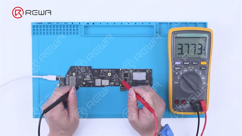
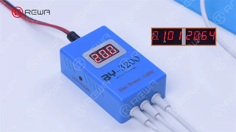
    Connect the BY3200 to the DC power supply and provide power to the motherboard. Observe erratic fluctuations in current and voltage, with the voltage oscillating between 0 volts and 5 volts. This indicates an unstable boost in the power supply line of the motherboard, leading to the issue of it not turning on.

    BY3200 to the Direct Current Supply

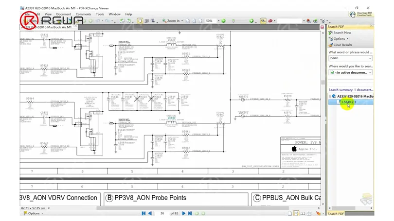
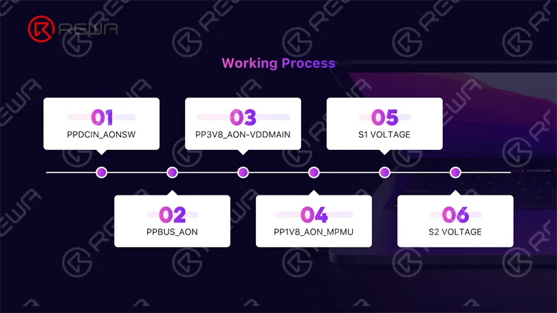
    After examining the bitmap, we locate L5840 along the primary power supply line. By referring to the drawing, we search for L5840 and discover that it corresponds to the output voltage of PP3V8 AON VDDMAIN. Subsequently, we proceed to measure the voltage of L5840, which is confirmed to be within the normal range.

    check the bitmap and find L5840
    L5840 is PP3V8 AON VDDMAIN

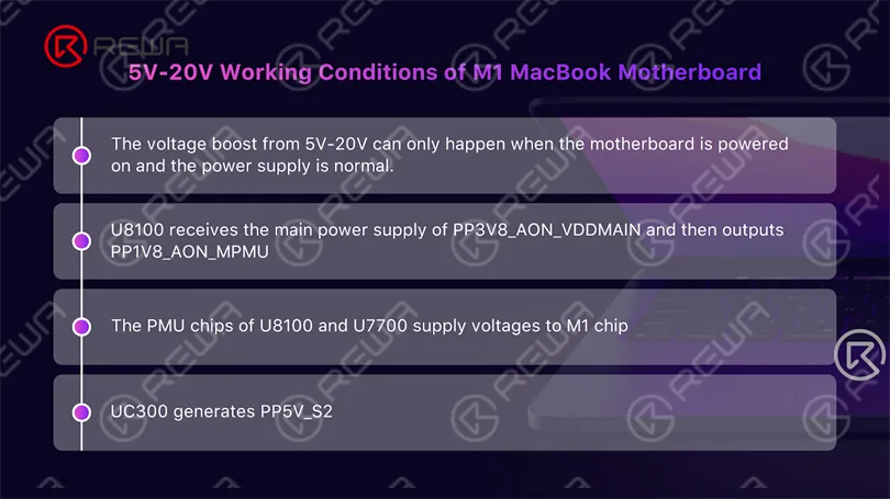
    Next, we assess the operational environment for voltage amplification ranging from 5 volts to 20 volts.

    5 volt to 20 volts
    working conditions

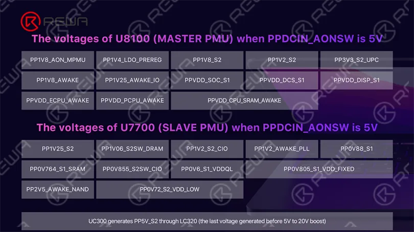
    Locate U8100 on the bitmap, and then search for U8100 on the drawing to find the listed output voltages.

    U8100 on the bitmap
    output voltages of U8100

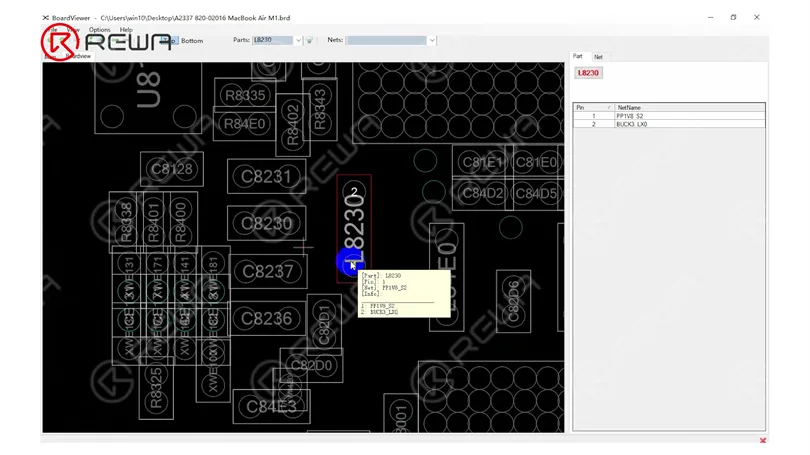
    The voltage in standby mode usually requires measurement. Consider L8230 as a case in point. Locate L8230 on the bitmap and verify that the voltage is within the normal range.

    take L8230 as an example

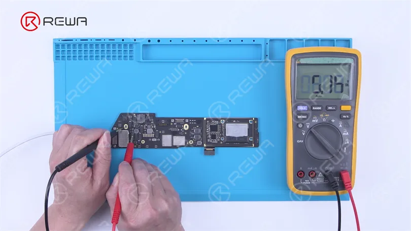
    Continuously measure additional inductors and confirm normal voltages. Proceed with the measurement of LC320 and locate its corresponding position on the drawing. The output voltage for LC320 is PP5V S2, which is within the expected range.

    measuring other inductors
    Search LC320

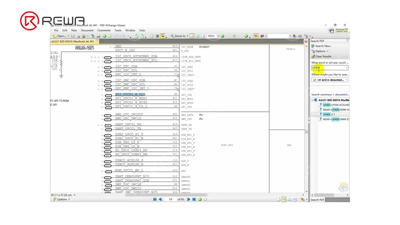
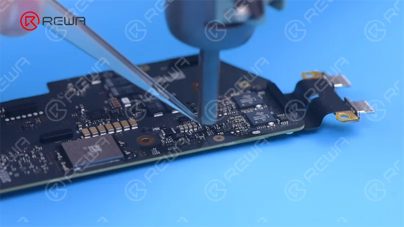
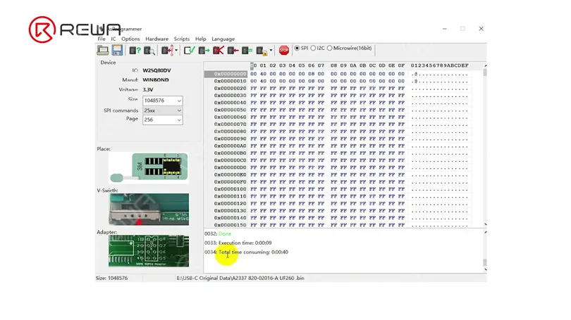
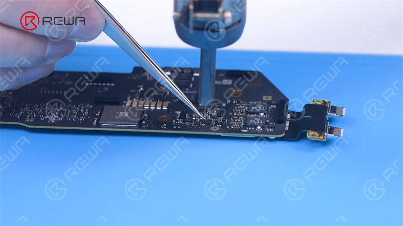
    The voltage boost from 5 volts to 20 volts has been determined to have favorable working conditions. Consequently, it is necessary to rewrite the ROM data of CD3217. Locate the ROM chip labeled UF400 on the provided drawing and identify the SPI CLK signal. Proceed to locate the UF260 ROM chip on the bitmap and proceed with its removal. Begin by applying Paste Flux, and then use a Hot Air Gun at 420 °C and airflow 4 to remove the chip.

    Hot Air Gun at 420 °C and airflow 4

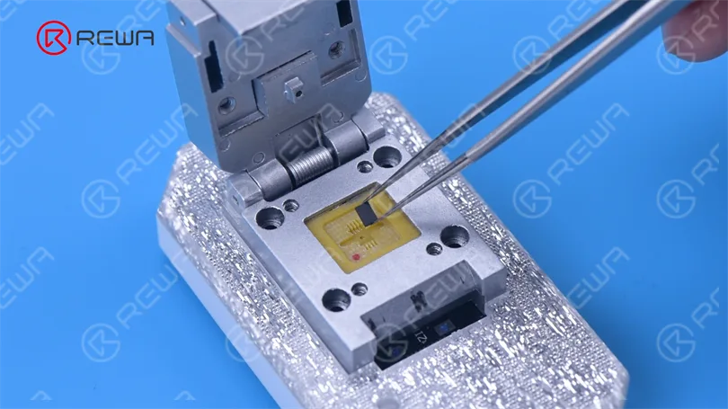
    Attach the chip to U301, ensuring that the pin of the chip is properly aligned. Proceed to connect U301 with a Windows computer.

    chip to U301

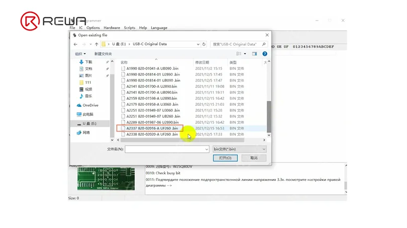
    Start by opening the software, then click on “Read ID”. Choose the appropriate file and click “Open file”. Next, select “USB C Original Data” and locate the matching model.

    Clicking on “Auto Program” will result in the successful writing of the data.

    Auto Program
    How to Fix M1 MacBook Air Won't Turn On

    Detach the chip. Reinstall the chip back into the motherboard. Connect the motherboard to power. The voltage, which has been boosted from 5 volts to 20 volts, returns to normal. The current jump is also good, indicating that the motherboard is powered on.

    How to Fix M1 MacBook Air Won't Turn On
    How to Fix M1 MacBook Air Won't Turn On

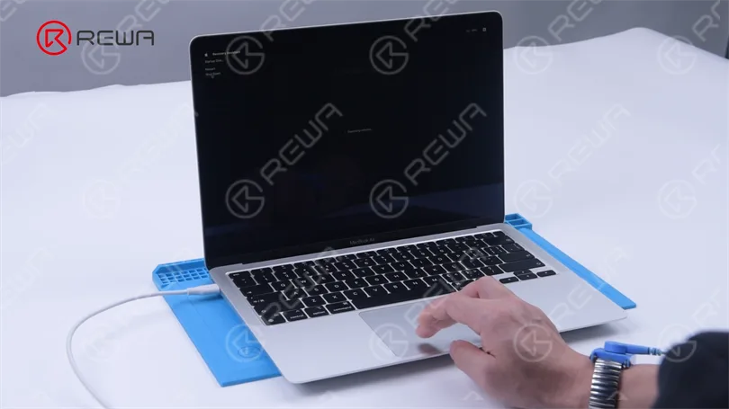
    After disconnecting, activate the battery to ensure the MacBook can turn on. Once activated, proceed with installing the motherboard for testing. The MacBook now powers on without any issues, indicating that the fault has been resolved.

    How to Fix M1 MacBook Air Won't Turn On

    U301 is available for purchase on REWA Shop. For further information, you can reach out to our sales team. More M1 MacBook repair content will be shared by REWA in the future. If you have any specific topics related to M1 MacBook repair that interest you, please feel free to leave a comment.

  • MacBook Battery Expansion: Causes & Solutions

    MacBook Battery Expansion: Causes & Solutions

    Why is the MacBook battery expanding?

    The MacBook uses a lithium-ion battery. The two ends are the positive electrode and the negative electrode.

    The middle part is the electrolyte that brings the lithium-ion to the other end from one end. Simply put, it charges and discharges.

    In this process, the electrolyte and moisture chemically react, producing hydrogen, carbon dioxide and alkane compounds.

    The outer casing of the battery is therefore extruded, causing a swollen battery.

    There are three common reasons: the battery is used for a long time; the battery is being charged for a long time; the battery is in a high-temperature environment.

    MacBook battery expanding common phenomenon

    The internal construction of MacBook is quite compact.

    When the battery gets swollen, it will first affect the touchpad above the battery.

    The touchpad cannot be pressed.

    What’s worse, the touchpad protrudes.

    Another situation is that the MacBook feels unstable, and there is a hump at the bottom.

    How to prevent macbook battery expanding

    • Use the original factory-certified charging line.
    • MacBook is not in use, I have been allowing the battery in a 100% full power mode.
    • Do not let MacBook batteries are in an environment that has more than 40 degrees in length.
  • How to Remove MacBook ID Activation Lock by T203

    How to Remove MacBook ID Activation Lock by T203

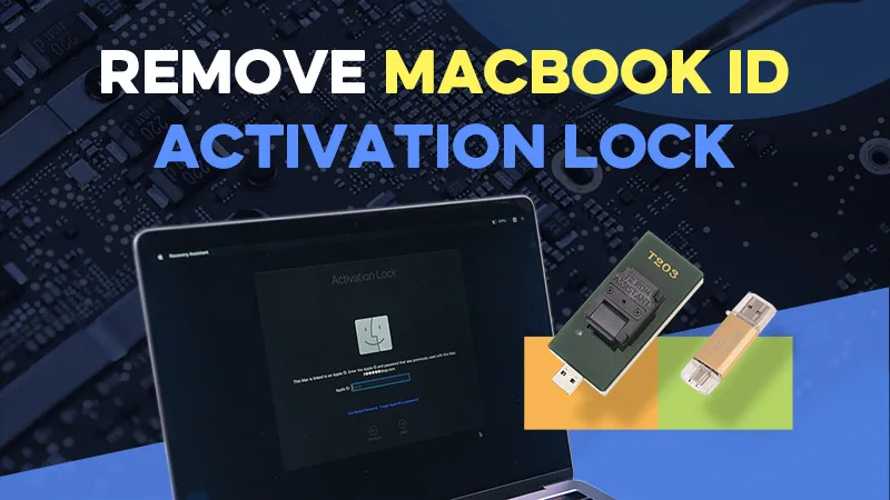
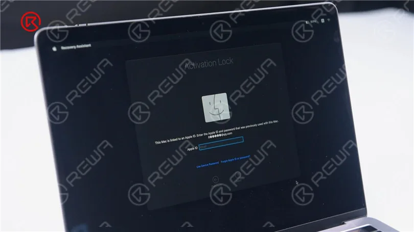
    MacBook users occasionally encounter the frustrating issue of being locked out of their devices due to the Activation Lock, which can occur after a system restore. Forgetting the Apple ID and passcode can lead to this predicament, rendering the MacBook inoperable.

    To regain access, you’ll need to remove the Activation Lock. In this article, we’ll introduce you to a tool called T203, designed for unlocking Activation Lock on MacBooks, particularly those equipped with the T2 chip manufactured from 2018 to 2020. We’ll guide you through the process step by step.

    Getting Started

    Before diving into the removal process, make sure your MacBook is powered on and displaying the Activation Lock screen. Once you’ve verified this, you can proceed.

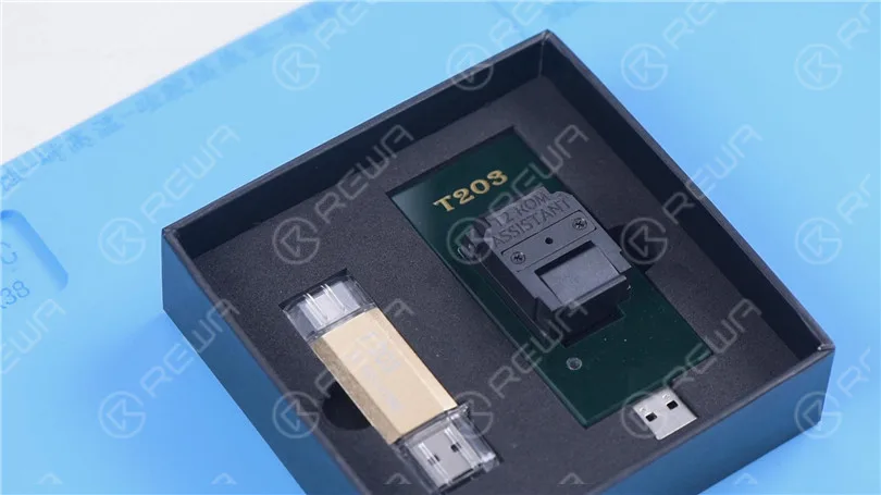
    T203 includes two tools: T203 USB flash drive and T203 ROM seat. T203 is mainly used to remove the EFI lock, pin code lock, and bypass the iCloud activation lock of 2018-2020 MacBook with the T2 chip.

    How to Remove MacBook ID Activation Lock by T203

    First of all, let’s turn on the MacBook. Activation lock is showing.

    How to Remove MacBook ID Activation Lock by T203

    Then we will use T203 to unlock the activation lock. Turn the MacBook off firstly. The MacBook model is A1989.

    Detach the motherboard and find the T2 ROM chip. Set the temperature and airflow of the Hot Air Gun at 425 °C and 3 respectively to remove the T2 ROM chip.

    How to Remove MacBook ID Activation Lock by T203
    How to Remove MacBook ID Activation Lock by T203

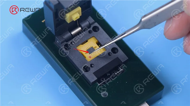
    Attach the chip to the specialized seat of T203. Align pin 1 of the chip with pin 1 of the seat.

    How to Remove MacBook ID Activation Lock by T203

    Connect T203 to computer and open “Programmer Software” folder. Begin writing unlock data.

    How to Remove MacBook ID Activation Lock by T203

    Unplug T203. Then we install the chip on the motherboard. Solder the chip back on the motherboard with Hot Air Gun at 425 °C and airflow 3.

    How to Remove MacBook ID Activation Lock by T203

    Put the motherboard back on the MacBook.

    How to Remove MacBook ID Activation Lock by T203

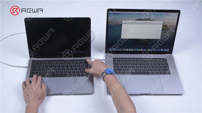
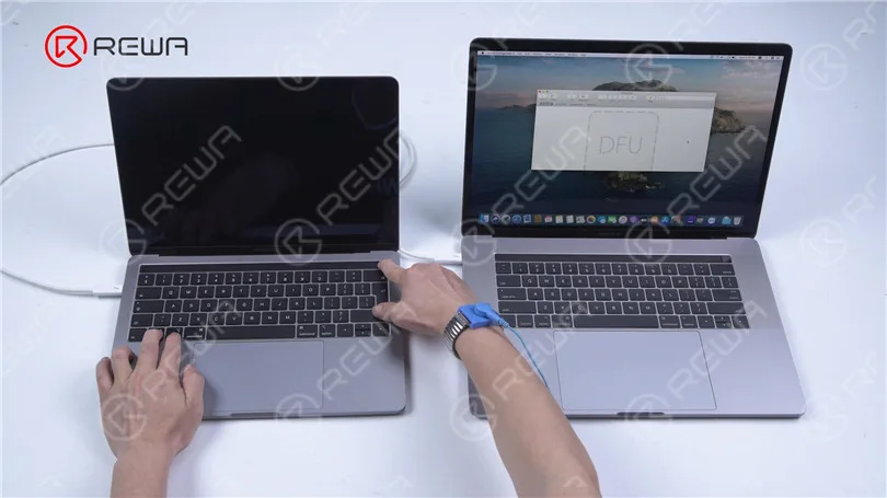
    After the data have been written, the MacBook is in DFU mode. The MacBook is unable to turn on. Connect the MacBook to another MacBook with a data cable.

    Please plug the cable into the left bottom Type-C.

    How to Remove MacBook ID Activation Lock by T203

    Open Apple Configurator 2. Right click to select “Restore”. Begin restoring.

    How to Remove MacBook ID Activation Lock by T203

    The lock sign on the screen indicates that the restoring has finished. Long press start button with one hand. Press touch panel with another hand.

    How to Remove MacBook ID Activation Lock by T203

    The touch panel is unresponsive, which means that the MacBook is turned off. Release the power button and then press the power button again. Press Control-Option-Shift-Power button to get the MacBook into DFU mode.

    How to Remove MacBook ID Activation Lock by T203

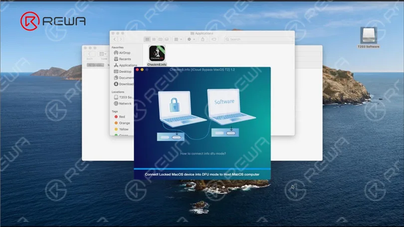
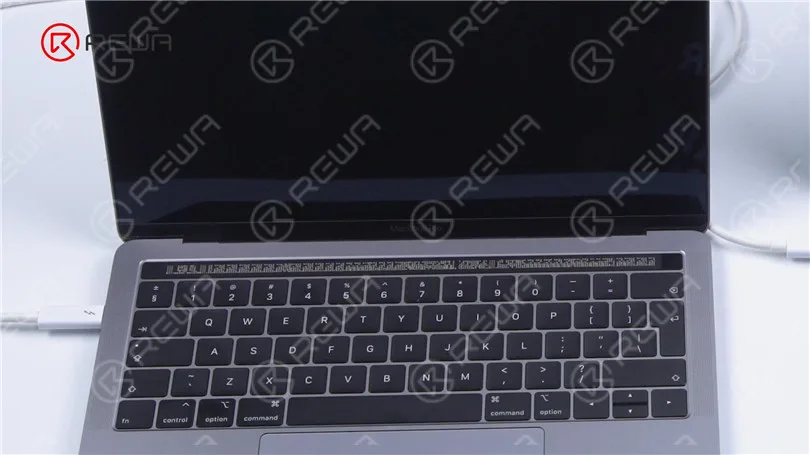
    Plug in the T203 USB to read the MacBook data. The MacBook data is successfully read if the Touch Bar has shown some images.

    How to Remove MacBook ID Activation Lock by T203
    How to Remove MacBook ID Activation Lock by T203

    Bypassing activation lock is ongoing.

    How to Remove MacBook ID Activation Lock by T203

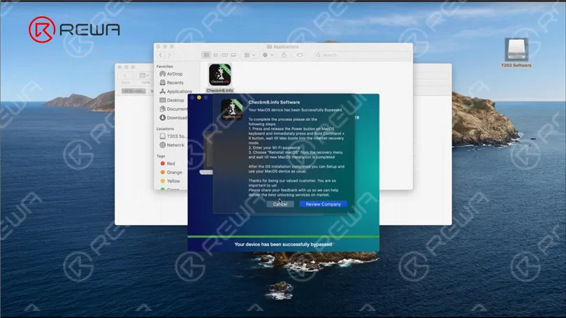
    We can see that bypassing has succeeded. Click “Cancel”. The device is successfully activated.

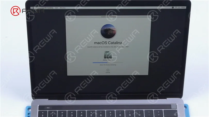
    Unplug the data cable. Press the power button. The MacBook shows no system. Turn the MacBook off. Press Command-R. Enter the system installation interface. Start reinstalling.

    How to Remove MacBook ID Activation Lock by T203

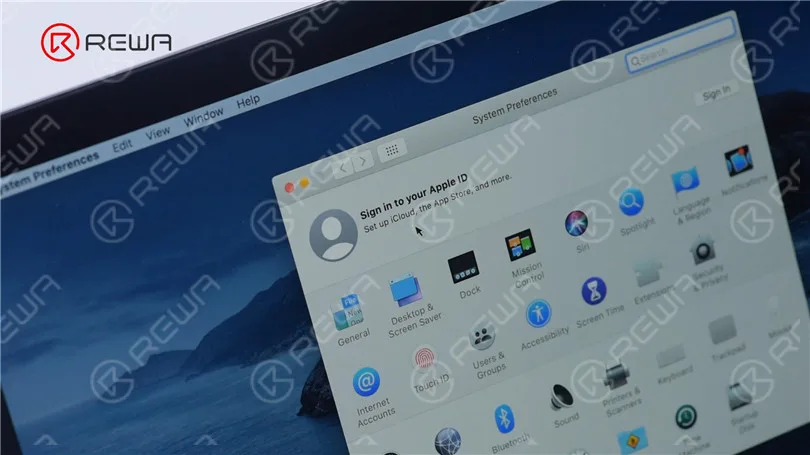
    Connect the MacBook with power. The ID of the MacBook is successfully removed. The activation has succeeded.

    How to Remove MacBook ID Activation Lock by T203

    You can buy T203 on REWA shop. Please feel free to leave a comment on MacBook repair topics that you are interested in.

    Watch the video below to see how we remove MacBook activation lock by T203.

    Conclusion

    With T203, removing the Activation Lock on your MacBook is made possible. This guide has provided a step-by-step explanation of the process. Remember that these methods should only be used for legitimate purposes, such as unlocking a MacBook you own but have forgotten the credentials for. It’s essential to exercise caution and always adhere to ethical and legal standards.

  • Power ON All MacBook with 1 Cable – MacBook Power Cable (BY-3200)

    Power ON All MacBook with 1 Cable – MacBook Power Cable (BY-3200)

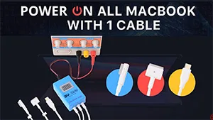
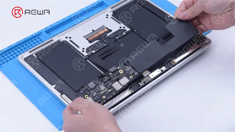
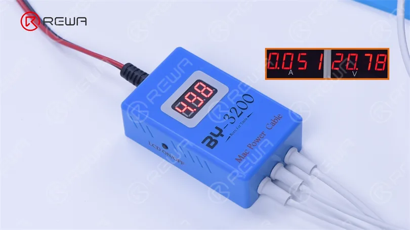
    Today, REWA Lab will introduce the MAC Power Cable (BY-3200), a boot cable product for MacBook repair. The BY-3200 features 3 interfaces (Type-C, T-style, and L-style) for the whole series 2008-2021 MacBook, providing power for different MacBook by simply connecting to a DC power supply. The BY-3200 mainly supports different power of fast charging, start-up and system entry with a single motherboard, boot current reading, etc.
    Recommended Items:

  • An Efficient Way to Diagnose MacBook Faults and Fix Serial Number (EBC-820)

    An Efficient Way to Diagnose MacBook Faults and Fix Serial Number (EBC-820)

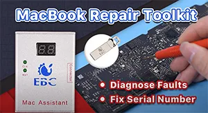
    In daily MacBook repair, motherboard component failure is the most common problem. For repair technicians, the most complicated process is not repairing, but finding the fault. In response to this situation, we introduce a MacBook repair assistant EBC-820 that can help repair technicians pinpoint the fault before repair. Check out this video and see how EBC-820 works!
    Products recommended in this video:

  • How to Fix MacBook Pro that Won’t Turn On

    How to Fix MacBook Pro that Won’t Turn On

    Today we will share a case about repairing a MacBook Pro 13″2018 (A1989) that won’t turn on.

    Press the power button.

    The MacBook won’t turn on.

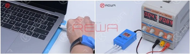
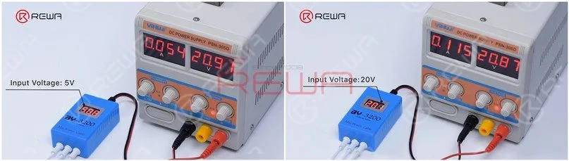
    Plug in the BY-3200 power cable and the input voltage is 20V.

    The current reading on the DC Power Supply stays at 0.047A.

    DC Power Supply

    Unplug the power cable.

    Next, we need to disassemble the MacBook and test.

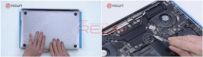
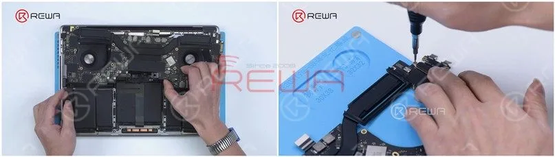
    The MacBook model is A1989. Remove the screws and disconnect the battery connector flex cable.

    How to Fix a MacBook Pro that Won't Turn On

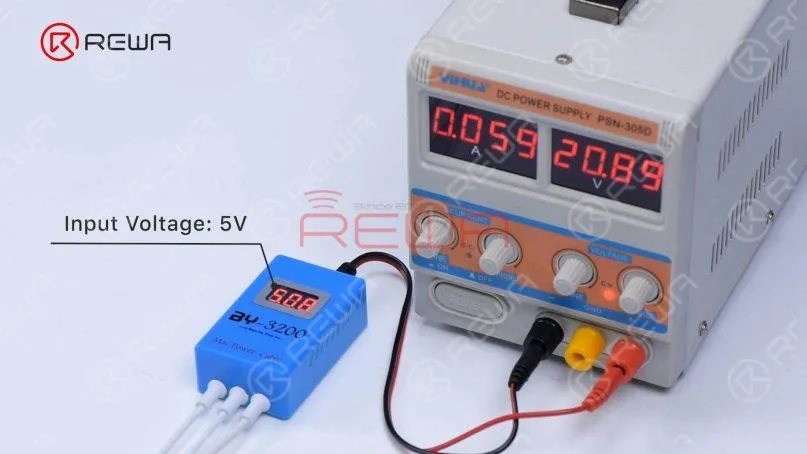
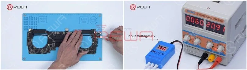
    Plug in the BY-3200 and the input voltage is 5V.

    The current reading on the DC Power Supply stays at 0.059A.

    The power supply of the motherboard is only 5V, which is abnormal.

    How to Fix a MacBook Pro that Won't Turn On

    The normal power supply should be 20V.

    It indicates that the motherboard has malfunctioned.

    Then we remove the motherboard and install the power connector flex cable.

    How to Fix a MacBook Pro that Won't Turn On

    The motherboard number is 820-00850-07.

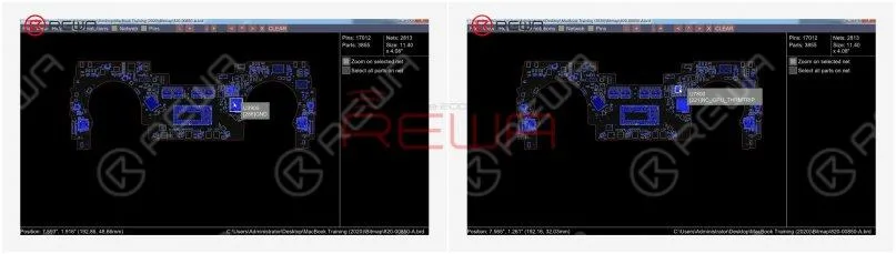
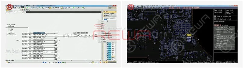
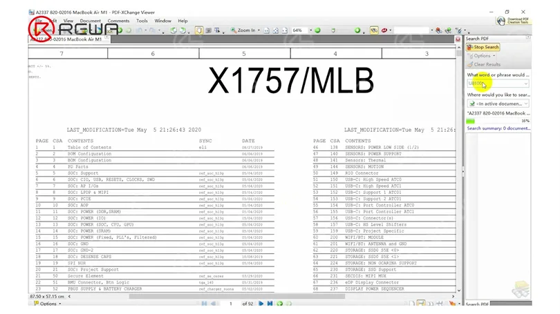
    Open the schematic diagram and bitmap.

    U3900 is the T2 chip. U7800 is the power chip.
    schematic diagram

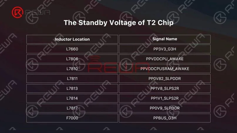
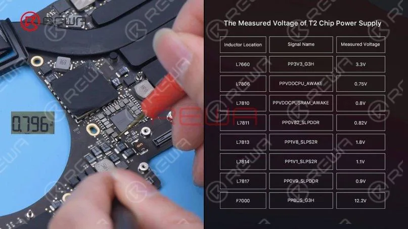
    Measure the standby voltage of the T2 chip, which is supplied by the U7800.

    Find U7800 on the schematic diagram. This table shows the standby voltage of T2 chip.

    standby voltage of T2 Chip

    Plug in the power cable.

    The motherboard current stops at 0.06A and the input voltage is only 5V.
    MacBook motherboard

    Measure the power supply of the motherboard.

    How to Fix a MacBook Pro that Won't Turn On

    The measured voltage values are normal.

    It can be judged that the power supply circuit of the motherboard is good.

    Next, we need to decide if the fault (voltage failing to increase) is caused by T2 chip data problems.

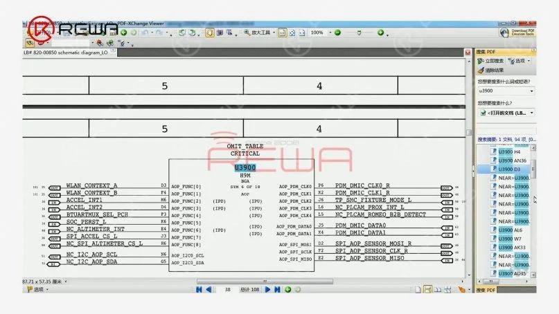
    Find T2 chip on the bitmap and the location name is U3900.

    Search U3900 on the diagram and find the ROM chip for T2.

    How to Fix a MacBook Pro that Won't Turn On

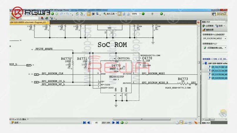
    Copy signal SPI_SOCROM_MISO. Find SoC ROM and the location name is U4770. Find U4770 on bitmap.
    How to Fix a MacBook Pro that Won't Turn On
    How to Fix a MacBook Pro that Won't Turn On

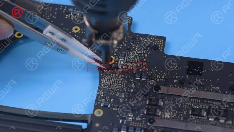
    Find SoC ROM (U4770) on the motherboard. Remove SoC ROM chip with Hot Air Gun at 430℃.
    Hot Air Gun

    Get the BY-T200 and write the new SoC ROM data.

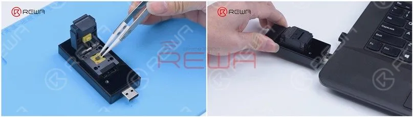
    Attach the chip to the seat of BY-T200. Pin 1 of the chip must align with the red dot on the tool.

    Then connect BY-T200 with the computer.
    MacBook T2 Chip

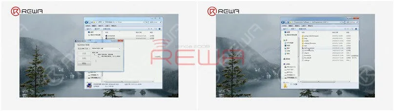
    Install the driver and open AsProgrammer.
    How to Fix a MacBook Pro that Won't Turn On

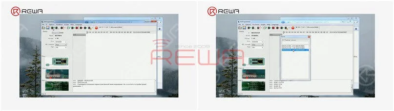
    Click Read ID and select MX25U3235F_1.8V.

    How to Fix a MacBook Pro that Won't Turn On

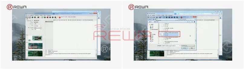
    Click Open file and select A1989 T2 ROM original data.bin.

    How to Fix a MacBook Pro that Won't Turn On

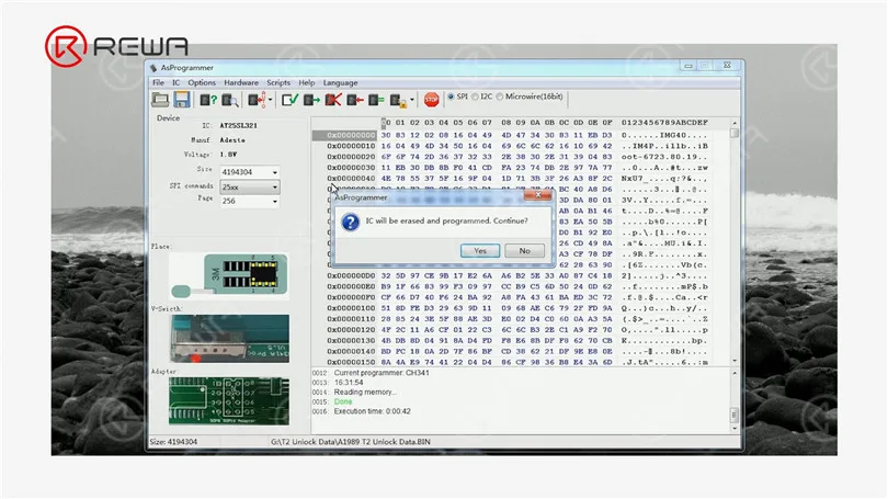
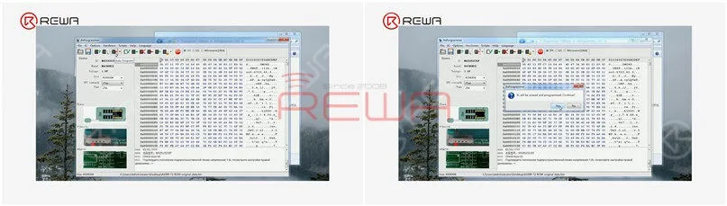
    Click Auto Program and click Yes.

    How to Fix a MacBook Pro that Won't Turn On

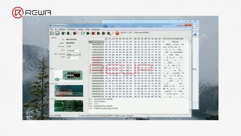
    Data writing has completed.

    data writing

    Unplug BY-T200. Remove the chip. Solder the chip back to the motherboard.
    How to Fix a MacBook Pro that Won't Turn On

    Plug in the power cable. The BY-3200 shows an increase in input voltage from 5V to 20V.

    The current jump on the DC power supply is normal, which indicates that the motherboard is turned on.

    How to Fix a MacBook Pro that Won't Turn On

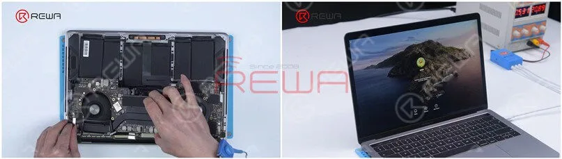
    Disconnect the power cable and install the motherboard.

    Plug in the power cable.

    The MacBook is turned on and can enter the system.
    How to Fix a MacBook Pro that Won't Turn On

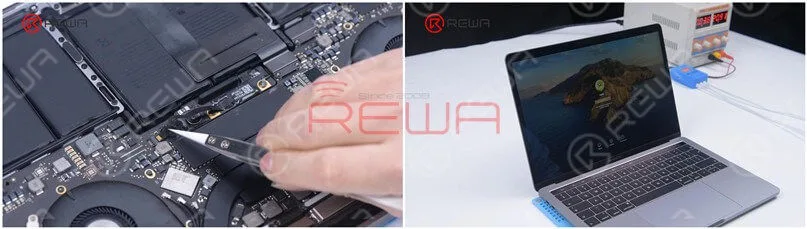
    Lastly, assemble the MacBook.

    Connect the battery flex cable and put the back cover on.

    Plug in the power cable and press the power button.

    The MacBook is turned on and can enter the system. The fault has been cleared.

    How to Fix a MacBook Pro that Won't Turn On

    Summary

    In the first place, we used MacBook BY-3200 power cable to observe the change of boot voltage and current.

    The voltage values related to the boot circuit on the motherboard were found to be normal after measuring.

    To determine whether the fault was caused by data problems, BY-T200 Data Assistant was used to read and write the data of T2 chip ROM.

    After rewriting the ROM data of T2 chip, the MacBook could turn on and enter the system.

    The no power fault has been cleared.

    For more MacBook repair content, please visit our MacBook Repair Guide channel.

    Watch the video below to see how we fix a MacBook Pro that won’t turn on by restoring T2 chip data.

  • MacBook Air 2015 No Backlight Repair

    MacBook Air 2015 No Backlight Repair

    Typically with MacBook Air no backlight problem, the first thing to check is the backlight IC. However, this time we are treating one repair case that is much more complicated. The No Backlight issue is caused by damage of booster diode. Check our blog and see how we confirm the fault by measurement and diagnosis.

    Disassemble MacBook

    Power on. MacBook goes with dark screen. User login interface can be dimly seen.

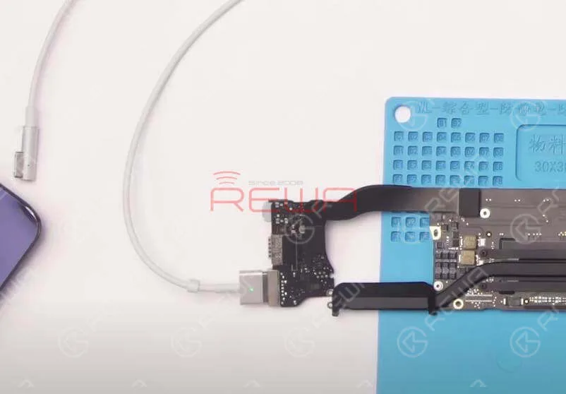
    Remove the lower case and disconnect the battery. Remove the SSD module. Detach the logic board. Detach IO Board as well. Then connect the IO board to the logic board. Confirm the board number of logic board. Detach the display. Then connect the display with logic board. Switch the Multimeter to diode mode. Roll out the maintenance drawing and bitmap.

    MacBook Air 2015 No Backlight Repair

    Run Measurement

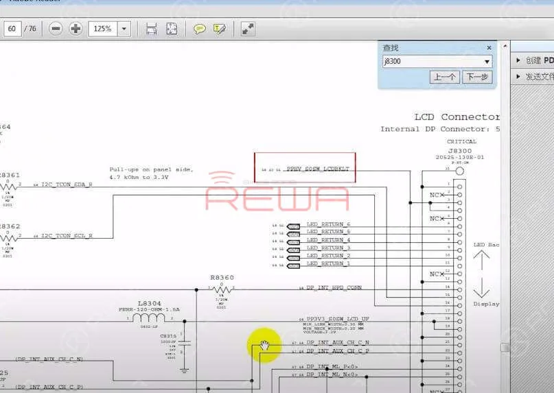
    Locate LCD connector J8300. Check PPHV_S0SW_LCDBKLT. Check relevant circuit of PPHV_S0SW_LCDBKLT. Locate inductor L7701 with maintenance drawing. Measure resistance of L7701. Measured resistance value is 414, normal value.
    MacBook Air 2015 No Backlight Repair

    Switch to voltage mode. Plug in AC adapter and measure the voltage of L7701. The measured voltage value is 8V5. Abnormal voltage value. Normal voltage value should be 25V or so.

    Switch to voltage mode. Plug in AC adapter and measure the voltage of L7701. The measured voltage value is 8V5. Abnormal voltage value. Normal voltage value should be 25V or so.

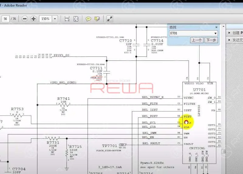
    Disconnect the power supply. Disconnect the display from logic board. Roll out the drawing and confirm the working condition of IC U7701. Locate IC U7701 with bitmap. Locate capacitor C7710 with bitmap. C7710 is connected with U7710 power supply VIN Pin.
    Roll out the drawing and confirm the working condition of IC U7701. Locate IC U7701 with bitmap. Locate capacitor C7710 with bitmap. C7710 is connected with U7710 power supply VIN Pin.

    Switch to resistance mode. Measure the resistance of C7710. Measured resistance value is 428, normal value. Switch to voltage mode. Plug in AC adapter and measure the voltage of C7710. The measured voltage value is 5V, normal value.

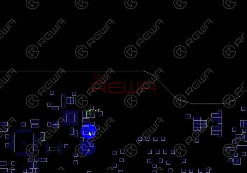
    Locate C7711 with bitmap. C7711 is connected with VDDIO Pin. Measure the voltage of C7711. The measured voltage value is 3V3, normal value. Confirm EN Pins of U7701 with maintenance drawing. Locate R7731 and R7715 with bitmap.

    Warm tips: voltage of EN Pins can be measured with display connected.

    MacBook Air 2015 No Backlight Repair

    Connect the display with logic board. Plug in AC adapter and measure the voltage of R7731. Voltage value of first Pin is 8V5, second Pin 2V8. Normal value.

    Warm tips: voltage value of EN Pins can be read on the meter with display on.

    Confirm PWM Pin of U7701 with maintenance drawing. Locate R7704 with bitmap. Measure the voltage of R7704. The measured voltage value is 3V3, normal value.

    Confirm SCLK Pin of U7701 with maintenance drawing. Locate R7753 with bitmap. Measure the voltage of R7753. The measured voltage value is 3V3, normal value.

    Confirm SDA Pin of U7701 with maintenance drawing. Locate R7757 with bitmap. Measure the voltage of R7757. The measured voltage value is 3V3, normal value.

    Preliminary judgement – U7701 broke down

    Replace U7701

    Disconnect the power supply. Reballing the new U7701 first. Take down the damaged U7701. Then replace with the new U7701. Solder with Hot Air Gun at 430℃.

    Replace U7701

    Wait for the logic board to cool for 5 minutes. Confirm if soldering work has been completed perfectly with Magnifier. Clean with PCB Cleaner.Plug in AC adapter and test if the fault has been cleared. The fault hasn’t been cleared with IC replaced.
    Replace D7701

    Connect the display with logic board. Confirm the relevant circuit of PPHV_S0SW_LCDBKLT with drawing. Locate booster diode D7701 with bitmap. Plug in AC adapter and measure voltage at two ends of D7701. Measured voltage value of End A is 8V5, End K 2V9. Abnormal voltage value for End K. Normal value should be 25V or so.

    Replace D7701

    Disconnect the power supply. Disconnect the display from logic board. Switch to diode mode. Measure resistance at Positive&Negative ends of D7701. Forward direction reads ‘OL’ on the meter, infinite value. Opposite direction reads 176 on the meter. Abnormal resistance value for D7701. We need to replace with a new D7701.

    Replace D7701

    Once replacing has been finished, wait for the logic board to cool for 5 minutes. Clean with PCB Cleaner. Measure resistance of the new D7701. Forward direction reads 166, normal value. Opposite direction reads ‘OL’ on the meter, normal value.

    Measure the resistance between D7701 and grounding. Measured value of End A is 388, End K 531. Normal value for the two ends.

    Test

    Connect the display with logic board and test again.

    Tips: connect with an external USB keyboard, press ‘Alt’ button to power on.

    The screen lights up. Switch to voltage mode. Measure voltage at two ends of D7701 again. Measured voltage value of End A is 8V5, End K 25V. Normal value for the two ends.

    onnect the display with logic board and test again.

    Reassemble And Test

    Disconnect the power supply. Get the screen installed. Get the logic board mounted. Insert the SSD. Plug in AC adapter and test. MacBook goes with normal display.

    Reassemble And Test

    Disconnect the power supply and power off. Get the MacBook full assembled. Run keyboard test and touch test. Repairing completed successfully.

    For detailed operation about MacBook repair, you can also check out   REWA YouTube Channel .

    REWA Academy

    For more tutorials, guides, and premium courses, visit REWA Academy, a platform that encourages the sharing of repair techniques, practical demonstrations, and ideas among electronics repair practitioners. We have developed a number of online and offline repair training courses over the years with the assistance of our teaching staff and R&D team.