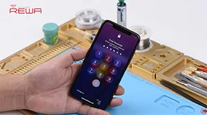
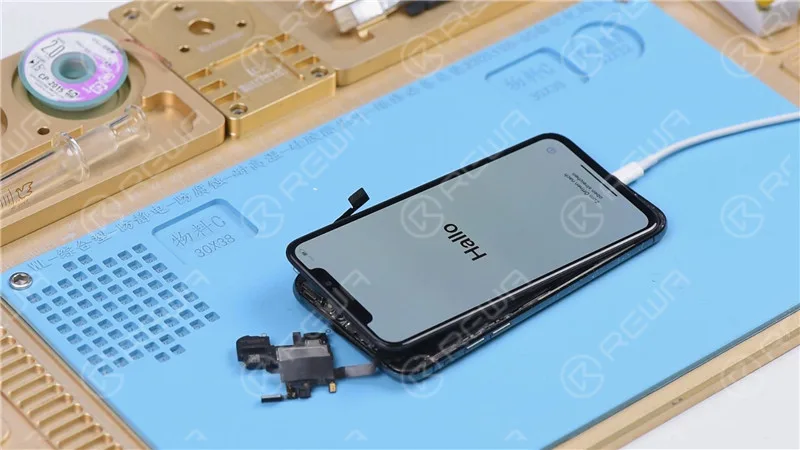
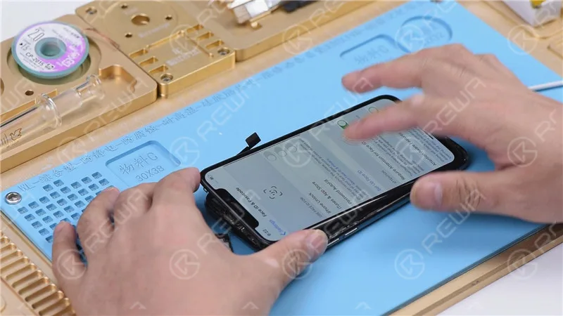
Face ID lets you securely unlock your iPhone, authenticate purchases and sign in to apps all with just a glance. However, due to the vulnerability of the Face ID parts, it can be easily damaged when iPhone X is dropped or during screen replacement, which will result in Face ID failure. Don’t worry. In this video, REWA guides you to fix “Face ID Is Not Available” step by step. Let’s check.
This is also a reminder. Please be careful in your daily use of the phone!
It can be extremely frustrating to find your iPhone stuck on apple logo or iTunes Error 4013. In most cases, this is not a serious issue and a software update can resolve the issue. However, if the software update does not resolve the issue, it may be a hardware issue that requires a more thorough diagnosis and repair.
iPhone Error 4013: Possible Causes
iPhone Error 4013 can occur due to various factors, encompassing both software and hardware components, which contribute to the occurrence of this perplexing error.
Outdated iTunes Version
One of the primary causes of iPhone Error 4013 is an outdated version of iTunes. Since iTunes is crucial for both restoring and updating the device, it is imperative to keep it up to date. A simple and free software update can often resolve this issue, ensuring smooth communication between the iPhone and the computer.
Software Glitches
Random firmware crashes can sometimes lead to iPhone Error 4013. Performing a force restart or hard reset can help overcome these software glitches. By holding down the appropriate buttons, you can initiate a restart that may rectify the error and restore normal functionality.
Hardware Complications
While software issues are common culprits, hardware problems can also trigger iPhone Error 4013. In some cases, sweat or other forms of liquid entering the earpiece can cause a boot loop and lead to this error. Additionally, faulty USB cables, damaged USB ports, or third-party security software can contribute to this frustrating issue.
This blog post will exclusively address hardware problems that can lead to this issue.
Note: Please note that this tutorial utilizes an iPhone X for demonstration purposes, although the method can be applied to most iPhone models.
Cosmetic Inspection of the Motherboard
Before diving into any troubleshooting, it’s essential to ensure the motherboard is in optimal condition. Check for any deformities or water damage that might hinder the repair process.
Identifying the Problem
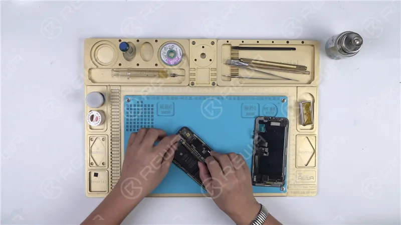
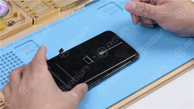
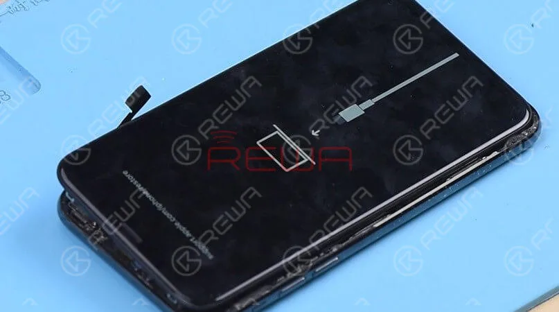
Let’s proceed with the motherboard installation and test it by pressing the power button. However, the phone automatically enters recovery mode, indicating a possible restore failure with the motherboard. As a result, the phone is unable to boot into the system normally.
Restoring the Phone
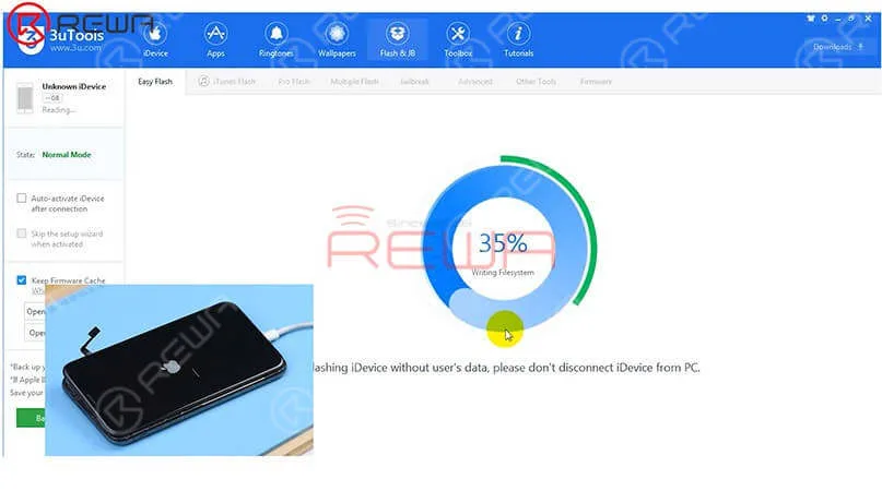
To begin, connect your iPhone X to a computer and initiate the restoration process using 3U Tools. A successful restoration indicates the motherboard is functioning correctly, and your phone can be activated normally.
Diagnosing Further Issues
Successful Restoration
If the phone can be restored successfully and activated, it’s an indication that the motherboard is functioning properly. The issue likely lies elsewhere.
Checking Baseband Info
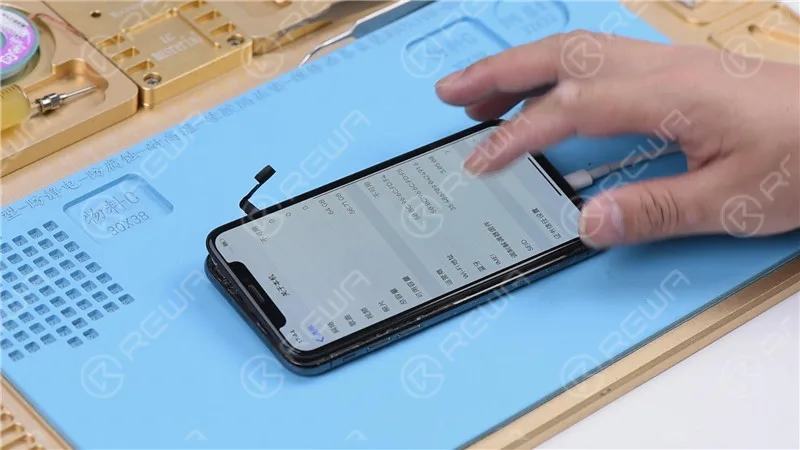
Navigate to Settings>General>About to verify the baseband information, reinforcing the motherboard’s health.
Pinpointing the Issue
Adding Flex Cables: To narrow down the problem, reattach the earpiece speaker and sensor flex cable along with the front camera flex cable, and attempt to turn on the phone.
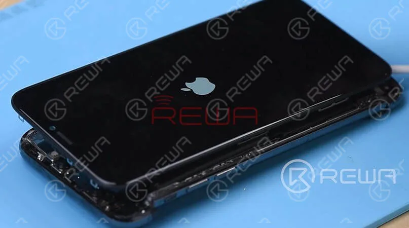
Stuck on Apple Logo: If the phone gets stuck on the Apple logo and restarts, it suggests an issue with the earpiece speaker and sensor flex cable or the front camera flex cable.
Isolating the Problem
Disconnecting the Earpiece Speaker and Sensor Flex Cable: Remove the earpiece speaker and sensor flex cable, then try to power on the phone. If it turns on normally, the issue is indeed related to these components.
Fixing the Flood Illuminator Module
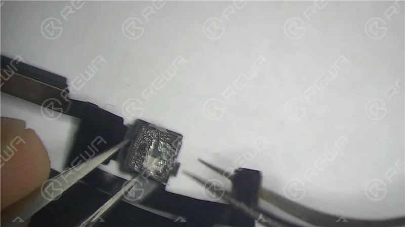
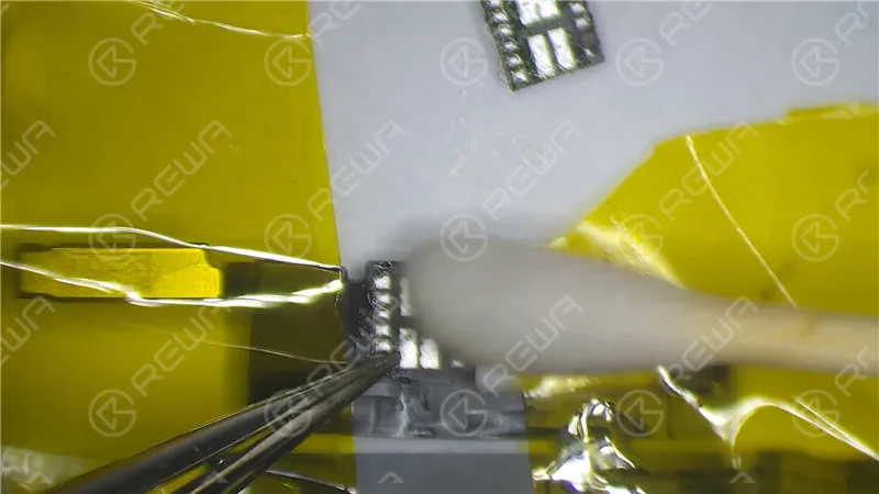
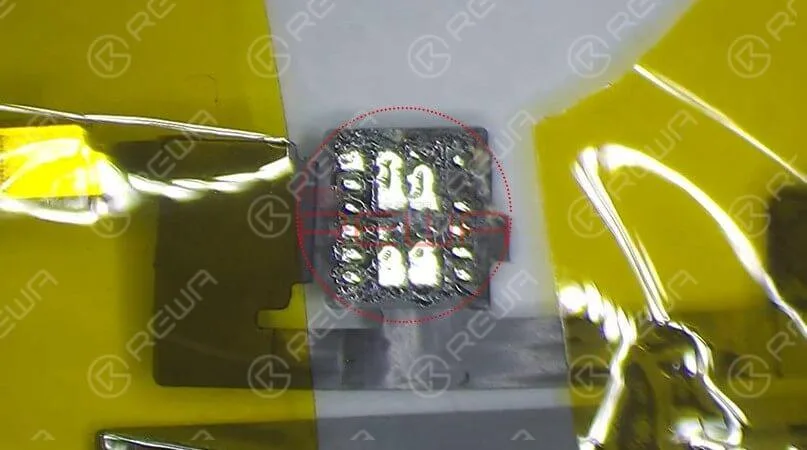
Microscopic Examination: Inspect the Flood illuminator module and identify any mold or corrosion.
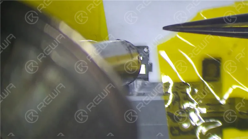
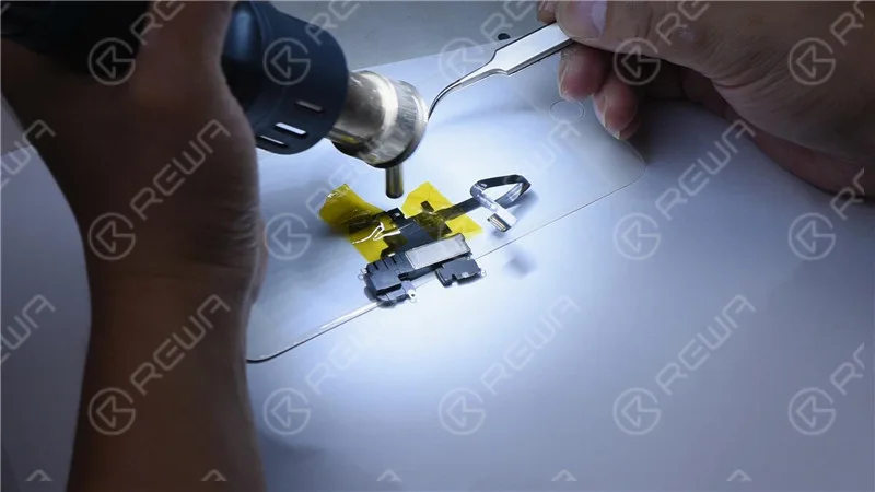
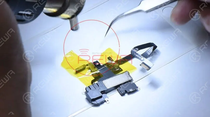
Repairing with High-Temperature Tape: Fix the earpiece speaker and sensor flex cable using high-temperature tape. Heat the affected area with a Hot Air Gun at 320℃ with an air flow of 35. Remove the damaged Flood illuminator module.
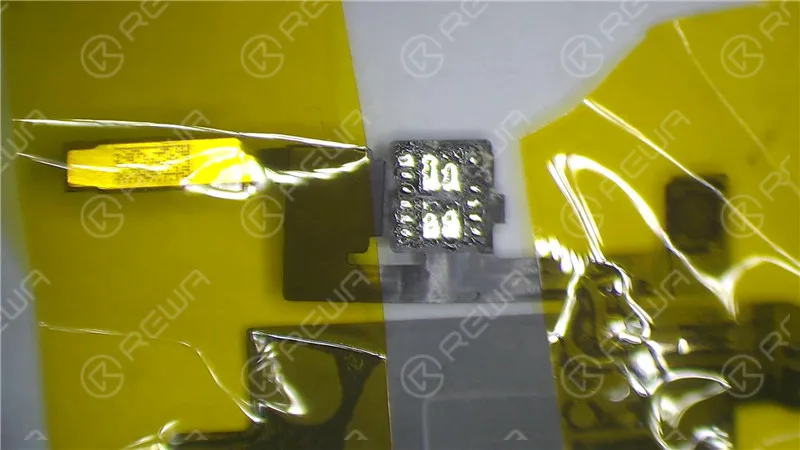
Corroded Bonding Pad: If the bonding pad on the Flood illuminator module is severely corroded, apply paste flux, clean with a soldering iron at 360℃, and reapply medium-temp solder paste. Clean with PCB Cleaner afterward.
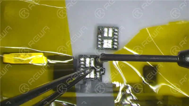
Reassembly: Reassemble the Flood illuminator module, applying paste flux and soldering it in place with a Hot Air Gun at 320℃.
Wait for 2 Minutes: Allow the repaired components to settle for two minutes.
Testing and Restoring
Reconnection: Reinstall the earpiece speaker and sensor flex cable, connect the battery, and power on the phone.
Restoring with Components Connected: Since the flex cables were not connected during the previous restoration, restore the iPhone X with both cables connected to ensure Face ID functionality.
Final Verification
Entering DFU Mode: Place the phone in DFU mode and connect it to the computer.
Restoration: Use 3U Tools or similar software to restore the phone. If it completes successfully, and the phone boots into the system and allows for Face ID setup, the issue has been resolved.
Video Guide to Fix iphone stuck on apple logo
Conclusion
In this comprehensive guide, we have walked through the troubleshooting and repair process for an iPhone X stuck on the Apple logo with iTunes Error 4013. By methodically evaluating each component, from the motherboard to the earpiece speaker and sensor flex cable, we’ve successfully identified and fixed the issue, allowing the phone to function normally once again. For more in-depth repair knowledge, consider visiting REWA Academy.
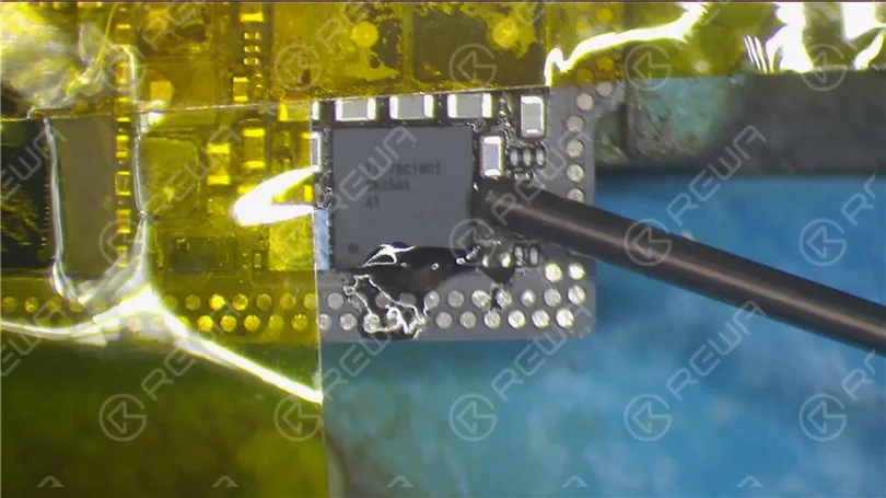
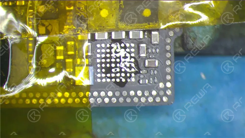
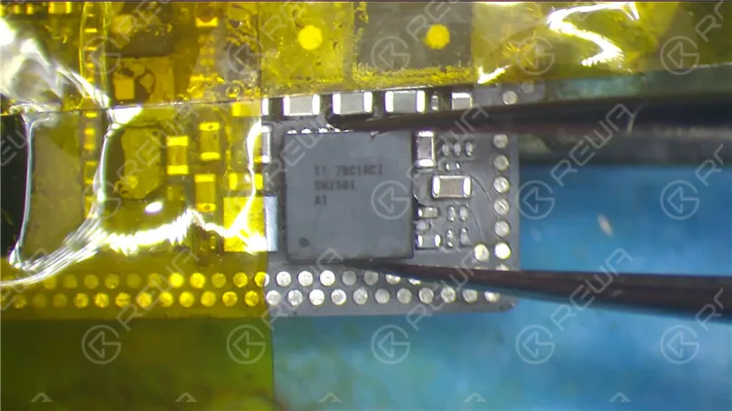
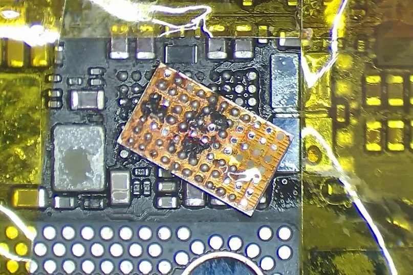
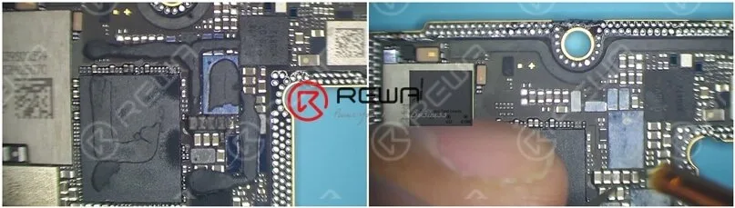
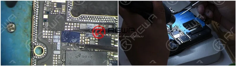
Hello guys, today we will walk you through repair tricks for desoldering&soldering of iPhone X charging IC.
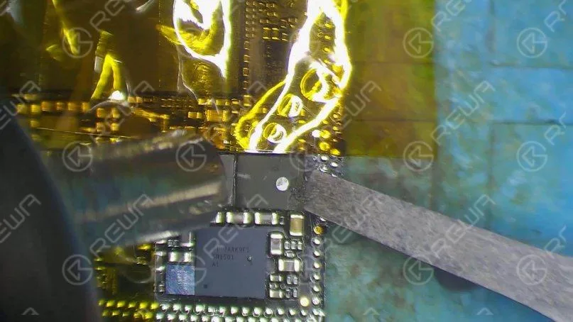
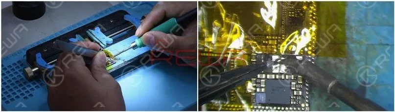
First, stick high-temperature tape on components around the charging IC to protect them from pseudo soldering/bridging during the operation.
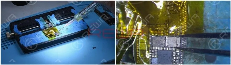
Then apply some paste flux around the charging IC.
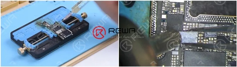
Set temperature of the QUICK 990 AD Vertical Wind Hot Air Gun at 330℃, air flow 3. Keep the hot air gun at 5mm-10mm height from the charging IC.
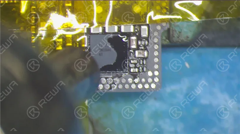
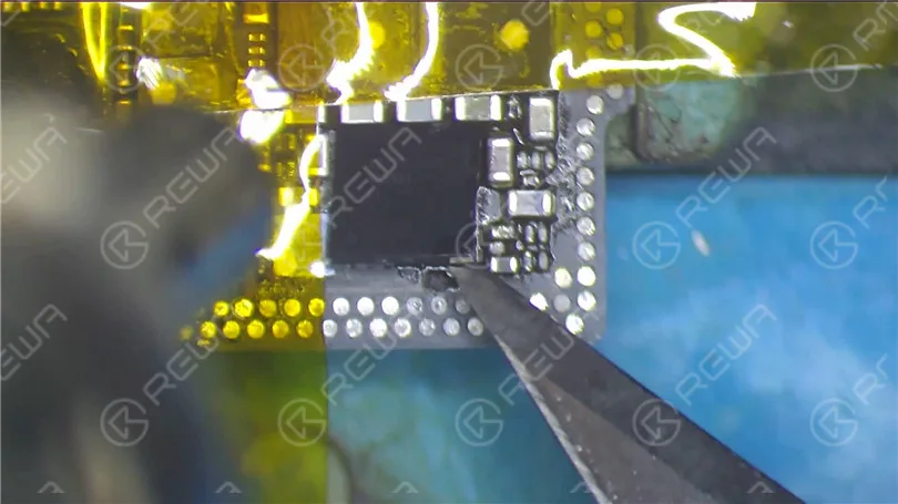
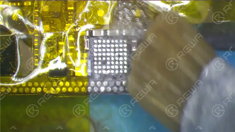
Heat for around 15s-20s, then pry up the charging IC. Tips: control the force applied when prying up the IC. Rough operations might damage the chip or the bonding pad.
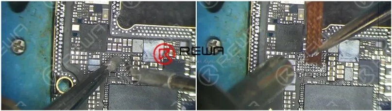
Continue to apply some medium-temp solder paste to the bonding pad. Heat with the QUICK 990 AD Vertical Wind Hot Air Gun at 280℃, air flow 3.
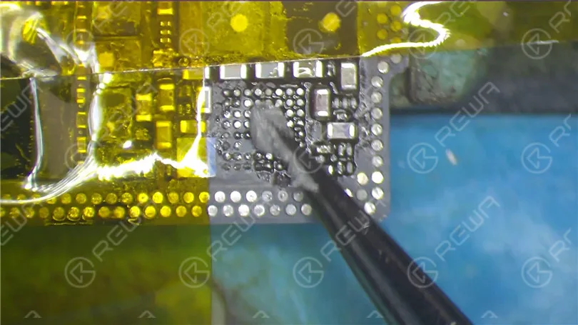
Meantime, clean solder joints on the bonding pad with Soldering Iron at 360℃. Once done, clean the pad thoroughly with rosin soaked solder wick.
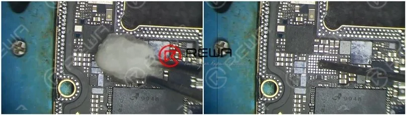
Also, be careful with your operation here. Rough operations might result in pseudo soldering/bridging of components around
Clean with PCB Cleaner afterward.
Now we need to clean solder joints on the backside of the charging IC.
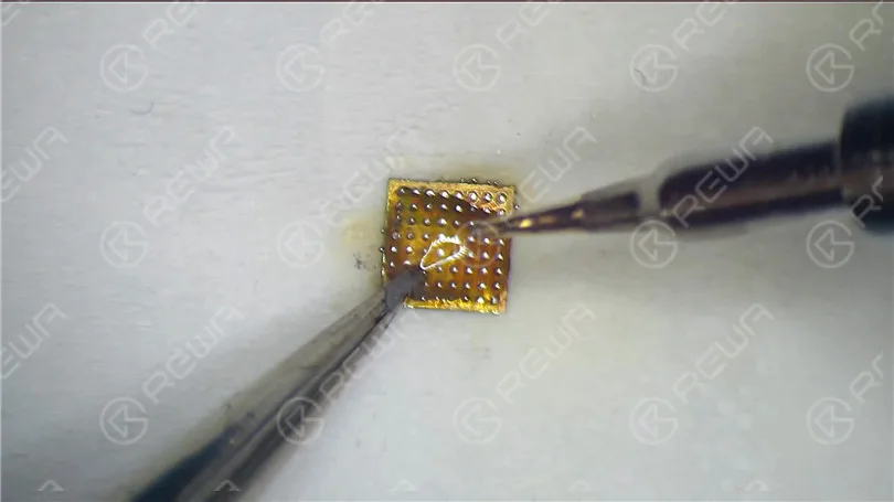
Apply some medium-temp solder paste to the bonding pad on the backside. Clean the pad with Soldering Iron at 360℃.
Also, you can apply some paste flux for better cleaning.
Once done, clean with PCB Cleaner. Tips: don’t be too strict with solder joints on the pad. You can keep several solder joints for the sake of perfect reballing afterwards.
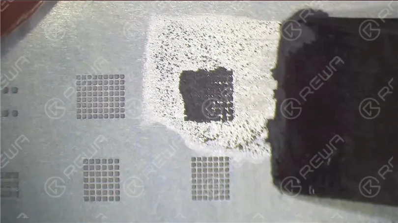
Let’s move on to the reballing process. Get the BGA Reballing Stencil in position. Apply some medium-temp solder paste with BGA Scraper.
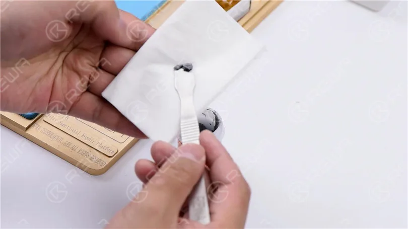
Then apply the solder paste to a facial tissue. This is to dry the solder paste by wrapping in the facial tissue.
So that the solder paste can be well prepared for reballing. Wettish solder paste might result in bridging during reballing. Continue to smear medium-temp solder paste evenly on the stencil. Wipe out needless solder paste with lint-free wiping cloth.
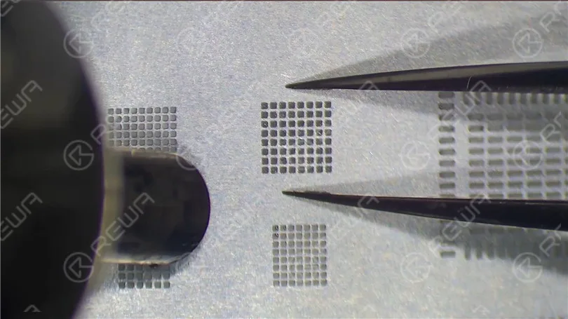
Apply pressure to the BGA Reballing Stencil with tweezers. Heat with the QUICK 990 AD Vertical Wind Hot Air Gun at 300℃, air flow 3. So that all solder balls can solidify completely.
Tips: when heating, the hot air gun should approach from far to near from edges to the center.
Concentrated heating might get the stencil deformed. The shaping-up process of solder balls might also be affected.
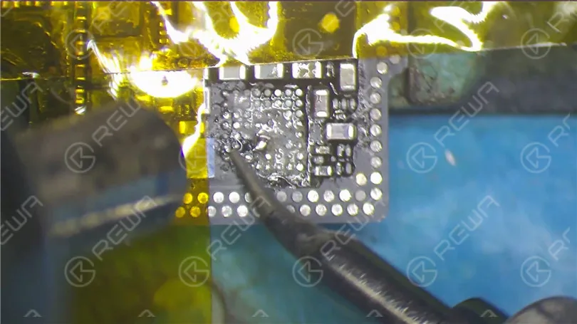
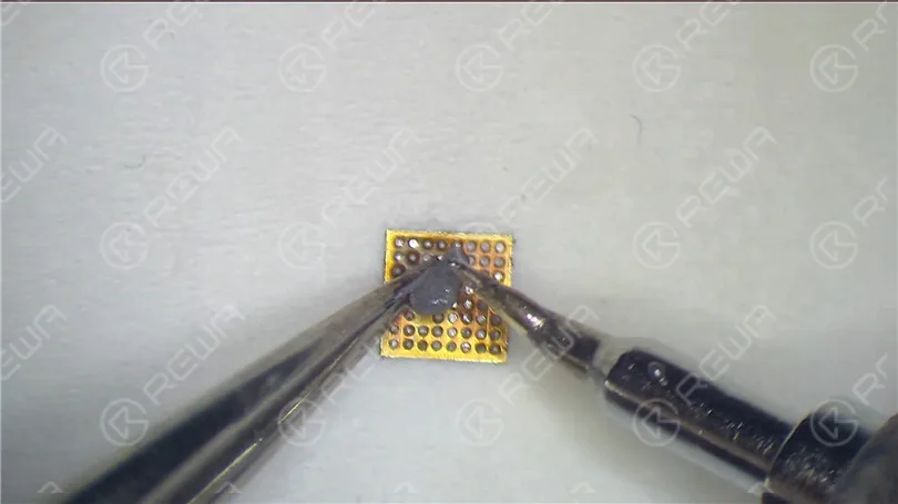
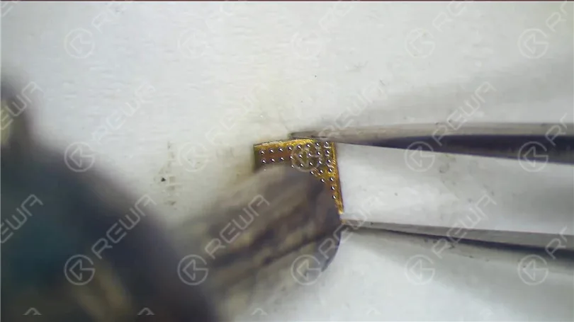
Once done, cool for 1 minute. Clean with PCB Cleaner afterwards. Separate the chip from the stencil with tweezers gently. Then clamp the chip with tweezers.
Heat again with the QUICK 990 AD Vertical Wind Hot Air Gun at 300℃, air flow 3. This is to ensure the perfect formation of solder balls.
Now we can solder the charging IC. Apply some paste flux to the bonding pad.
Get the charging IC in the right position.
Do not place it in the wrong direction. Solder with the QUICK 990 AD Vertical Wind Hot Air Gun at 330℃, air flow 2. 15s-20s later, with the IC sinking and paste flux overflowing.
Continue heating for like 5 seconds. Once done, clean with PCB Cleaner.
Feel free to visit REWA Academy to study more phone repair techniques and skills.
iPhone gets stuck on the Apple logo, which usually means that there is a problem with the operating system or hardware of the phone. Check out our video today and we will show you how to diagnose and fix the problem step by step.
Today we will talk about how to replace iPhone X SIM card reader.
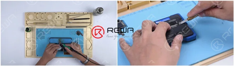
The SIM card reader of iPhone X is soldered with medium-temperature tin, while the middle layer of the motherboard adopts low-temperature tin. Hence we advise you to separate the motherboard before removing the SIM card reader. There are other ICs on the SIM card reader. Besides, a plastic part is also in the middle of the SIM card reader.
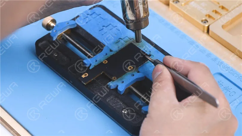
While disassembling and soldering, we need to heat it with rotational air and control the temperature. Attach the motherboard to the PCB Holder. Heat it with Hot Air Gun 240℃ and airflow 7. Tear off the sticker on the back of the motherboard.
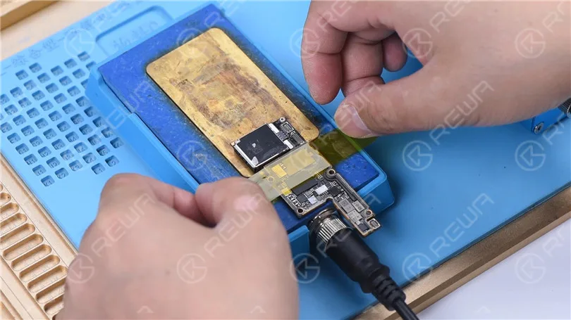
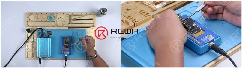
Put the motherboard on the Heating Platform. We only need to heat the SIM card reader part. Fix the motherboard with high-temperature adhesive. Set the temperature of the Heating Platform to 200℃. Heat the edge of the SIM card reader with Hot Air Gun 280℃ and airflow 7.
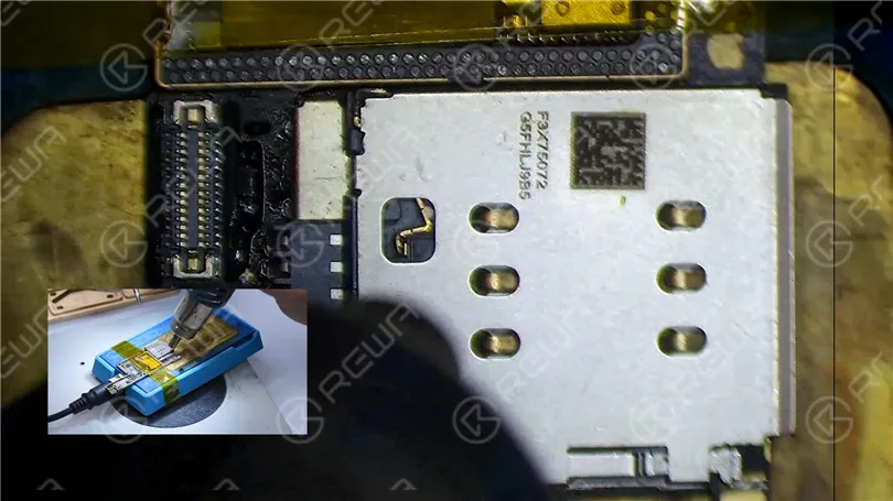
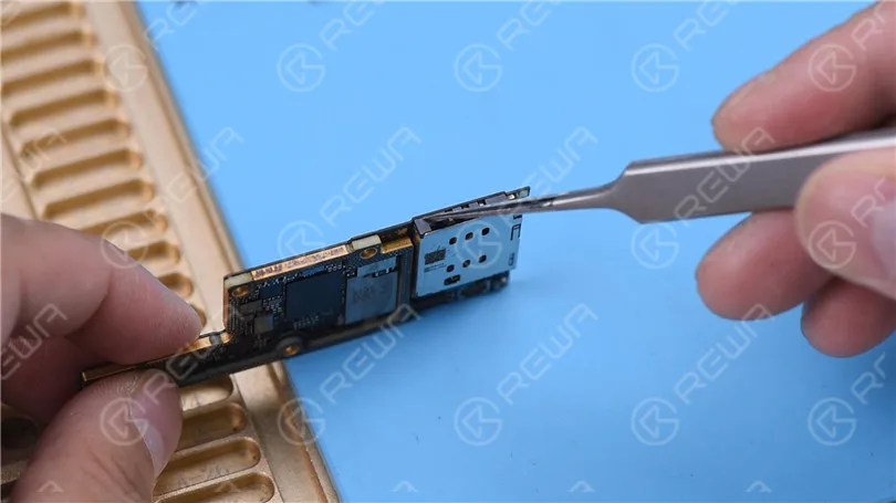
Stir the SIM card reader with tweezers while heating. Remove the SIM card reader when it becomes loose. Please be noted that we need to pick up the SIM card reader in a vertical manner. To avoid damage or malposition of components under the SIM card reader, please do not pry with tweezers. Next, we replace the old SIM card reader with a new one. Apply some Paste Flux to the bonding pad of the SIM card reader. Put the new SIM card reader in position. Keep heating it on the 200℃ Heating Platform. Heat the edge of the SIM card reader evenly with Hot Air Gun 280℃ and airflow 7. Press the SIM card reader gently while heating. Make sure that the SIM card reader is pressing against the PCB.
Turn off the power. Cool the motherboard. Check the SIM card reader soldering. The SIM card reader is pressing against the PCB. Every soldering spot has no pseudo soldering. Solder it again with Soldering Iron if pseudo soldering happens.
Please set the temperature of the Hot Air Gun according to the environment and device brand. The temperature in this article is only for reference.
Please visit REWA Academy to study more iPhone repair knowledge.
Frozen or Touchscreen unresponsive is one of the most commonly seen cases in iPhone repair. Generally speaking, there are two different causes for iPhone x touch screen unresponsive. Malfunction of rails or components on the motherboard. Or touch failure caused by malfunction of the screen, which can be easily fixed by replacing with a new display assembly.
Today, we are teaching you how to rule out and get the problem fixed by starting with simple, then complex.
We don’t know where the problem lies. On screen? Or on the motherboard? So here we use a simple way to make a preliminary judgment first. Replace with a new undamaged screen! If it works fine on this phone board, we can confirm that the problem is related to the screen. As iPhone X screen digitizer assembly is expensive, it’s not that cost-effective for customers to change a new one. So let’s try to fix it. Cosmetic inspection goes first!
We can see that the touch flex cable is not fractured, and the touch connector also looks fine. There is nothing unusual on the bonding area between the touch flex cable and the display flex cable. Judging by this, the fault is probably caused by the touch IC or the screen itself. So let’s start with the touch IC.
Stick High-temperature Tape around the touch IC. Then place a thermal insulation gasket under the touch IC. Heat with the Hot Air Gun to remove black adhesive around the touch IC.
Once done, pry up the touch IC. And then clean the bonding pad. Once finished, apply some Paste Flux to the bonding pad. Get a new touch IC in position and solder with Hot Air Gun. Clean with PCB Cleaner after soldering.
Now we can assemble the phone and test if the touch screen of the phone is back to normal. Here is the detailed video for your reference. PLUS: with our unique teaching system, REWA offline training course can help technicians improve their repair skills by mastering repair thoughts and repair techniques. Our training course for April is in full swing at Czech right now. No more hesitating. Enroll now !
iPhone water damage has always been a frustrating and difficult issue for repair technicians. Things can also be much more difficult when it comes with iPhone X/XS/XS Max. What you usually do with iPhone water damage repair? Got your unique repair thoughts? Well, don’t panic! Our iPhone X water damage repair blog today shall definitely enlighten you.
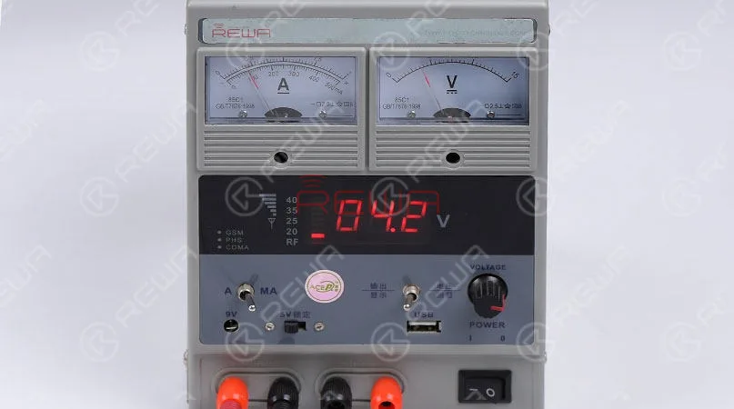
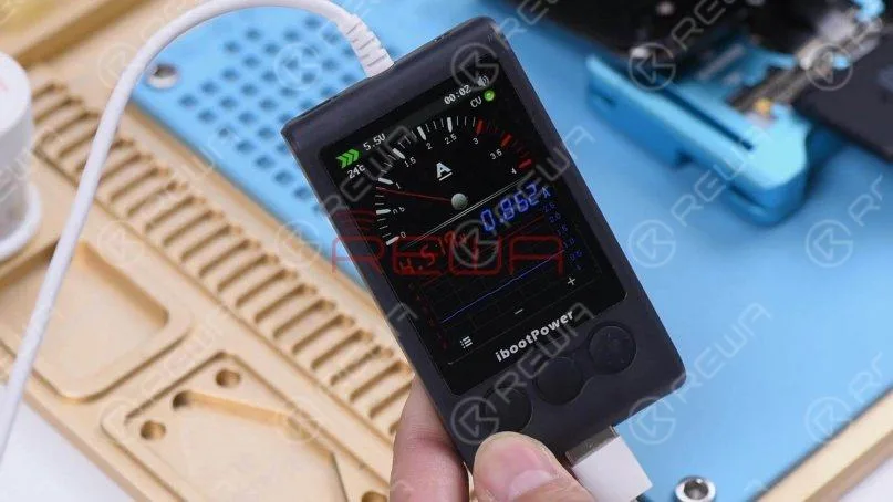
Press the power button to turn on the phone but there is no response at all. Let’s take apart the phone and remove the display assembly first. Connect the battery connector with the DC Power Supply. Current reading on the ammeter jumps to 100mA and then stays still, which is abnormal.
Step 1: Motherboard Separating
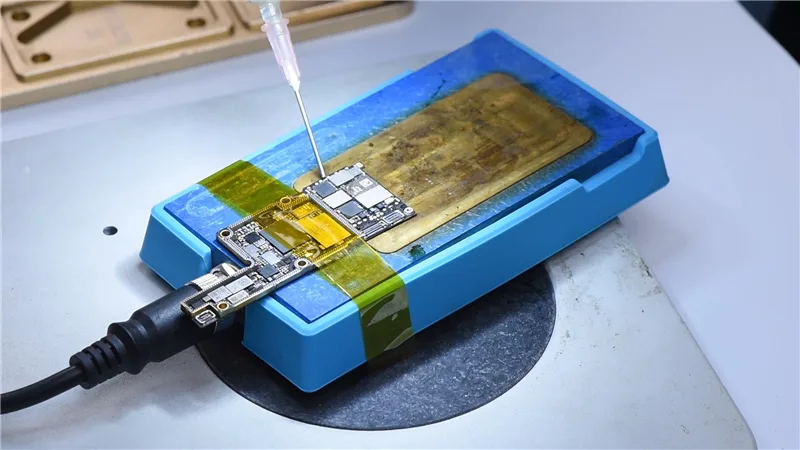
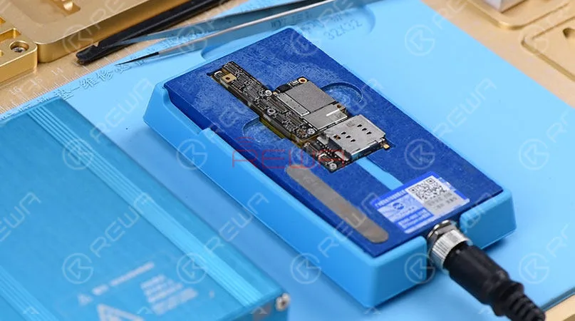
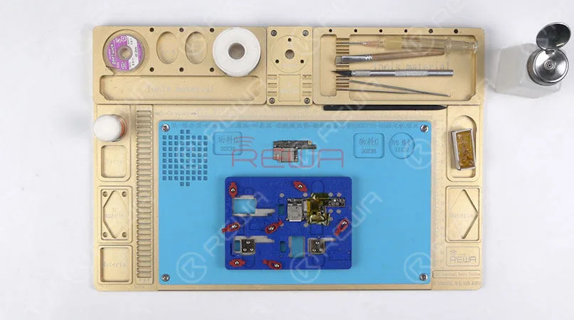
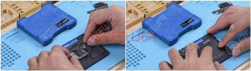
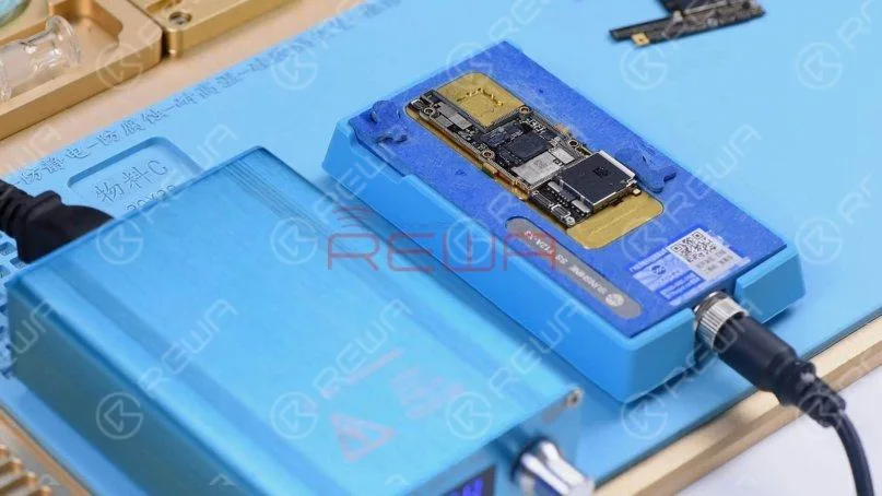
Place the motherboard on the specialized Heating Platform. With temperature of the platform reaching the set temperature. Detach the upper layer and the lower layer from the platform with tweezers. The specialized Heating Platform is perfect for iPhone X motherboard separating.
Step 2: Fault Finding
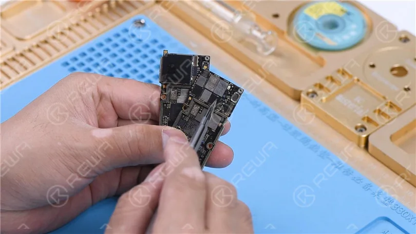
Check the two layers under the Microscope, and we can see nothing goes wrong with the upper layer. Yet areas on the lower layer bear obvious signs of water damage. Let’s clean the motherboard first.
Step 3: Fault Analyzing
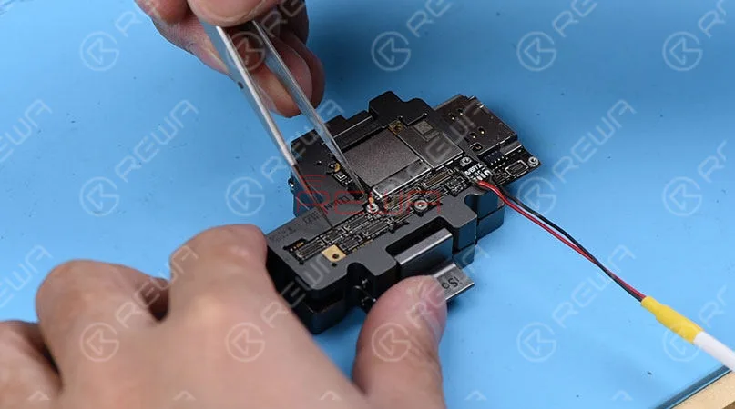
Attach the upper layer and the lower layer to the test fixture and get the phone powered on with tweezers. Current reading on the ammeter jumps to 100mA and then stays still, which is abnormal. Connect the battery connector on the upper layer and powered on. Current reading on the ammeter is normal. Judging by this, the upper layer has nothing to do with the won’t turn on issue and the fault is probably related to the lower layer. So our next move is to further measure the lower layer.
Step 4: Fault Confirming
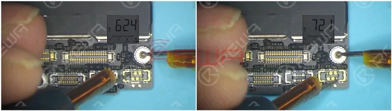
Run diode mode measurement of capacitors around the moldy IC U3400, and there is no short-circuit problem around U3400. Continue to run diode mode measurement of the third space PCB. The measured value of Pin S30 is 40, which is abnormal. Since Pin S30 is connected directly to Pin L4 of U3400, the fault is probably related to U3400. So the next thing we do is to check U3400. First, remove U3400 with Hot Air Gun. We can see that U3400 and its bonding pad have mildewed severely. Therefore, we need to replace it with a new IC.
Step 5: Fault Clearing
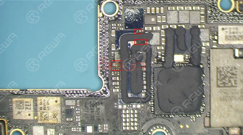
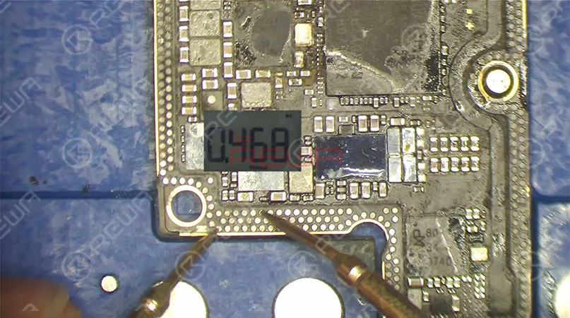
When cleaning the bonding pad, we find that three components around U3400 have been subjected to different degrees of corrosion. We need to remove the three components one by one and solder new components to corresponding positions. After that, we can move on to IC soldering. Once done, wait for the lower layer to cool for 5 minutes. Again, run diode mode measurement of Pin S30 on the third space PCB. The measured value is 468, which is normal now.
Step 6: Test
Now, attach the upper layer and the lower layer to the test fixture. Current reading on the ammeter is normal this time and the phone turns on normally.
Step 7: Reballing
In this step we will use a very useful tool, known as iPhone X specialized reballing mold. It can help us complete the reballing process perfectly.
Step 8: Motherboard Recombining
With the help of iPhone X specialized Heating Platform, the motherboard recombining process is very easy and efficient. Wait for the motherboard to cool for 10 minutes.
Step 9: Assemble & Test
Now we can assemble the phone and test. Press the power button to turn on the phone. The phone turns on normally. Fault cleared. Warm tips: get the phone full assembled after confirmation of fault clearance. iPhone X won’t turn on caused by water damage fixed perfectly.
For more iPhone X water damaged troubleshooting details, please visit here: REWA ONLINE SHOP IS OPEN, EQUIPPED WITH ALL TOOLS USED IN THE BLOG, READY TO POWER YOUR REPAIR BUSINESS?
Wireless charging technology has been prevalent in today’s smartphones. Wireless charging appears so convenient and effortless that more and more people are eager to try it and use it in their daily life. However, the reality is not always as smooth as expected. You place the iPhone on the charging pad, but nothing happens. In this article, we will share how to fix an iPhone X that is not wirelessly charging.
1. Motherboard Check
First of all, run a cosmetic inspection of the motherboard. The motherboard is not deformed or water-damaged.
2. Assemble and Test
In the next place, assemble the phone and test. Press the power button to turn on the phone. The phone turns on normally.
Plug in the charging cable. The phone can be charged with the charging cable. Place the phone on a wireless charger. The phone cannot be wirelessly charged.
We need to focus on wireless charging relevant circuits.
3. Run Diode Mode Measurement of the Wireless Charging Connector
Take apart the phone and take out the motherboard. Remove the dust-proof sponge covering the board first. Then run diode mode measurement of the wireless charging connector. The measured value is normal, which indicates that wireless charging relevant circuits on the bonding pad are normal. We need to move on to wireless charging relevant circuits on the lower layer.
4. Motherboard Separation
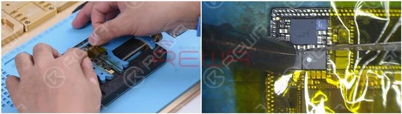
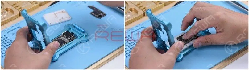
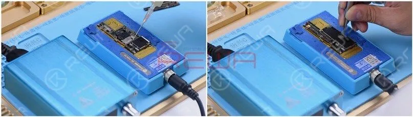
The first thing we do is to separate the upper layer from the lower layer. Place the motherboard on the heating platform and fit a screw into the screw hole on the motherboard. So we can take down the upper layer efficiently afterward.
Heat the motherboard for 2 minutes on the heating platform at 165℃. After heating, take down the upper layer with tweezers and then the lower layer.
5. Lower Layer Inspection
Run a cosmetic inspection of the lower layer. Nothing goes wrong. Run diode mode measurement of capacitors around the wireless charging IC. Judging by the measured value, there is no short-circuited condition. Continue measuring diodes around the wireless charging IC. The measured value is also normal.
6. Wireless Charging IC Replacement
Let’s try to replace with a new wireless charging IC and see how it works.Attach the lower layer to the PCB holder and apply some paste flux to the wireless charging IC. Heat with QUICK 990 AD Hot Air Gun at 360℃, air flow 3 for about 1 minute. Take down the wireless charging IC from the board with tweezers.
Continue to apply some medium-temp solder paste to the bonding pad. Heat with soldering iron at 365℃ to clean the bonding pad. Once done, heat with Hot Air Gun at 360℃, air flow 3 to clean the bonding pad with rosin soaked solder wick.
Clean with PCB cleaner afterward and apply some paste flux to the bonding pad.
Get a new wireless charging IC in the right position and solder with QUICK 990 AD Hot Air Gun at 360℃, air flow 3.
7. Motherboard Restoration
The next thing we need to do is to solder the two layers together. Clean the bonding pad before soldering. Once done, get the bonding pad reballed.
Once completed, place the lower layer on the heating platform. Apply some BGA paste flux to the bonding pad and get the upper layer in the right position. Heat for 2 minutes on the heating platform at 165℃.
Now we can assemble the phone and test.
8. Wireless Charging Not Working On iPhone X Has Been Successfully Fixed
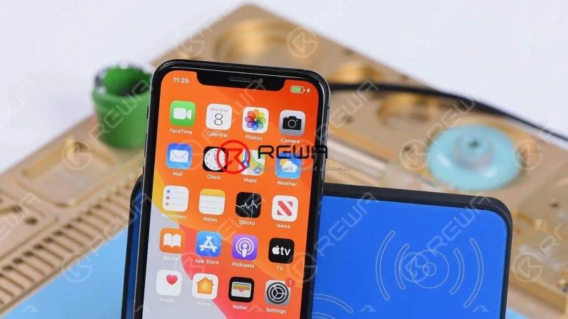
Get the motherboard installed and display assembly connected. Press the power button to turn on the phone. The phone turns on normally.Place the phone on a wireless charger and the phone can be wirelessly charged.
Conclusion
iPhone X wireless charging is not working. Plug in the charging cable and test. The phone can be charged with the charging cable. So we need to focus on wireless charging relevant circuits. Check wireless charging relevant components around the wireless charging IC. All going well. Try to replace with a new wireless charging IC and the problem is fixed.If you are looking for more in-depth content and want to study systematically, please feel free to visit REWA academy.
Our repair case today is about repairing an iPhone X that won’t charge but with the lightning bolt showing up.
First of all, let’s get the motherboard installed and test. The phone turns on normally. Plug the charging cable and the lightning bolt shows up. However, there is no charging current on the ammeter. Judging by this, the motherboard can detect the power adapter whereas the phone won’t charge.
Since the housing, the battery, and the charging port flex cable used for the test are known-good parts, we need to focus on the charging circuit on the motherboard. The first thing we need to do is to separate the upper layer from the lower layer. Place the motherboard on the heating platform and fit a screw into the screw hole on the motherboard. So we can take down the upper layer efficiently afterward. Heat the motherboard for 2 minutes on the heating platform at 165℃.
Remove the upper layer and lower layer with tweezers.
Run diode mode measurement of Pin 2 and Pin 3 on the battery connector J3200. The measured value is normal.
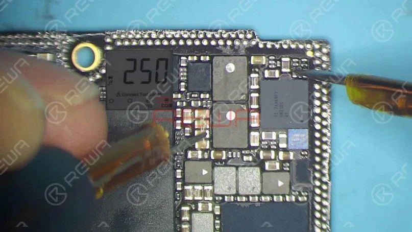
Continue measuring TIGRIS_LX between charging IC U3300 and Q3350. The measured value is 250, which is abnormal. The normal value should be 0. Judging by the measured value, TIGRIS_LX has open-circuited.
L3341 and L3340 are connected in series on the circuit. The open-circuited condition indicates that the two inductors might have been pseudo soldered or damaged. We need to replace the two damaged inductors with new inductors. Attach the upper layer to the PCB holder and stick high-temperature tape on components around. Heat with QUICK 990AD Hot Air Gun at 300℃ and airflow 3. Remove black adhesive around the two inductors.
Once done, apply some paste flux to the two inductors. Heat with Quick 990AD Hot Air Gun at 360℃ and airflow 3.
Pry up the two inductors carefully with the pry knife.
Continue to apply some medium-temp solder paste to the two bonding pads. Tin the two bonding pads with Soldering Iron at 365℃. Then clean black adhesive on the bonding pad.
Continue to apply some paste flux to the two bonding pads. Get the two inductors in the right position, and solder with QUICK 990AD Hot Air Gun at 360℃ and airflow 3.
Clean with PCB cleaner afterward. Again, let’s run diode mode measurement of TIGRIS_LX between U3300 and Q3350. The measured value is 0, which is normal.
Now we need to attach the upper layer and the lower layer to the testing fixture and test. Firstly, clean the bonding pad.
Then attach the upper layer and the lower layer to the testing fixture.
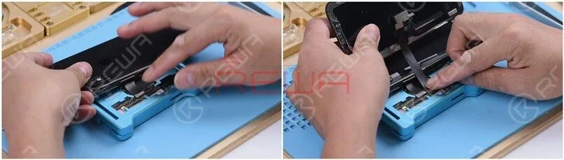
Get the charging port flex cable connected. Then get the screen and the battery connected.
Plug the charging cable. The charging current on the ammeter is 860mA, which indicates that the phone can be normally charged.
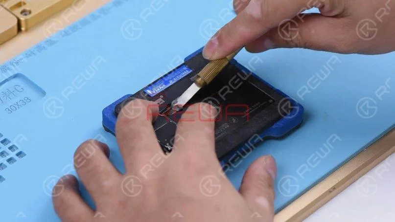
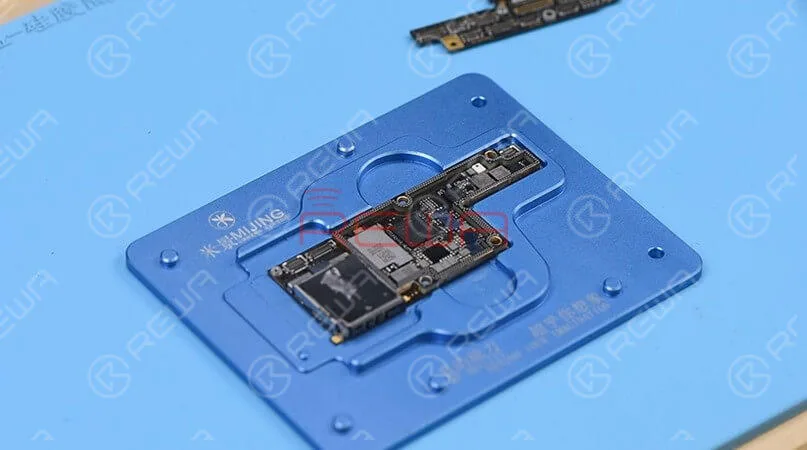
The next thing we need to do is to solder the two layers together. We need to get the lower layer reballed first. Put the lower layer into the reballing moldand get the BGA Reballing Stencil in position.
Place the mold onto the base. The stencil is tightly attached to the lower layer because of the magnetic structure of the base. Then we smear some low-temp solder paste on the stencil and wipe off excess solder paste with a lint-free wipe.
After reballing, take the mold down from the base and remove the reballing stencil. Heat the lower layer on the heating platform at 165℃. Once solder balls have shaped up completely, power off the heating platform.
Cool for 5 minutes. Apply some BGA Paste Flux to the bonding pad and get the upper layer in position. Then power on the heating platform. With the temperature reaching 165℃, continue heating for 2 minutes.
Turn the power off and cool for 5 minutes. Then take down the motherboard from the heating platform. Please check carefully to make sure that the two layers have been soldered together perfectly. Now we can assemble the phone and test. Get the motherboard installed and display assembly connected. Plug the charging cable. The lightning bolt shows up on the screen. The charging current on the ammeter is also normal. The fault is cleared.
Conclusion
The lightning bolt shows up on the iPhone X screen while there is no charging current on the ammeter. Check the charging circuit on the motherboard and one rail has open-circuited. Replace the two inductors on the rail and the problem is fixed.
If you are looking for more in-depth content and want to study systematically, please feel free to visit our academy.
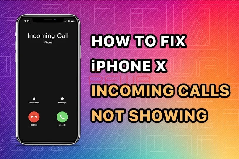
Some iPhone users may encounter such a problem, when the phone screen is turned off, we cannot receive the call.
Right now, there are few solutions to fix iPhone not responding in sleep mode when getting incoming calls.
The general repair process of a repair technician is to take out the motherboard, check PMU and baseband CPU, and then replace or re-solder the faulty component.
The whole repair process is complicated and difficult.
Now REWA LAB will show you a brand new ‘signal borrowing’ solution to fix this problem quickly and efficiently.
Problem
Here we have an iPhone X not responding in sleep mode when getting incoming calls. When we were trying to test the Sounds&Haptics function, we found all going well.
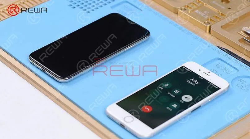
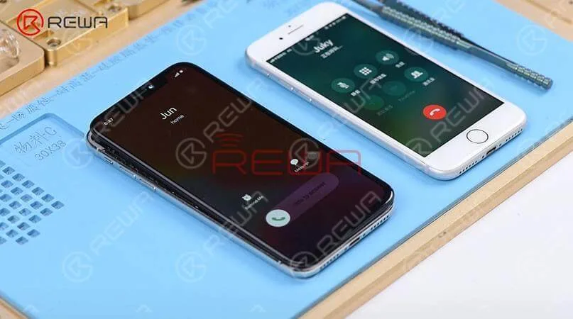
With the screen on, we placed a call to the phone using a known-good phone. And the decline and answer buttons appear on the screen.
However, if we turned the screen off, the phone is not responding at all. Then we pressed the power button to turn the screen on and we can see the incoming calls showing on display.
Diagnosis
Judging by this, we can infer that relevant circuits of the baseband wake signal might have malfunctioned. So we took apart the phone, disconnected the battery, removed the display assembly, and took out the motherboard.
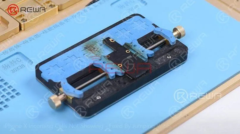
The following step is to attach the motherboard to the PCB Holder and then heat with Hot Air Gun at 200℃, airflow 3 to tear off the heat dissipation sticker on the backside of the motherboard.
Confirm the Signal Fault Location
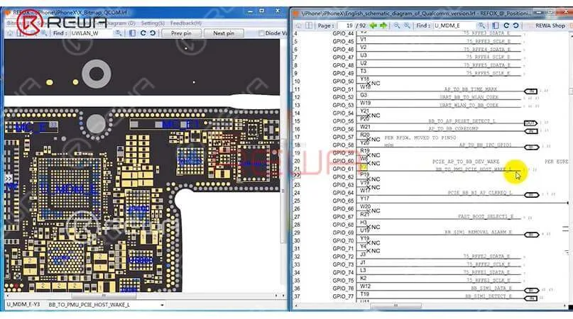
We can open the bitmap software in Refox and locate BB_TO_PMU_PCIE_HOST_WAKE_L first.
Since relevant circuits of the wake signal might have malfunctioned, so we can try to borrow the wake signal from WiFi relevant circuits.
Borrow Signal by Jumping a wire
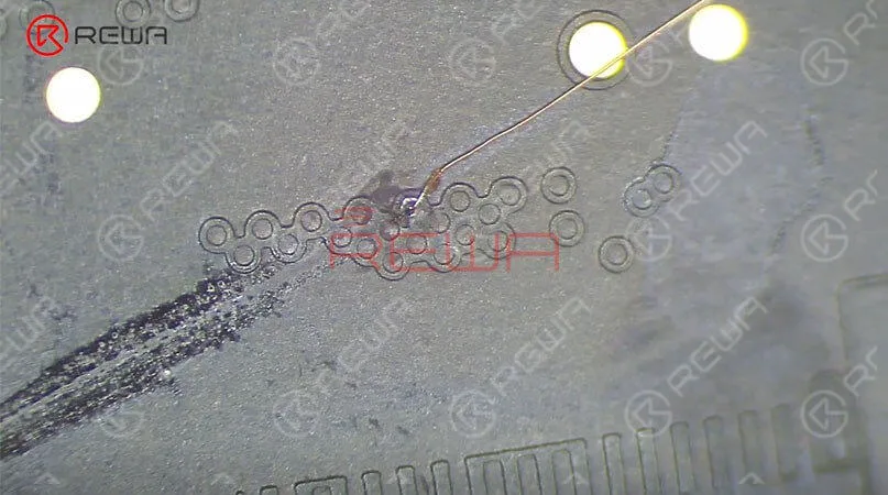
Then we need to locate WLAN_TO_PMU_HOST_WAKE. And the following step is to connect PP101_E-1 (the test point of the baseband wake signal) with PP7611_W-1 (the test point of the WiFi wake signal) by jumping a wire.
Before that, we need to scrape off the insulating coating on the two test points first, then apply some solder paste to the two bonding pads and heat with Soldering Iron at 365℃.
The next step is to tin the two bonding pads with solder paste and also to connect PP101_E-1 to PP7611_W-1 with 0.02mm Enameled Copper Wire.
Finally we need to coat the wire with the UV Curable Solder Mask.
Assemble the Phone and Test
Now we can assemble the phone and test. We got the motherboard installed and displayed assembly connected, then connected the battery.
Then pressed the power button to turn on the phone inserted the SIM card. After that, with the screen off, we tested again. And we found all going well.
PS: The repair case of this blog is applicable to the QCOM version, which might be a reference for the Intel version as a repair method.
iPhone gets stuck on the Apple logo, which usually means that there is a problem with the operating system or hardware of the phone.
Today, we will show you a rare case of iPhone X stuck on apple logo, and teach you how to diagnose and fix the problem step by step.
Cosmetic Inspection
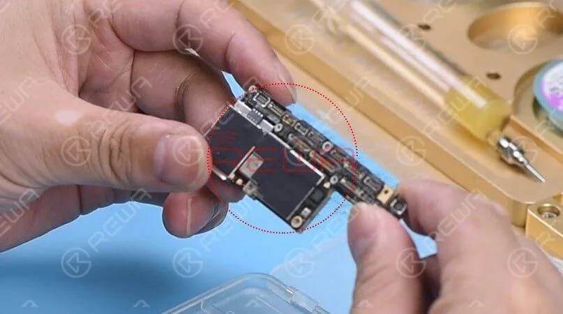
As we always do, we should run a cosmetic inspection of the motherboard first.
Check out the condition of the motherboard, whether it is deformed or water damaged.
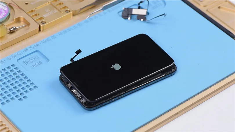
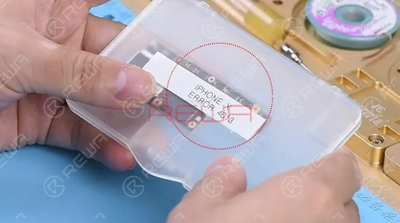
Then get the motherboard installed, the phone enters into recovery mode automatically.
Judging by this, the motherboard comes with restore failure. Therefore, the phone cannot enter into the system normally.
Diagnosis
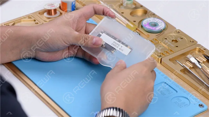
Let’s restore the phone with 3U Tools and check whether it comes with error 4013.
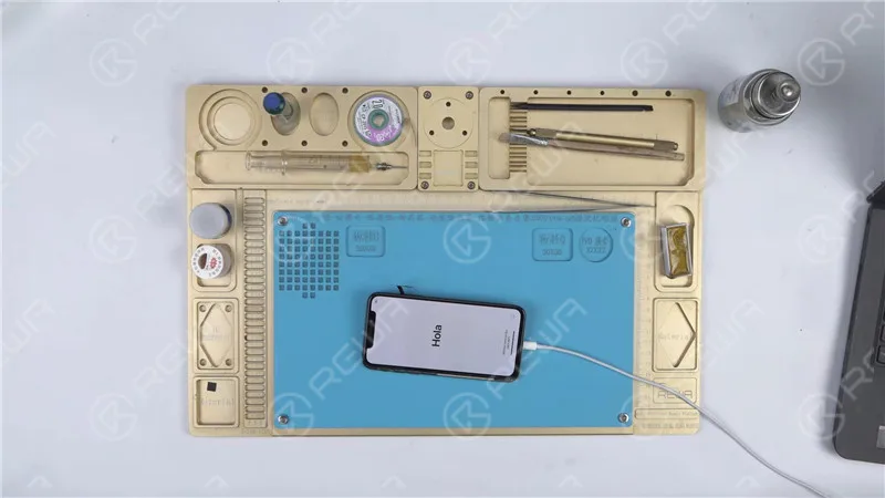
The phone can be normally activated after restore.
Next, check baseband info in the settings. If it shows normal, we can confirm now that the motherboard is normal. The fault is probably related to other parts.
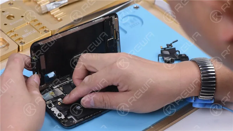
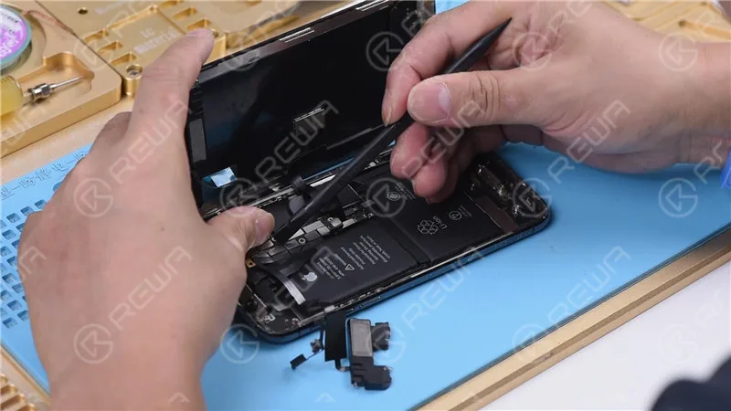
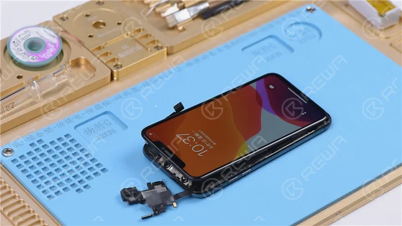
Get the earpiece speaker and sensor flex cable and front camera flex cable installed.
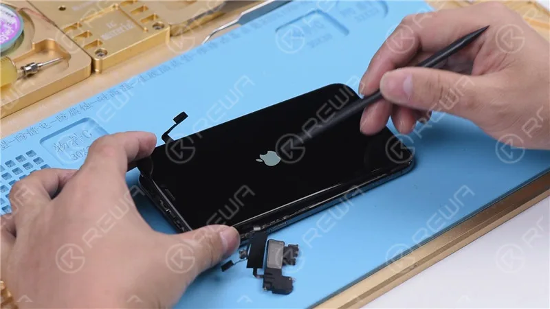
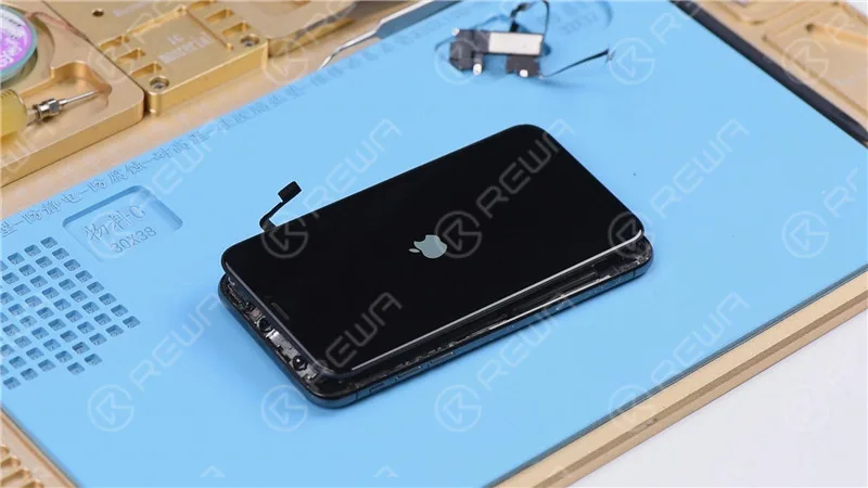
Turn on the phone, the phone is stuck on the Apple logo and keeps restarting.
Judging by this, the fault is related to the earpiece speaker and sensor flex cable or the front camera flex cable.
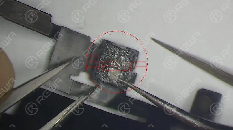
Check the earpiece speaker and sensor flex cable carefully, we find that the Flood illuminator module is moldy.
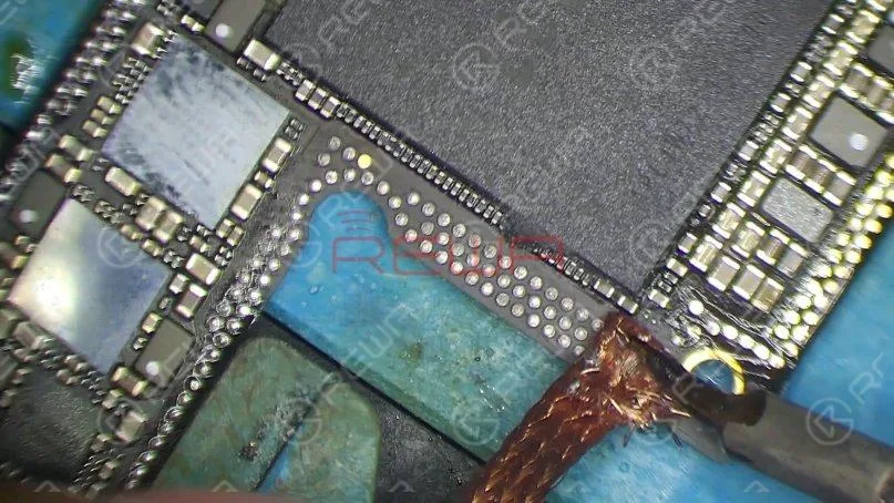
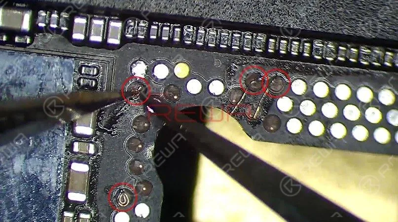
Remove the Flood illuminator module, we can see that its bonding pad is severely corroded.
That’s what’s causing the problem.
Maintenance
The next section will explain the detailed repair steps:
Apply some paste flux to the bonding pad.
Clean the bonding pad with Soldering Iron.
Apply solder paste to the severely corroded pad.
Clean with PCB Cleaner afterward.
Apply some paste flux to the bonding pad.
Get the Flood illuminator module in the right position.
Solder it with Hot Air Gun.
Test
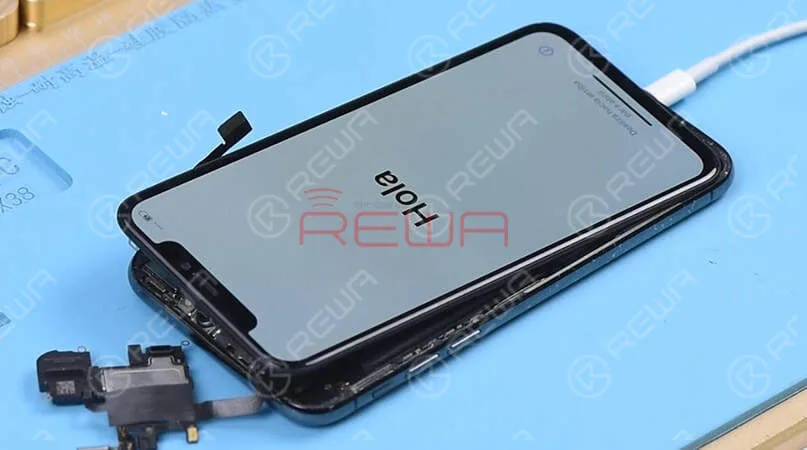
Get the earpiece speaker and sensor flex cable installed, then assemble the phone.
The phone turns on normally. Since the two flex cables were not connected during the previous restore, we need to restore again with the two connected.
Restore the phone with the help of 3U Tools.
Once completed, the phone enters the system normally, and Face ID works normally.
The repair process requires not only professional theoretical knowledge but also proficient handwork skills.
Start your learning journey with REWA ACADEMY now!
Attach a known good lower layer to the test fixture and then attach the upper layer.
Get the display assembly connected.
Running test, we can found that the phone turns on normally and the touch function is also normal.
Judging by this, the touch issue is caused by the lower layer.
Board Swap
Since the lower layer is badly deformed, we need to transplant baseband CPU, baseband EEPROM and the NFC chip on the original lower layer to a new lower layer.
For more details, please check out the video below:
After board swap, we should running test again by using Test Fixture.
Connect the battery connector with the DC Power Supply.
Then get the motherboard powered on with tweezers.
Here we can find IMEI serial number and modem firmware which indicates that the lower layer swap has been completed successfully.
Motherboard Recombination
Next thing we do is to solder the two layers together.
Here are the following steps:
Attach the new lower layer to the specialized reballing mold.
Cover the new lower layer with the matched reballing stencil.
Smear some low-temp Solder Paste on the stencil.
remove the reballing stencil carefully.
Continue to place the new lower layer onto the heating platform.
Waiting for the solder paste melting, solder balls start to shape up.
Waiting for the lower layer to cool for 10 minutes.
Apply BGA Paste Flux to the third space PCB, get the upper layer in position.
Heat for 1 minute on the heating platform at 160 degrees.
With the upper layer sinking and Paste Flux flowing, the two layers have been soldered together successfully.
Wait for the double-stacked motherboard to cool for 5 minutes.
True Tone Restoration
After we finish repairing the motherboard, it’s time to transplant parts.
REWA has years of experience on providing wholesale services upon an extensive range of electronic related products covering mobile phone spare parts and replacement battery.
We adhere to the principle of ” Quality Above All ” through the whole producing and testing processes. Here are some of our selected products:






 English
 Español
 Français
 Deutsch
 Italiano