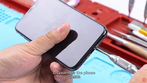
iPhone won’t turn on and the screen is black or frozen? After software issue being excluded, the problem may be caused by a faulty logic board. Since logic board of iPhone X is a single one that’s basically been folded over and soldered together, the unique design and structure have made any repairs to the logic board far more difficult than previous series. With our iPhone X won’t power on repair case today, the fault has been confirmed as inductor damage by voltage measurement. And we can fix the iPhone X won’t turn on issue by inductor replacing and board re-soldering. Let’s check out the video to see how to fix iPhone X black screen issue.
Tag: iphone x won’t turn on
-
iPhone X Won’t Turn On Repair – Thermal Imager Applied
Rosin and the freeze spray are the two commonly used and low-cost methods for faulty components locating when repairing logic boards. Still, you can use the Thermal Imager instead for more efficient repair work if the two methods become time-consuming. Check our video today and you will be surprised at how the Thermal Imager is used in iPhone X won’t turn on repair.
-
Troubleshooting iPhone X Won’t Turn On due to Large Boot Current
Today’s repair course focuses on troubleshooting an issue where the iPhone X does not turn on despite having a large boot current. To begin, conduct a thorough visual examination of the motherboard to ensure there are no signs of deformation or water damage.
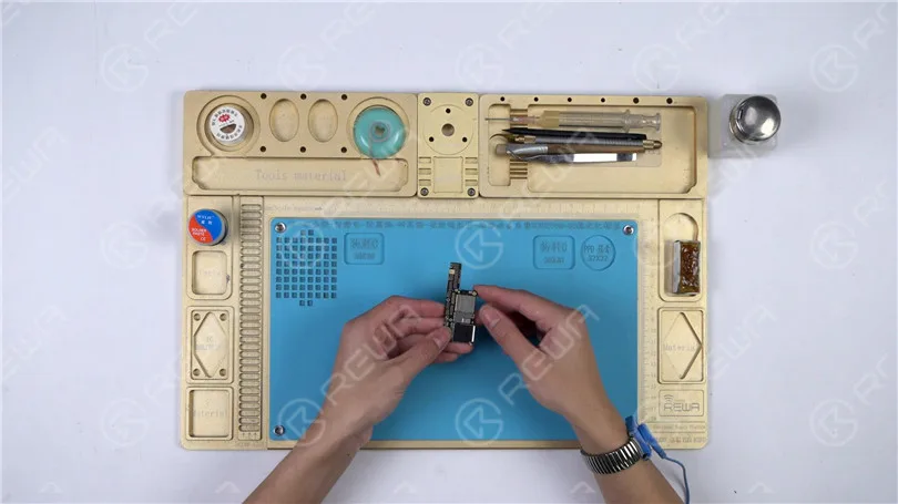
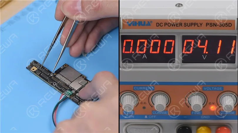
Connect the battery connector with the DC Power Supply. Get the motherboard booted up with tweezers. The boot current is larger than normal value. Judging by this, the three main power supply rails, PP_VDD_MAIN PP_BATT_VCC and PP_VDD_BOOST are in normal condition. The fault is probably related to the 17 power supply rails outputted from PMU.
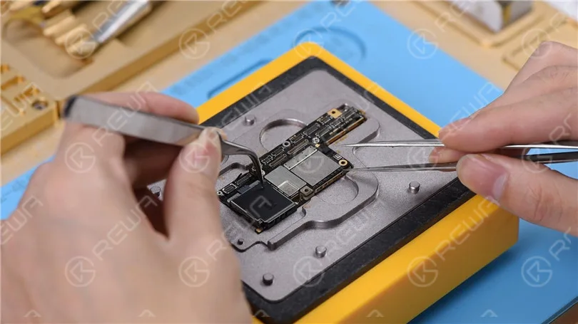
Now we need to separate the motherboard and confirm whether the fault is related to the upper layer or the lower layer. Place the motherboard on the specialized Heating Platform. Power on the heating platform and set the temperature at 160℃. With temperature of the platform reaching 160℃, try to push the upper layer with tweezers. With the upper layer being loose, pick up the upper layer with tweezers carefully. Tips: please be careful when separating the motherboard. With solder balls on the third space PCB remaining the same, we can skip the reballing process when soldering the two layers back together. Continue to take the lower layer off the platform.
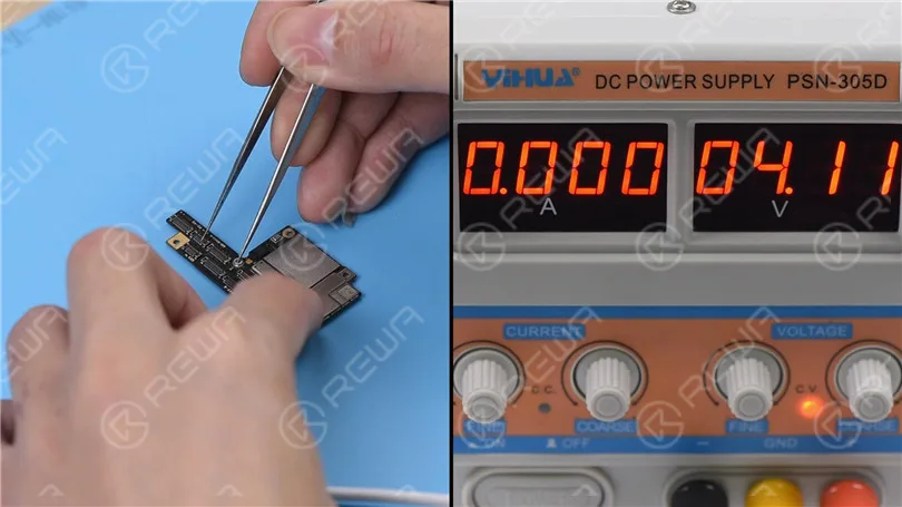
Now we can test the upper layer. Connect the battery connector on the upper layer with the DC Power Supply. Get the upper layer booted up with tweezers. The boot current is still larger than normal value. We can confirm now that the fault is related to the upper layer. Our next step is to check the 17 rails one by one.
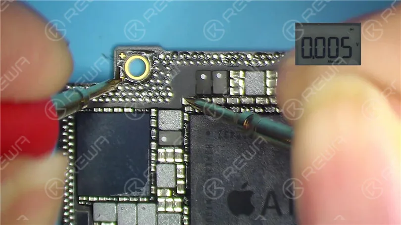
Let’s start with PP_CPU_PCORE. Locate C2701, one of the test points of PP_CPU_PCORE on the bitmap. Run diode mode measurement of a capacitor on C2701 relevant circuit. The measured value is normal. Continue measuring test points of the remaining 16 rails. Judging by the measured value, PP3V0_NAND has shorted. Since there are many components on PP3V0_NAND, we can locate the faulty component with rosin detecting.
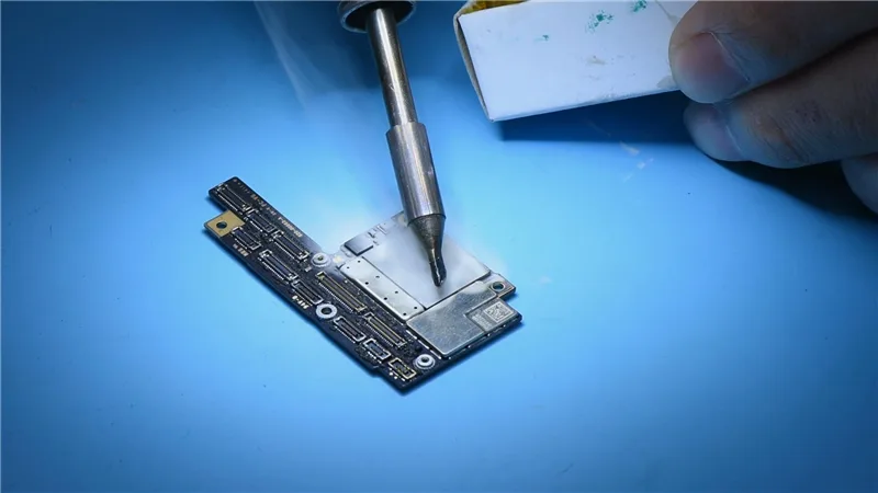
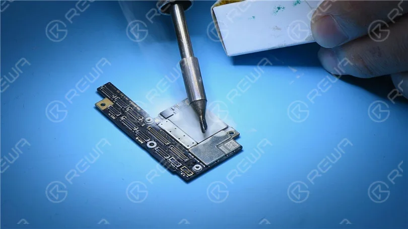
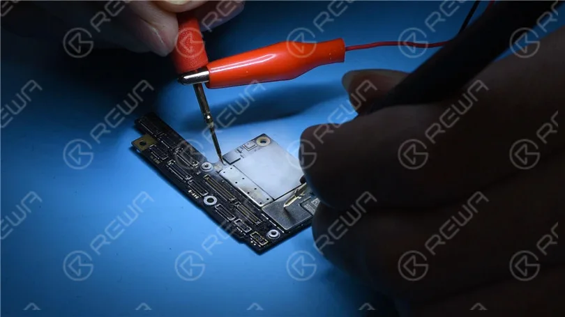
Dip some rosin with the Soldering Iron at 350℃. Then smoke rosin on components on PP3V0_NAND. Set the output voltage of the DC Power Supply at 3V and get the black probe grounded. Meanwhile, get the red probe touched with a capacitor on PP3V0_NAND. Please be noted that the red probe shouldn’t stay too long on the capacitor. We can see that rosin on C2649 melts immediately. Judging by this, C2649 has been damaged. Let’s try to detach C2649 from the board.
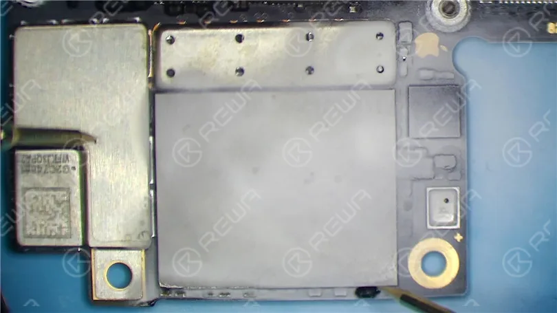
Attach the upper layer to the PCB Holder. Remove black adhesive around C2649 with QUICK Vertical Wind Hot Air Gun at 260℃, air flow 2. Then detach C2649 from the board. Again, get the red probe grounded. Touch the two pins of C2649 with the black probe. The measured value is normal.
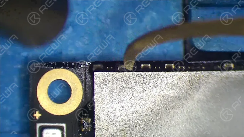
We can confirm now that the shorted condition is caused by damage of C2649. Still, we need to test the upper layer. Remove the upper layer and clean with PCB Cleaner. Connect the battery connector on the upper layer with the DC Power Supply. Get the upper layer booted up with tweezers. The boot current is normal this time. Please be noted that due to differences in board versions and systems, the boot current of some upper layers might be 50mA, which is normal.
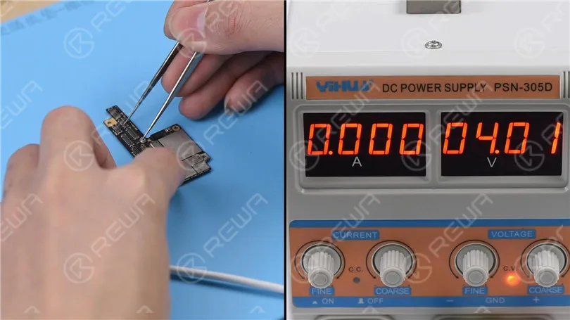
Next thing we need to do is to solder the two layers together. Before soldering, we need to remove heat insulation adhesive on the lower layer. Then clean with PCB Cleaner. Continue to place the lower layer onto the heating platform. Power on the heating platform. With temperature of the platform reaching 60℃, apply some Paste Flux to the third space PCB.
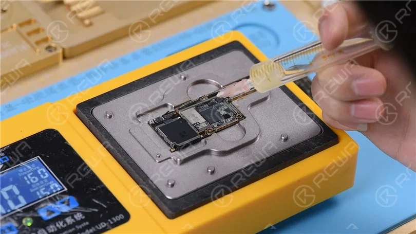
Then get the upper layer in position. With temperature of the platform reaching 150℃, push the upper layer with tweezers slightly. If the upper layer returns to the previous position automatically, then the soldering process is completed.
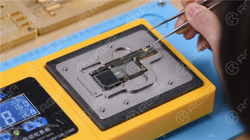
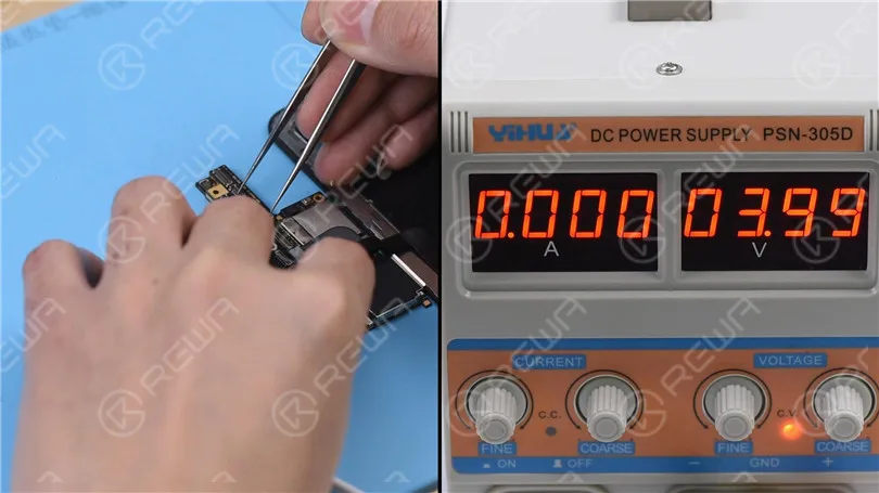
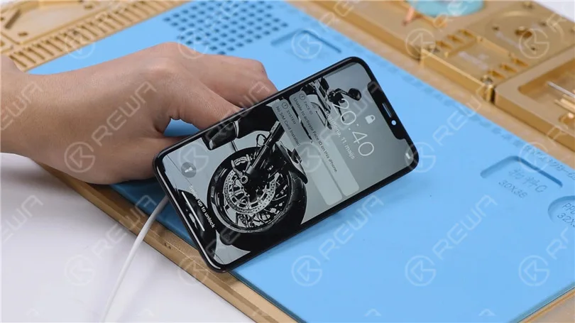
Power off the heating platform. Take the motherboard off the platform. Wait for the motherboard to cool for 2 minutes. Get the display assembly installed. Connect the battery connector with the DC Power Supply. Get the motherboard booted up with tweezers. The boot current is normal. The phone comes with normal display. And can get access to the system. Fault cleared.
If you want to learn more iPhone repair knowledge, please visit REWA Academy.
-
How To Fix iPhone X Won’t Turn On By Board Swap | iPhone Repair Tips
This is a real-life repair case from REWA chip-level motherboard repair service. The iPhone X motherboard was severely damaged with a hole in the upper layer during the reassembling process, resulted in an iPhone X won’t turn on issue. Follow our guidance in the video today and learn how to diagnose and troubleshoot the double-stacked motherboard step by step.
-
iPhone X Won’t Turn On Quick Fix – Thermal Imager Applied
Rosin and the freeze spray are the two commonly used and low-cost methods for faulty components locating when repairing logic boards. Still, you can use the Thermal Imager instead for more efficient repair work if the two methods become time-consuming. Check our iPhone X quick fix repair guide today and you will be surprised at how the Thermal Imager is used in iPhone X won’t turn on repair.
Problem
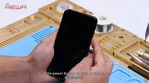
Hold the power button to turn on the phone. The phone won’t turn on. Take apart the phone and disconnect the battery. Remove the screen and take out the motherboard.
Diagnosis
Let’s check the boot current first.Connect the battery connector with the Power Supplier and press power button on the Power Supplier. The system will then detect power button press. We can see that the current reading on the ammeter is larger than normal value.
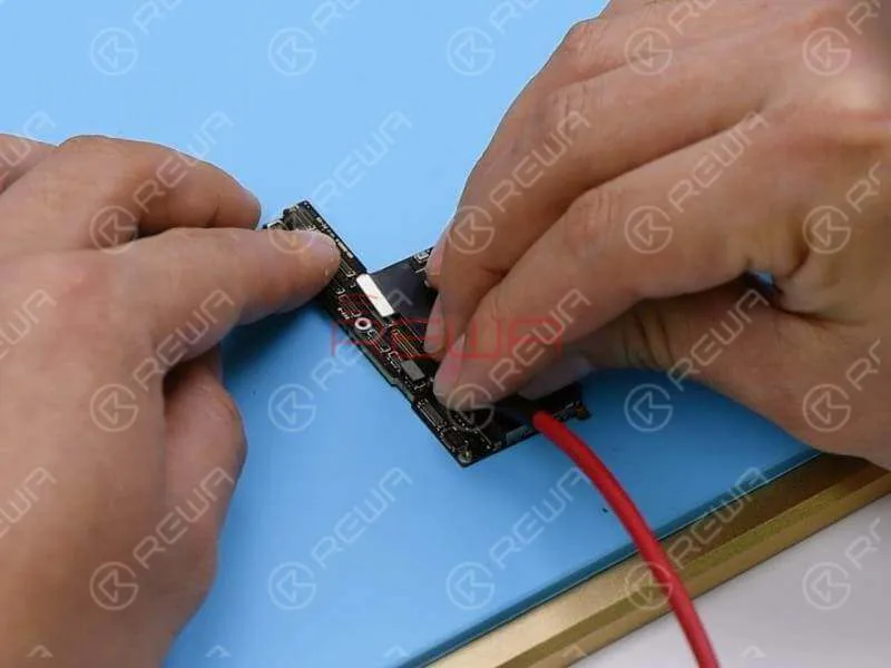
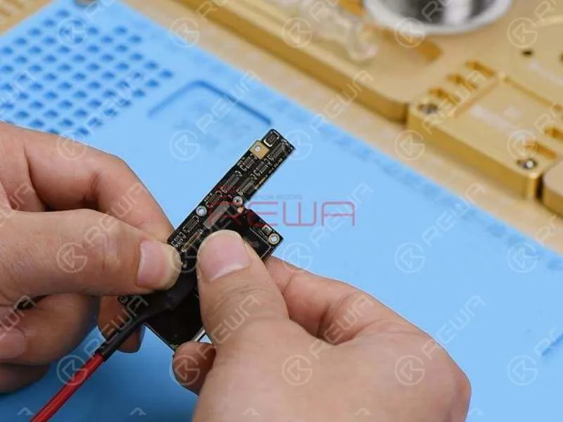
Touch the motherboard with one hand. The NAND flash chip and the area surrounding it are hot. Which indicates that rails on the area might have shorted. Since there are so many components on the hot area, we can locate the faulty component with the help of the Thermal Imager.
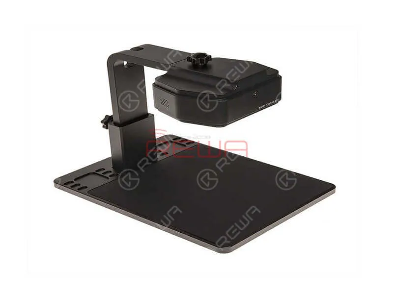
Thermal Imager
Features
This infrared thermal imager can detect the running temperature of motherboard chips, resistors and capacitors with the help of its built-in PC intelligent analysis software and intelligent algorithm.
This infrared thermal imager can help locate the current leakage/short-circuit position quickly.
It can greatly improve the efficiency and accuracy of your daily repair work with advanced technology.
Features a lifting bracket with removable design, the thermal imager is easy to assemble and carry.
You can also replace the visible lens of the thermal imager with electron-microscope lens and make it act as an electronic microscope.
The bracket can be adjusted by the knot to reach the best observation distance.
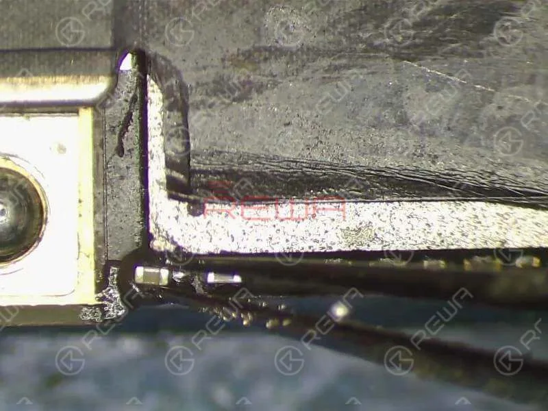
Put the motherboard under the Thermal Imager. Get the motherboard powered on. We can see clearly that C2647 is extremely hot. Judging by this, C2647 is probably damaged.
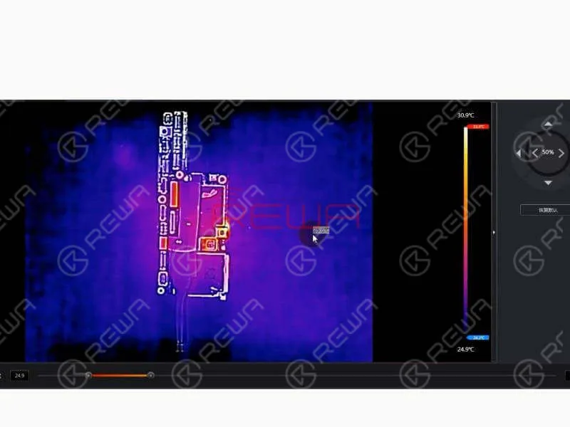
Let’s remove C2647 and run diode mode measurement of its bonding pad. The measured value is normal. We can confirm now that C2647 is damaged.
Troubleshooting
Let’s replace with a new capacitor and see how it works. Clean the bonding pad and apply some Paste Flux to the bonding pad. Then solder a new capacitor onto the board.
Reassemble And Test
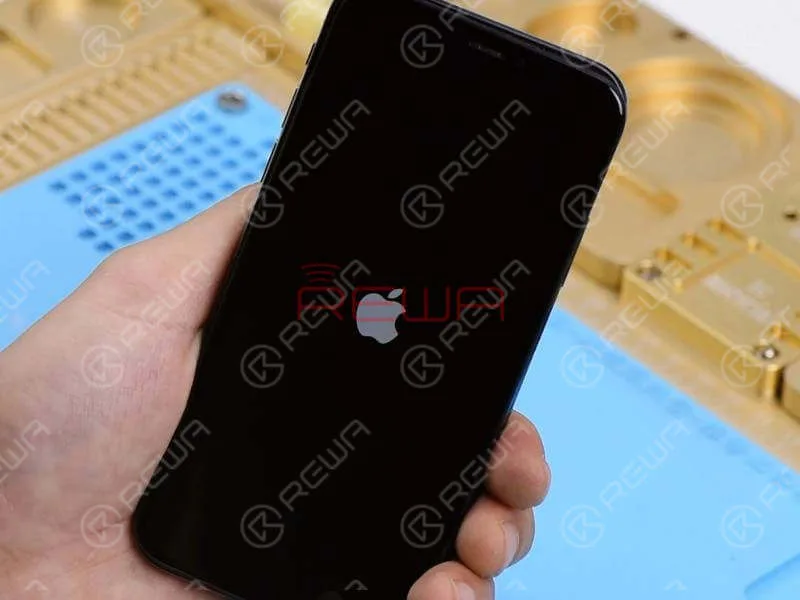
Assemble the phone and test. The phone turns on normally.
Tools Used:
- Multifunctional PCB Holder for iPhone X
- Hot Air Gun Rework Station
- Integrated Mobile Phone Repair Platform
- Electron Microscope
- Thermal Imager
- iPhone Disassembling Tool Kits
You can also visit REWA YouTube Channel to check our video and learn how to fix iPhone X won’t turn on quickly and efficiently.
-
iPhone X Won’t Turn On? Fix it with Board Swap – Repair Case Study
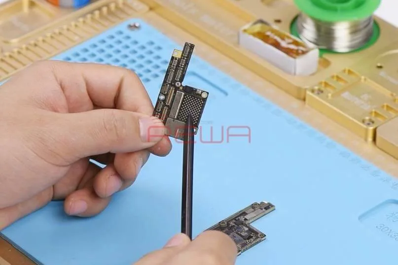
This case involves an actual repair scenario handled by REWA’s chip-level motherboard repair service. During the reassembly process, the iPhone X motherboard suffered significant damage, including a hole in the upper layer. As a result, the iPhone X experienced a failure to turn on. In today’s blog post, we provide detailed instructions on how to diagnose and troubleshoot the double-stacked motherboard, offering a step-by-step guide.
Diagnosing
Run cosmetic inspection of the motherboard. The motherboard is not water damaged or deformed.
Connect the battery connector with the DC Power Supply and get the motherboard powered on with tweezers. The boot current reading is larger than normal value.
Judging by this, circuits on the motherboard might have shorted.
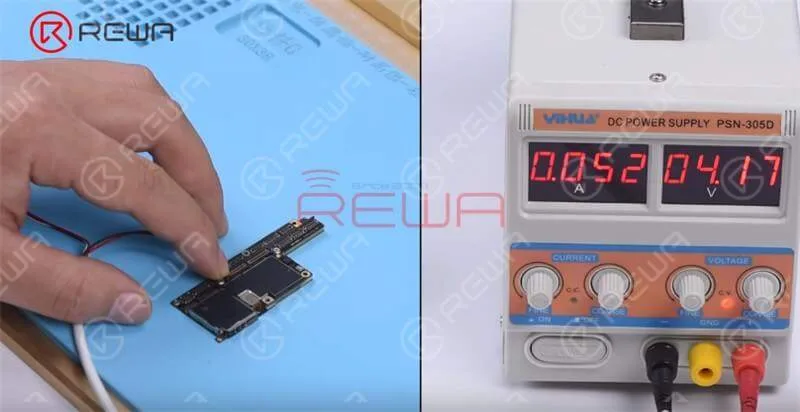
Disconnect the power supply. First, we need to remove the dustproof sponge on the motherboard. Then run diode mode measurement of the battery connector. The measured value of Pin 1 of the battery connector is 11, which is abnormal. Normal value should be 350 or so.
Continue measuring Pin 35 of the display connector J5700. The measured value is 12, which is also abnormal. Normal value should be 350 or so.
We can confirm now that the main power supply circuits of the motherboard have shorted or the motherboard is leaking electricity.
Troubleshooting
Next, we need to separate the motherboard to confirm whether the fault is related to the upper layer or the lower layer.
Put the motherboard on the Heating platform and set the temperature to a range from 150℃ to 160℃. With temperature of the platform reaching 137℃ and solder balls on the third space PCB starting to melt, try to pick up the upper layer with tweezers. Then pick up the lower layer.
Check the upper layer under the microscope. We can see clearly that the charging IC U3300 is damaged.
Apply some paste flux to the charging IC. Heat with the QUICK 861D Helical Wind Hot Air Gun at 380℃, airflow 45 to remove the charging IC. Clean the bonding pad afterwards.
We can see that the PCB has also been severely damaged. There is a large hole in the upper layer.
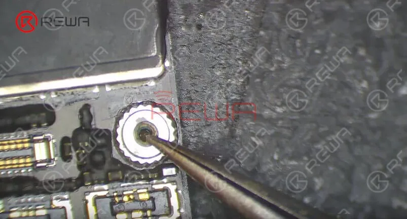
These evidences lead to the conclusion that a long screw was used by the last repair technician when reassembling the phone. What’s more, he applied too much force when fitting the screw into the screw hole and punched a hole in the upper layer.
The upper layer has been badly damaged and cannot be repaired anymore. We need to transplant CPU, EEPROM, and NAND on the upper layer onto a new upper layer.
Here we recommend using a specialized upper layer with CPU, EEPROM, and NAND previously removed.
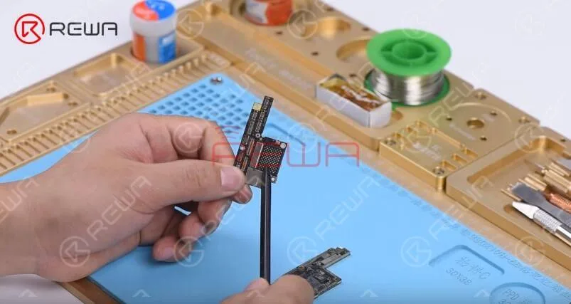
iPhone X Board Swap
Remove NAND+CPU+EEPROM
Attach the damaged upper layer to the PCB Holder. Heat with the QUICK 861D Helical Wind Hot Air Gun at 280℃, air flow 45.
Remove black adhesive around the NAND.
Continue to heat the NAND with the hot air gun at 400℃, air flow 45 for about 30 seconds. Then pry up the NAND carefully.
Continue to detach CPU and EEPROM from the board.
iPhone X Board Swap
Clean CPU+NAND+EEPROM
Now we need to clean the three chips one by one.
Apply some medium-temp solder paste to the bonding pad of CPU. Clean the bonding pad with Soldering Iron at 365℃. Then heat with the QUICK 861D Helical Wind Hot Air Gun at 300℃, air flow 30 and remove black adhesive on the bonding pad with a specialized blade. And then clean the bonding pad with Solder Wick.
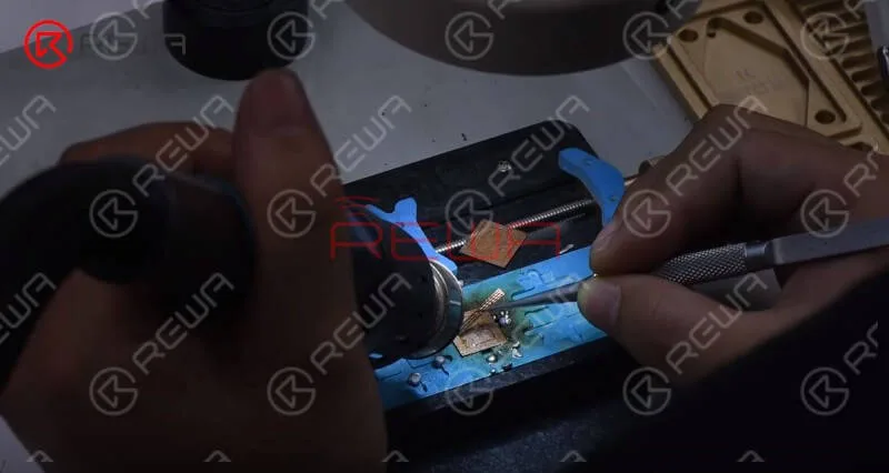
Once done, clean with the PCB Cleaner. Continue to clean NAND and EEPROM with the same steps.
iPhone X Board SwapReball CPU+NAND+EEPROM
Now we need to reball CPU, NAND, and EEPROM one by one.
Let’s start with CPU. Get the BGA Reballing Stencil in position. Smear medium-temp solder paste evenly on the stencil with BGA Scraper and heat evenly with the QUICK 861D Helical Wind Hot Air Gun at 330℃ so that solder balls can shape successfully. Once completed, wait for 1 minute. Then separate CPU from the stencil.
Continue to reball NAND and EEPROM with the same steps.
iPhone X Board SwapSolder CPU+EEPROM+NAND
Now we need to solder the reballing finished CPU, EEPROM and NAND to the new upper layer one by one. Before soldering, we need to clean corresponding bonding pads on the new upper layer.
Apply some medium-temp solder paste to the bonding pad of CPU. Clean the bonding pad with Soldering Iron at 365℃.
Tips: be careful not to cause bridging of components around when cleaning the pad. We can also apply some paste flux during the cleaning for smooth operation.
Then clean the bonding pad thoroughly with Solder Wick. Once done, clean with PCB Cleaner. Continue to clean the bonding pad of NAND and the bonding pad of EEPROM with the same steps. Once done, we can move on to the soldering process.
Apply some paste flux to the bonding pad of NAND. Get NAND in the right position. Solder with the QUICK 861D Helical Wind Hot Air Gun at 365℃, air flow 45. Once done, continue to get CPU and EEPROM soldered onto their bonding pads.
Motherboard Test
Now we need to test the motherboard.
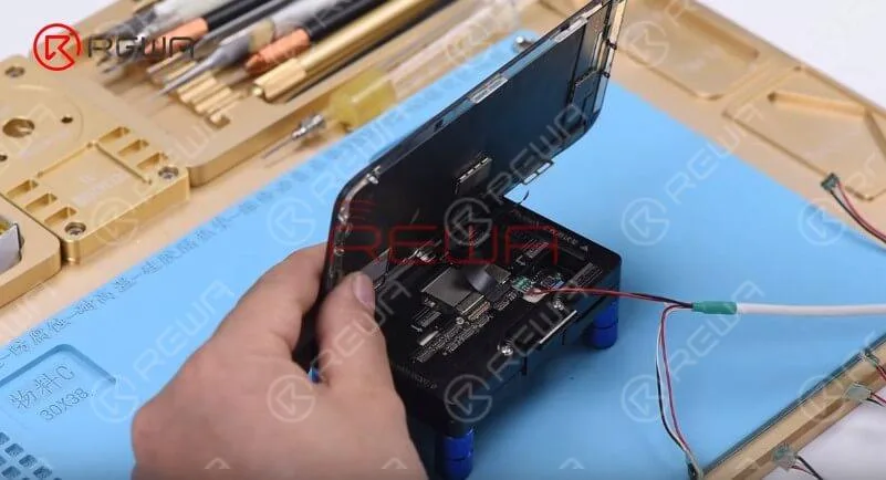
Attach the upper layer and the lower layer to the Test Fixture. Connect the upper layer and the lower layer with the display assembly. Connect the battery connector with the DC Power Supply. Get the motherboard powered on with tweezers. The phone turns on normally and can get access to the home screen.
Motherboard Recombining
Next thing we do is to solder the two layers together.
First, we need to reball the lower layer. Put the lower layer on the heating platform. Get the BGA Reballing Stencil in position and smear some low-temp solder paste on the stencil. Then remove the stencil carefully. Turn on the power switch of the heating platform. With solder balls shaping successfully, turn off the power switch and wait for 1 minute.
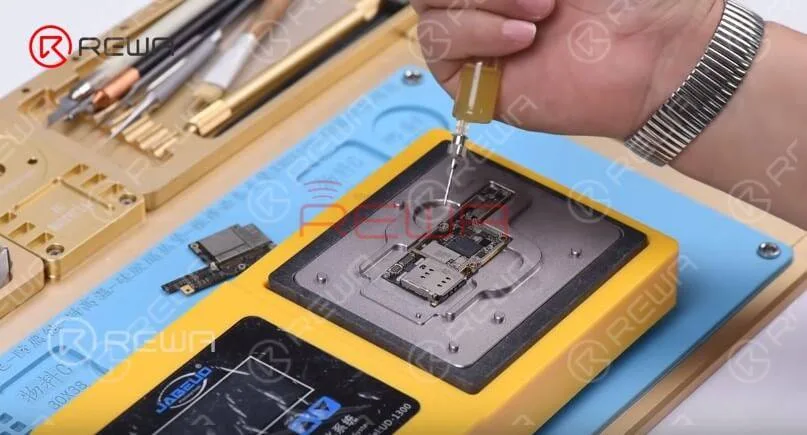
Continue to apply some BGA paste flux to the third space PCB. Get the upper layer in position. Turn on the power switch of the heating platform. With the upper layer sinking and paste flux flowing, continue heating for 1 minute.
Wait for the motherboard to cool down and then detach it from the platform.
Reassemble And Test
Now we can assemble the phone and test.
Get the motherboard and display assembly installed. Connect the battery and press power button. The phone turns on normally. Fault cleared.
Warm tips: get the phone full assembled after confirmation of fault clearance.
REWA LAB suggests that repair technicians keep a well-organized workspace and develop a good habit in their daily repair work. Follow operating procedures strictly and avoid unnecessary problems caused by carelessness.
Tools & Parts Used
You can also visit REWA Youtube Channel to check our video of iPhone X Won’t Turn On By Board Swap.
 English
 Español
 Français
 Deutsch
 Italiano