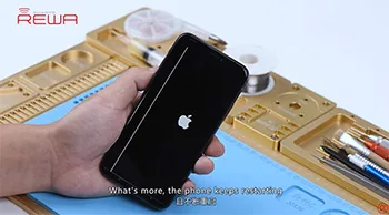
iPhone X features vertical lines on the screen and keeps restarting? How to narrow down the fault possibilities by ruling out one by one? How to confirm the fault and fix the problem? Let’s see how REWA engineer deals with it.
Tag: iphone x repair
-

iPhone X Incoming Calls Not Showing – Fixed By Jumping Wires
Right now, there are few solutions to fix iPhone not responding in sleep mode when getting incoming calls. The general repair process of a repair technician is to take out the motherboard, check PMU and baseband CPU, and then replace or re-solder the faulty component. The whole repair process is complicated and difficult. Check out our video today and REWA LAB will show you a brand new ‘signal borrowing’ solution to fix the problem quickly and efficiently.
- 00:00 Intro
- 00:26 Tools & Materials
- 00:56 Diagnosis
- 02:37 Confirm the Signal Location
- 03:27 Borrow Signal by Jumping a wire
- 05:50 Assemble the Phone and Test
-
iPhone X-12 Double-stacked Board Separation & Recombination | REWA Academy Tips
To separate and recombine the double-stacked motherboard is a very important step for motherboard repair of iPhone X and models above. Slight errors may result in pseudo soldering or other problems. REWA Academy students recently gave feedback that the two layers often fail to fit closely in double-stacked motherboard repair. There are even large gaps, causing pseudo soldering. In response, we will share tips and notes when separating and recombining double-stacked motherboard. The tips in this article apply to iPhone X and models above.
Separation
Peel off foam on the motherboard before heating. Please be noted that we do not recommend beginners to heat the motherboard with a hot air gun. Because the motherboard may receive heat unevenly and deform. A professional motherboard heating platform is what we suggest.
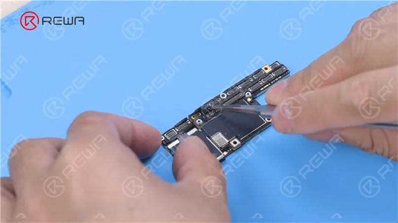
Heat the Motherboard
To facilitate later removal of the logic board, drive a screw on the logic board. Cut through the tape with a Sculpture Knife.
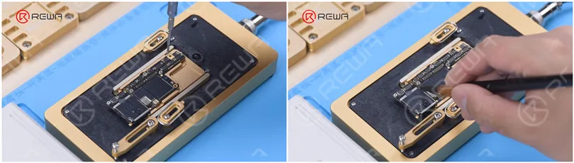
The logic board and middle layer are soldered with low-temperature solder paste. So the best temperature for the heating platform will be 155 °C-165 °C. Push the logic board gently with tweezers when the temperature reaches 165 °C. If the logic board is loose, the tin has melted.
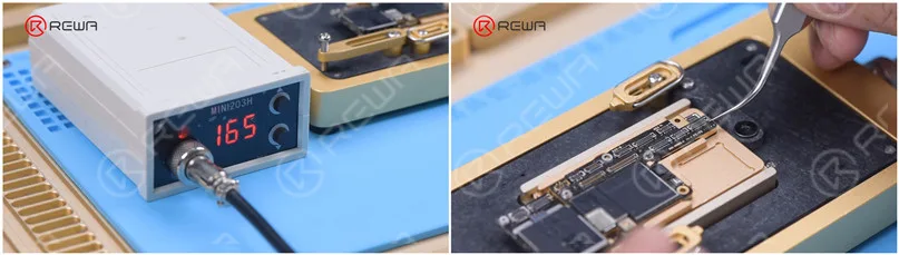
Clamp the screw to remove the logic board and then remove the signal board.
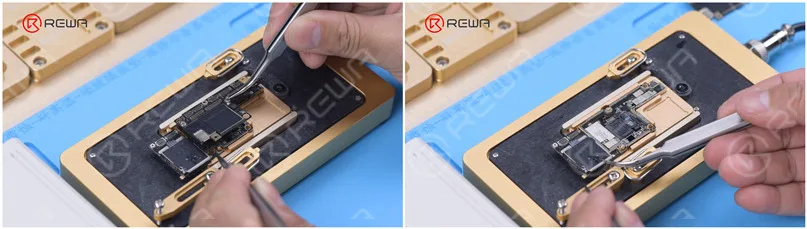
Motherboard Cleaning
Remove thermal grease with a Sculpture Knife. Thermal grease must be removed completely. Otherwise, the thermal grease will touch the logic board to give rise to pseudo soldering in recombination. Attach the signal board to the holder and apply a round of Paste Flux.
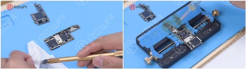
Remove tin on the bonding pad with micro soldering tools soldering Iron at 365 °C and Solder Wick. Tin on the bonding pad must be completely removed. The residual tin will affect the subsequent soldering. Clean the bonding pad with PCB Cleaner.
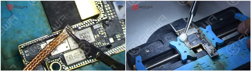
Clean the logic board with the same method. Please do not damage components around the bonding pad of the logic board while cleaning. It is necessary to check if the bonding pad is neat after cleaning.
Reballing
Attach the signal board to the Reballing Platform. Put the reballing stencil in position to make sure that it is pressing against the signal board. To prevent the solder paste from flowing into the motherboard gap, insert a metal plate.
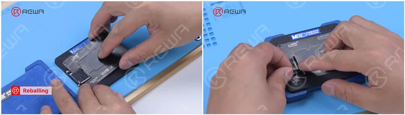
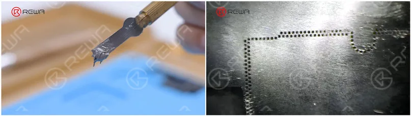
Apply a layer of low-temperature Solder Paste and wipe off excess solder paste with a Lint-free Wipe. Remove the reballing stencil. Check if solder paste on the signal board is full.
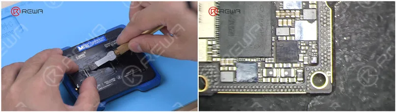
While applying solder paste, please make sure that solder paste must have a certain humidity. If the solder paste is too dry, it will adhere to the reballing stencil when the stencil is removed. As a result, the solder paste on the signal board will not be uniform, which can easily lead to poor soldering.
Recombination
Put the signal board on the 165 °C Heating Platform to heat. Stop heating after the solder balls are formed. Apply a small amount of Paste Flux after the signal board has cooled.
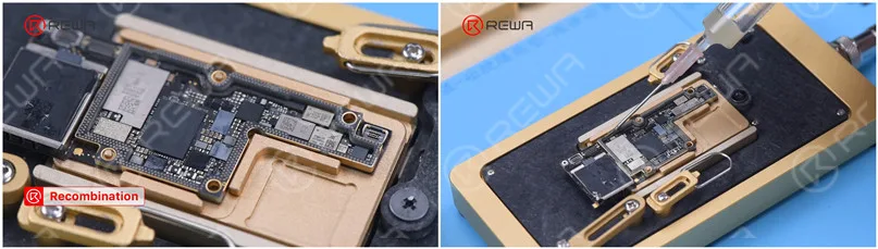
Align the logic board with the signal board. Keep heating on the 165 °C Heating Platform. When the solder flux spills and logic board sinks, nudge the logic board gently with tweezers to ensure the two layers fit closely. The nudge must be gentle and small.
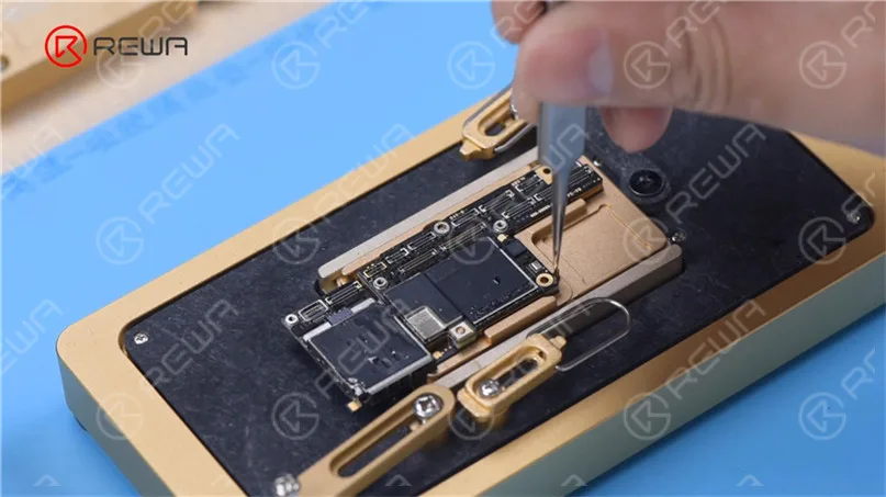
Clean the motherboard with PCB Cleaner after the motherboard has cooled.
If you find the motherboard deformed while recombining, you can put the motherboard on a flat board and fasten it with a rubber band. Press two sides of the motherboard gently. To avoid crushing components, please put a soft paper under the motherboard.
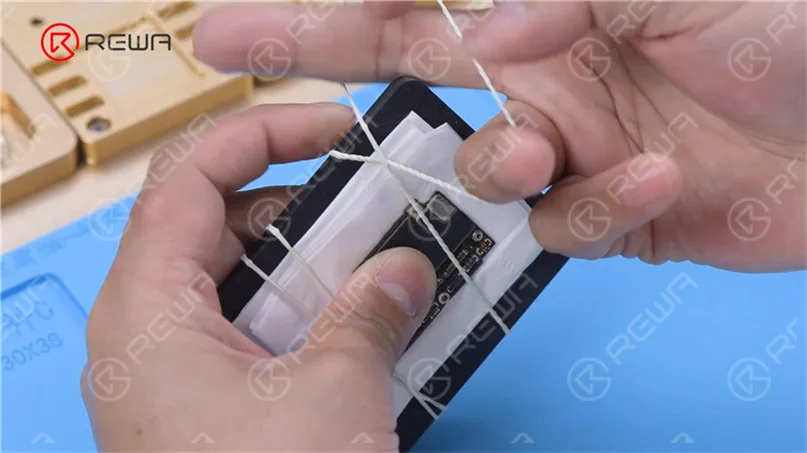
Next, we will share another recombination method. The method can be taken if the middle bonding pad is not damaged.
When the tin melts, remove the logic board in a vertical manner with tweezers. It can be seen that there is a metal pad of 0.05 mm thickness around the signal board at a certain distance. This metal pad is designed to keep a 0.05 mm gap between the logic board and the middle layer, preventing the solder balls from bridging while soldering.
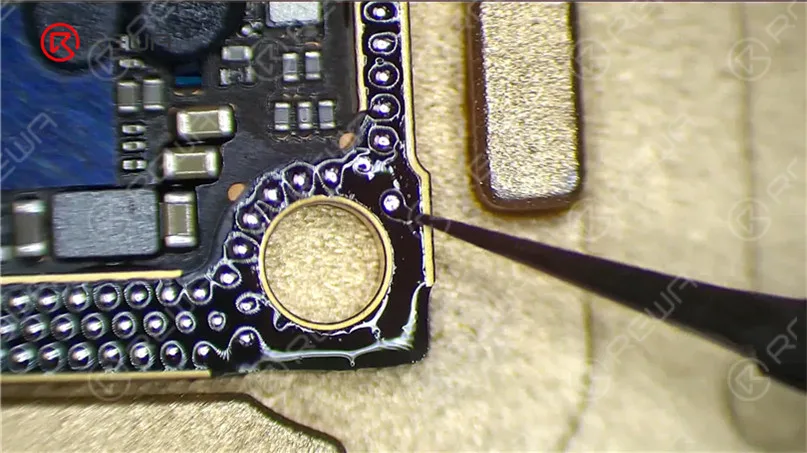
You only need to remove thermal grease on the motherboard when the repair is done. Keep original tin on the bonding pad and apply a small amount of Paste Flux.
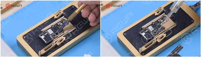
Lastly, align the logic board with the signal board. When the temperature reaches 165 °C and the tin melts, turn the power off. Press two ends of the logic board with tweezers until the motherboard has cooled. The logic board and the signal board fit closely in this way. There will be no bridging and solder balls spillover.
Visit REWA Academy if you want to learn more repair skills. We have complete course packages for motherboard diagnosis and repair ability improvement. Feel free to leave a comment of your thought on double-stacked motherboard separation and recombination.
Watch the full video below to see how we separate and recombine a double-stacked motherboard.
-
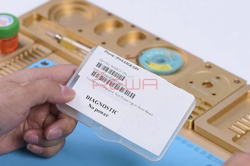
iPhone X Won’t Turn On? Fix It with Large Boot Current
Discovering that your smartphone refuses to power on is the ultimate fear of any device owner. It’s a dreadful experience to encounter a blank screen devoid of any signs of life. In this instance, REWA LAB has a repair case to offer, focusing on resolving the issue of an unresponsive iPhone X.
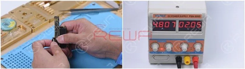
Step 1: Power up the motherboard for testing
To start, establish the connection between the motherboard and the power supply. If the DC POWER SUPPLY exhibits a higher current reading than usual without initiating the boot-up process, it indicates a short circuit in the motherboard’s main power supply line.
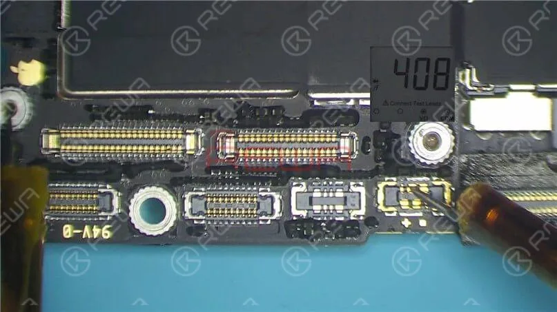
Step 2: Run diode mode measurement
Run diode mode measurement of the J3200 pin 1. The diode value is 408, which means the main power supply line PP_BATT_VCC is normal.
Then measure the J5700 pin 35. The diode value is 0, which means the main power supply line PP_VDD_MAIN is short-circuited.
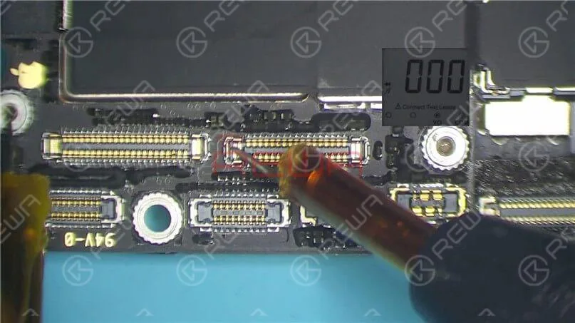
Since the PP_VDD_MAIN line simultaneously supplies power for the logic board and signal board, we need to separate the motherboard to identify the fault location.
Step 3: Motherboard separation
Cut through the shielding paper with a sculpture knife and put the motherboard on the Heating Platform.
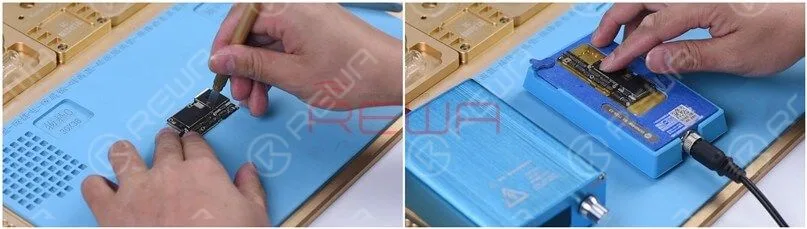
To make it easier to remove the logic board after separation, drive a screw on the logic board.
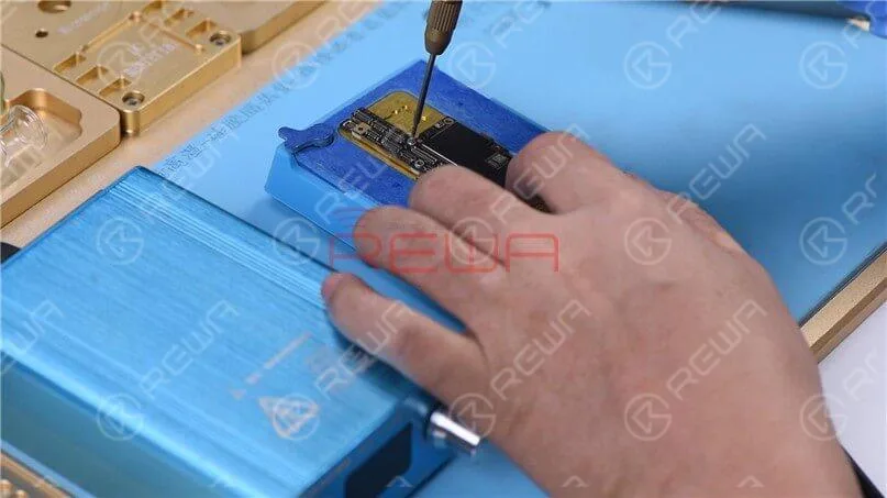
Set the temperature to 170℃. When the temperature reaches 170℃, use tweezers to remove the logic and signal board.
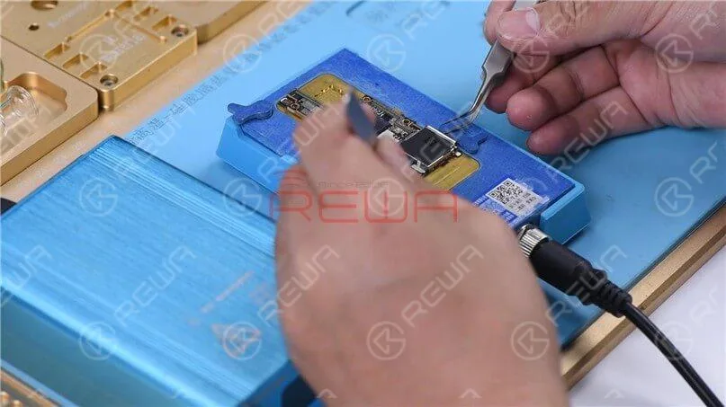
Step 4: Run diode mode measurement again
Run diode mode measurement of the J5700 pin 35 on the logic board. The diode value is 0. It indicates that the main power supply line PP_VDD_MAIN of the logic board is short-circuited.
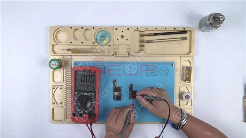
Measure the S73 pin of the signal board. The diode value is 306, which means the signal board is normal.
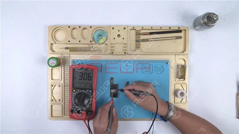
Through the diode mode measurement, it can be confirmed that the fault is on the logic board.
Step 5: Locate and clear the fault
Remove the thermal grease on the logic board.
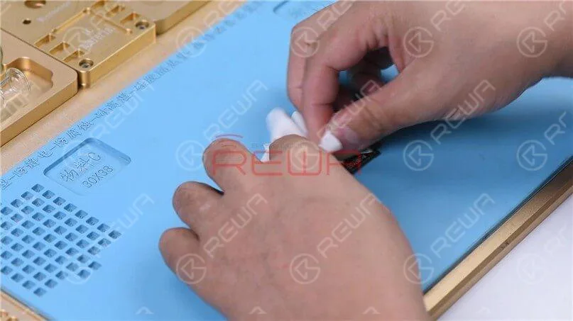
Then we can locate the faulty component with rosin detecting. Smoke some rosin with the Soldering Iron at 365℃.
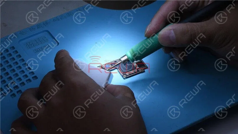
Apply a 3V0 voltage to the S74 pin of the logic board. We can see that the rosin on C2990 has melted. It can be confirmed that C2990 has been damaged and needs to be removed.
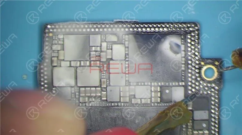
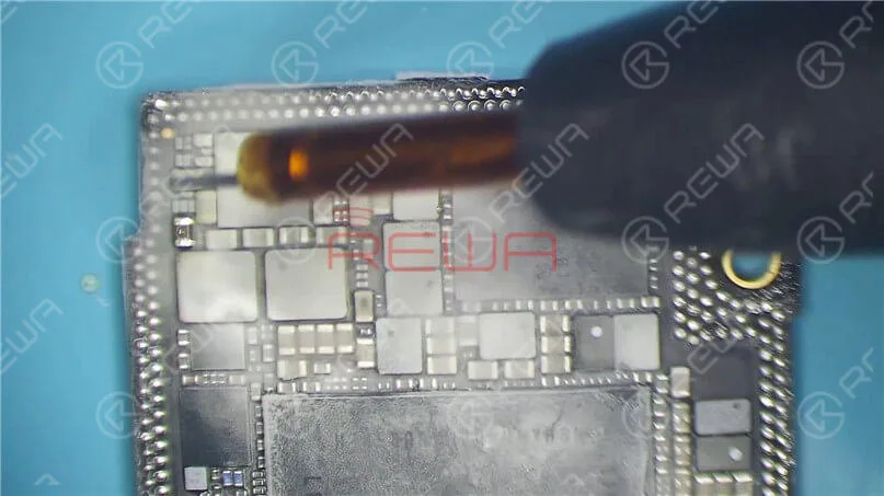
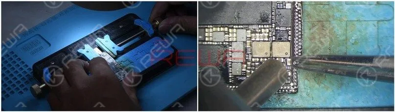
Attach the logic board to the PCB Holder. Then remove C2990 with QUICK 990 AD Hot Air Gun at 360℃ and airflow 3.
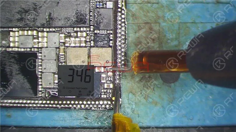
Measure the logic board again after it has cooled. The diode value returns to a normal value of 346. The fault is cleared.
Step 6: Motherboard restoration
Smear rosin with Soldering Iron and solder-wick. Remove the tin on the bonding pad of the logic board and signal board separately.
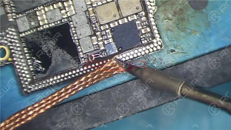
Clean the motherboard with PCB Cleaner. Remove excess thermal grease on the signal board with a sculpture knife.
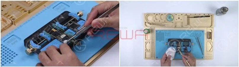
Attach the signal board to the Reballing Platform and place the Reballing Stencil in position. Apply a layer of low-temperature Solder Paste evenly.
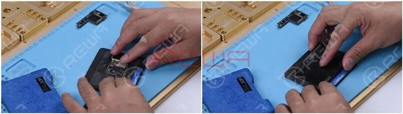
After reballing, put the signal board on the Heating Platform at 170℃. When the solder ball is formed, turn off the power and cool the signal board.
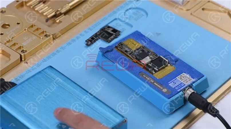
Apply a small amount of Paste Flux. Align the logic board with the signal board and put it on the Heating Platform at 170 ℃.
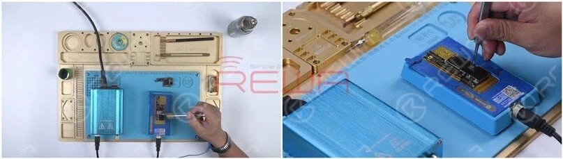
When the temperature has risen to 170℃, continue heating for another minute. Install the motherboard on the phone after cooling it for 5 minutes.
Step 7: Boot up and test
Boot up and test. The phone turns on normally and the fault is eliminated.
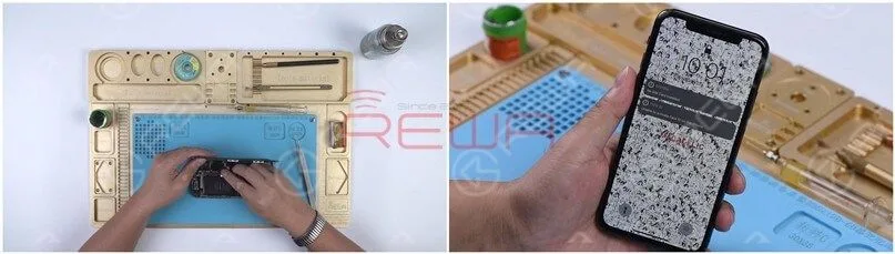
Conclusion
The iPhone X fails to power on and the motherboard experiences excessive current flow without initiating boot-up. By utilizing a multimeter to assess the primary power supply line on the motherboard, it was determined that the PP_VDD_MAIN line has a short circuit. After isolating the motherboard and conducting a subsequent measurement, we confirmed that the issue resides within the logic board. Through the use of rosin detection, we identified that C2990 had sustained damage. Removing C2990 resolved the problem.
For further repair content, please visit REWA academy website or explore our online shop for repair tools and parts. Also, subscribe to our YouTube channel to access additional phone repair information and techniques.
-
iPhone X Won’t Turn On Quick Fix – Thermal Imager Applied
Rosin and the freeze spray are the two commonly used and low-cost methods for faulty components locating when repairing logic boards. Still, you can use the Thermal Imager instead for more efficient repair work if the two methods become time-consuming. Check our iPhone X quick fix repair guide today and you will be surprised at how the Thermal Imager is used in iPhone X won’t turn on repair.
Problem
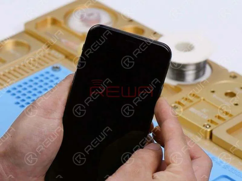
Hold the power button to turn on the phone. The phone won’t turn on. Take apart the phone and disconnect the battery. Remove the screen and take out the motherboard.
Diagnosis
Let’s check the boot current first.Connect the battery connector with the Power Supplier and press power button on the Power Supplier. The system will then detect power button press. We can see that the current reading on the ammeter is larger than normal value.
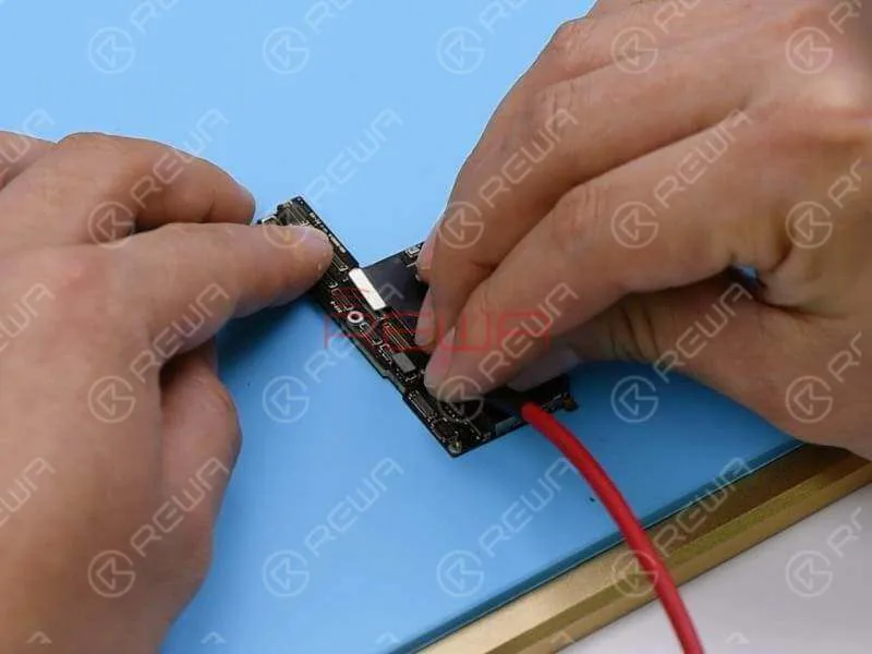
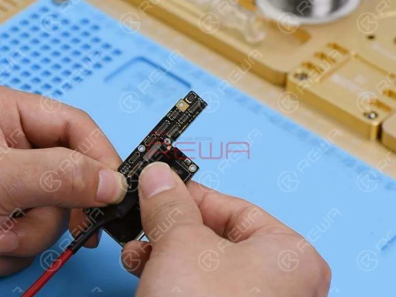
Touch the motherboard with one hand. The NAND flash chip and the area surrounding it are hot. Which indicates that rails on the area might have shorted. Since there are so many components on the hot area, we can locate the faulty component with the help of the Thermal Imager.
Thermal Imager
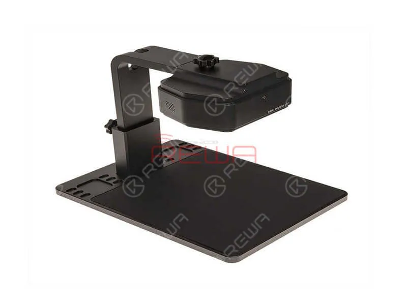
Features
This infrared thermal imager can detect the running temperature of motherboard chips, resistors and capacitors with the help of its built-in PC intelligent analysis software and intelligent algorithm.
This infrared thermal imager can help locate the current leakage/short-circuit position quickly.
It can greatly improve the efficiency and accuracy of your daily repair work with advanced technology.
Features a lifting bracket with removable design, the thermal imager is easy to assemble and carry.
You can also replace the visible lens of the thermal imager with electron-microscope lens and make it act as an electronic microscope.
The bracket can be adjusted by the knot to reach the best observation distance.
Put the motherboard under the Thermal Imager. Get the motherboard powered on. We can see clearly that C2647 is extremely hot. Judging by this, C2647 is probably damaged.
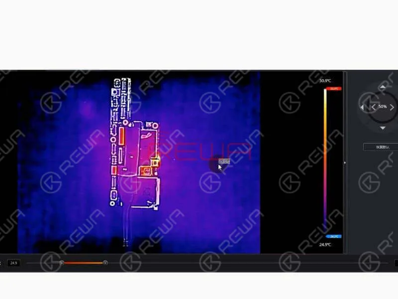
Let’s remove C2647 and run diode mode measurement of its bonding pad. The measured value is normal. We can confirm now that C2647 is damaged.
Troubleshooting
Let’s replace with a new capacitor and see how it works. Clean the bonding pad and apply some Paste Flux to the bonding pad. Then solder a new capacitor onto the board.
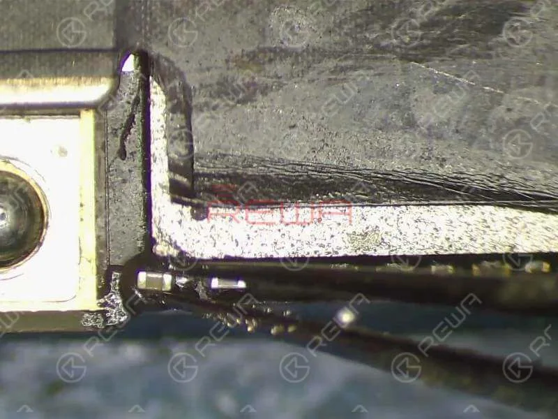
Reassemble And Test
Assemble the phone and test. The phone turns on normally.
Tools Used:
- Multifunctional PCB Holder for iPhone X
- Hot Air Gun Rework Station
- Integrated Mobile Phone Repair Platform
- Electron Microscope
- Thermal Imager
- iPhone Disassembling Tool Kits
You can also visit REWA YouTube Channel to check our video and learn how to fix iPhone X won’t turn on quickly and efficiently.
-
How To Fix iPhone XS Max Screen Flickering
iPhone display issues like screen flickering, white boxes, grey lines, red screen and blue screen are quite annoying. Luckily, you have found us. REWA chip-level motherboard repair service is aimed to help repair shops solve motherboard issues they could not handle by themselves. Today we will share a special repair case REWA LAB has helped with – iPhone XS Max abnormal screen display troubleshooting. Most importantly you need to understand the root causes of the screen flickering before undertaking any of remedies.
Here we have an iPhone XS Max motherboard from a client that comes with abnormal screen display.
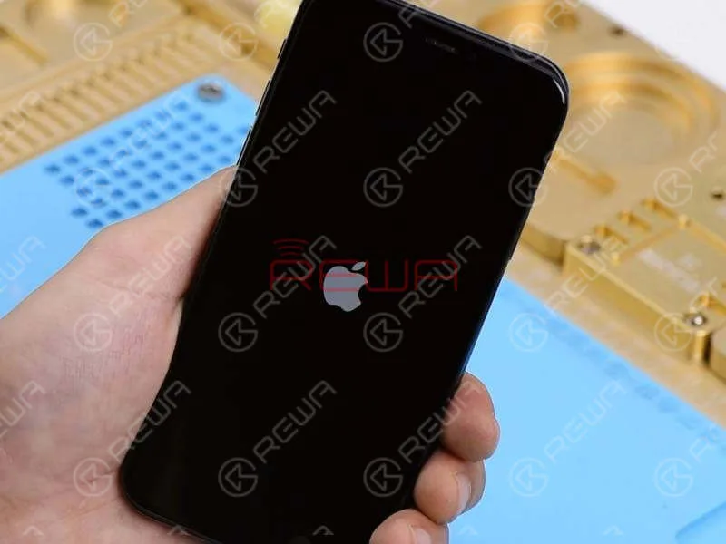
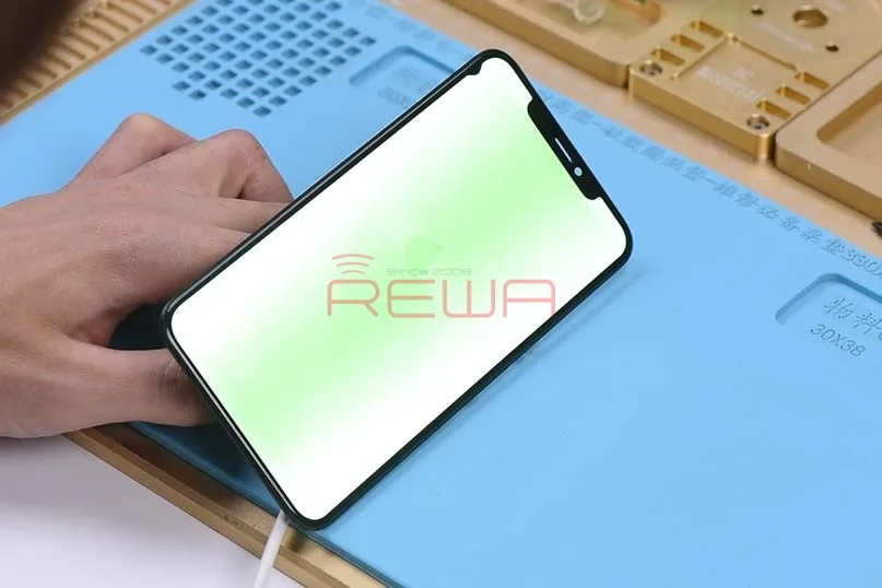
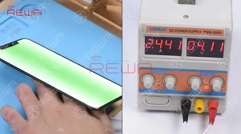
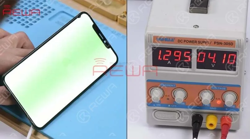
Connect an iPhone XS Max display assembly with the motherboard, and connect the battery connector with the DC Power Supply. Get the motherboard powered on with tweezers. We can see that the screen comes with abnormal display and the boot current is larger than normal value. However, the phone can access the activation screen. Judging by this, the display problem is probably related to the display circuit, the GPU circuit or the third space PCB.
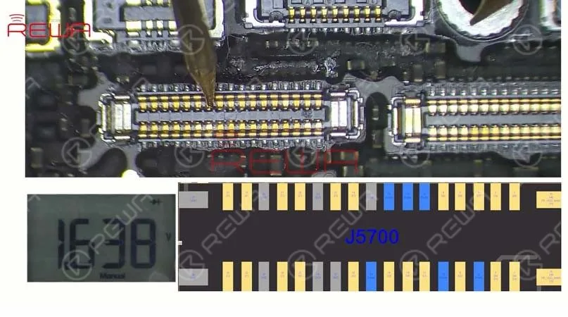
Let’s check the display circuit first. Run diode mode measurement of the display connector J5700. The measured value is normal. So the display problem has nothing to do with the display circuit.
Next, we need to check the GPU circuit. We need to separate the motherboard before the test. Place the motherboard on the specialized Heating Platform. 3 minutes later, pick up the upper layer with tweezers and then the lower layer.
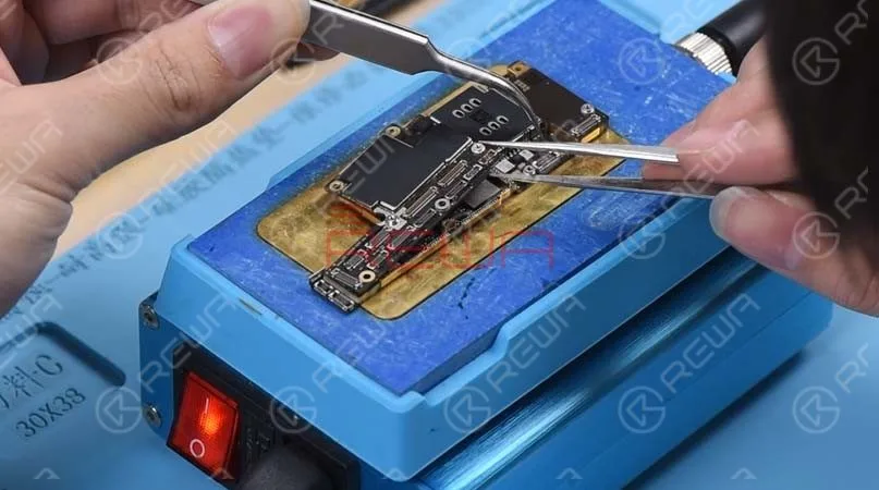
The problem remains the same. Which indicates that the display problem has nothing to do with the third space PCB.
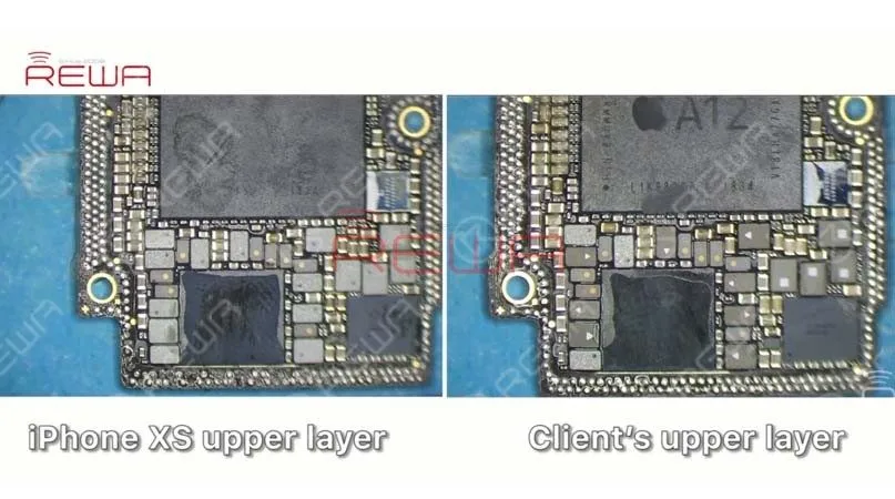
We need to continue with the GPU circuit. Attach the upper layer to the PCB Holder. Open REFOX and find the GPU circuit of iPhone XS Max. Compare the upper layer we are dealing with and the one on the bitmap. We find that the one we are dealing with is an iPhone XS upper layer, not an iPhone XS Max upper layer as described.
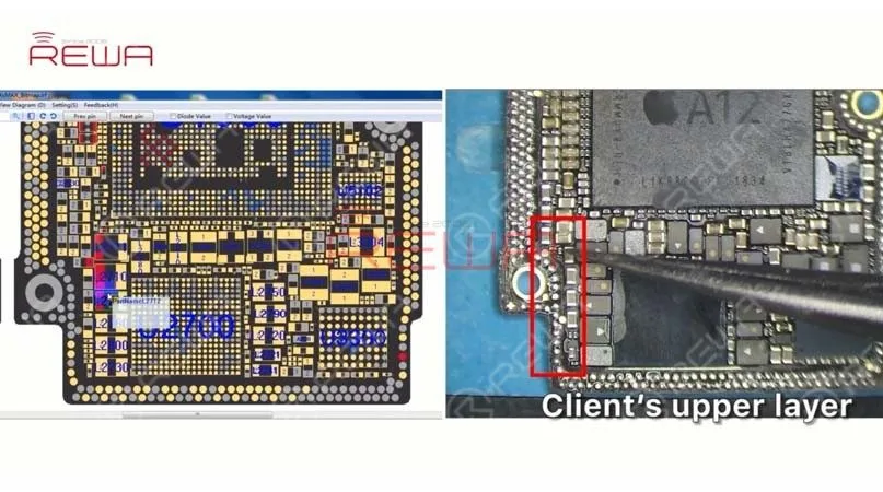
Upper Layer Comparison
Try to connect an iPhone XS display assembly with the upper layer and connect the battery connector with the DC Power Supply. Get the upper layer powered on with tweezers. The phone turns on normally with a normal display. The phone can access the activation screen and the boot current is also normal this time.
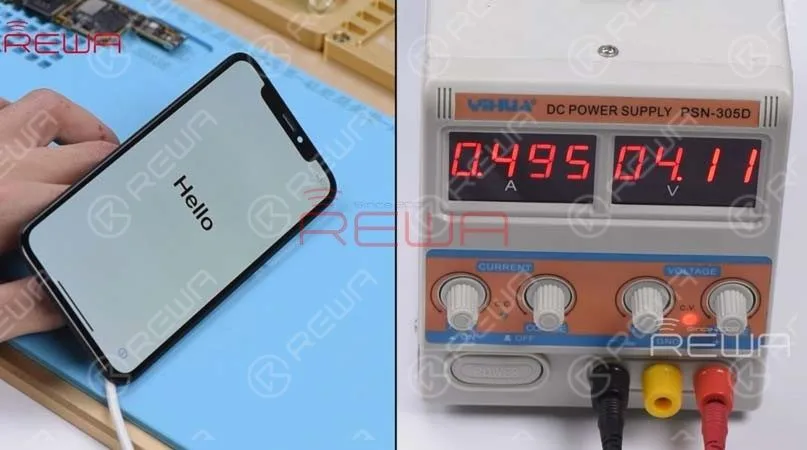
We can confirm now that our client soldered an iPhone XS upper layer onto an iPhone XS Max lower layer, and resulted in the abnormal screen display.
REWA Tips
REWA repair masters suggest that repair technicians keep a well-organized workspace in their daily repair work. You can develop a good habit by dividing your workspace into different areas according to different needs. For example, the repair area, the refurbishing area, tools/consumables, etc..
Tools and Parts Used In The Video:
-
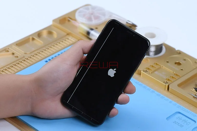
Fix iPhone X Keeps Restarting With Vertical Lines On The Screen
iPhone X features vertical lines on the screen and keeps restarting? iPhone keeps restarting and error 9, 14 and 40? How to narrow down the fault possibilities by ruling out one by one? How to confirm the fault and fix the problem? Follow us and learn how to fix this problem step by step.
First, we need to confirm if the fault has anything to do with the screen. Get a new iPhone X display assembly installed. The problem still remains the same as described earlier. We can confirm now that the fault is related to the motherboard.
The next thing we do is to confirm if the fault lies on the display circuit. Run diode mode measurement of the display connector, and measure the working voltage of the screen. All measured value is normal. Judging by this, the fault has nothing to do with the display circuit. It is probably related to PP_GPU_SRAM or CPU.
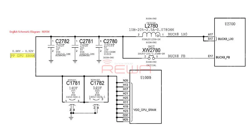
Again, let’s measure all the components on this circuit to narrow down the fault possibilities.
Still, we need to separate the motherboard before measurement. Then run diode mode measurement of components on the circuit. The measured value is normal. So we can rule out the possibility of shorted capacitors on the circuit. Which means the fault may be related to L2780, U2700 or U1000.
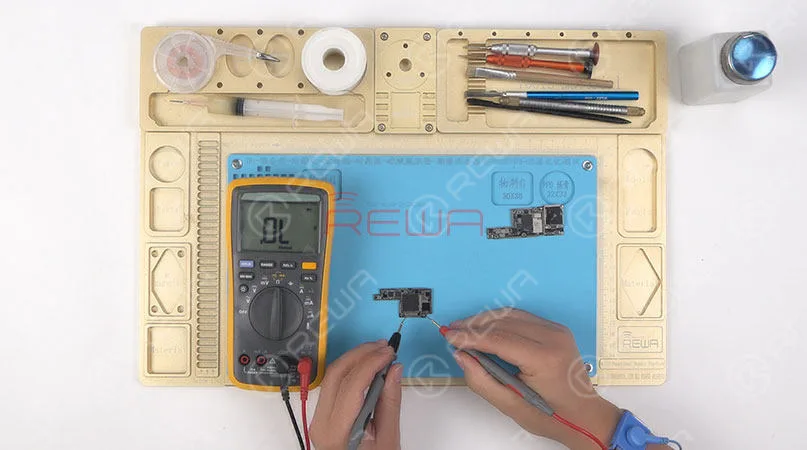
Let’s start with L2780 on the circuit. Remove L2780 with Hot Air Gun, and get a new inductor soldered. Test the motherboard with the help of the test fixture afterwards. The phone turns on with normal screen display. Problem solved. Now we need to solder the upper layer and the lower layer back together.
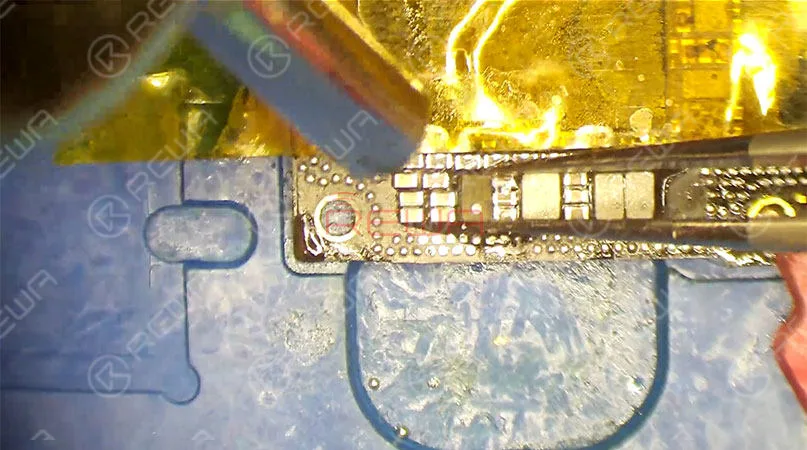
Reball the lower layer first. Continue to apply BGA Paste Flux to the third space PCB, and get the upper layer in position. Solder the two layers together with the Heating Platform. Now we can assemble the phone and test.
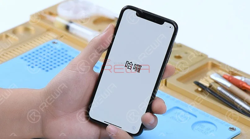
Press the power button to turn on the phone. Fault cleared.
For detailed steps, please visit here:
Tools Used:
- Hot Air Gun Rework Station – 990AD
- Soldering Iron Rework Station – 969A
- Integrated Mobile Phone Repair Platform
- Digital Multimeter Motherboard Soldering/Desoldering Rework Station for Apple iPhone X
- Needles BGA Flux Paste RMA
- Communication Maintenance Power Supply
- For Apple iPhone 4 – XS Max Power Supply Test Cable
- Logic Motherboard Test Fixture for iPhone X PCB Repair
REWA has dedicated itself to offering cell phone repair parts and tools for over 10 years. We offer iPhone X screen replacement parts in different quality grades, as well as other iPhone X replacement parts for wholesale. In REWA, everything comes with quality. Contact us or leave us your comment if you need our repair technique support. REWA screen and logic board repair guides:
-
Fix iPhone X Keeps Restarting – Logic Board Repair
The unique design and structure of its motherboard have made any repairs to iPhone X far more difficult than previous models. Especially logic board repairs. For every time. We need to desolder the double layer logic board before formal repair and resolder it back to after the repair was finished. Today we’ll fix the keep restarting issue by using our newly launched iPhone X motherboard soldering and desoldering rework station. Let’s begin our repair step by step.
Malfunction
Press the power button. And the Apple Logo appears on the screen(If you have met the issue about Apple logo, please check our special case for Fix iPhone 8 Stuck on Apple Logo). However, it keeps restarting. The motherboard of iPhone X is folded in half and soldered together. The upper layer mainly responsible for the phone boot up, and the lower layer mainly features baseband RF circuit. So the first thing we need to do is to detach the two layers from each other and check.
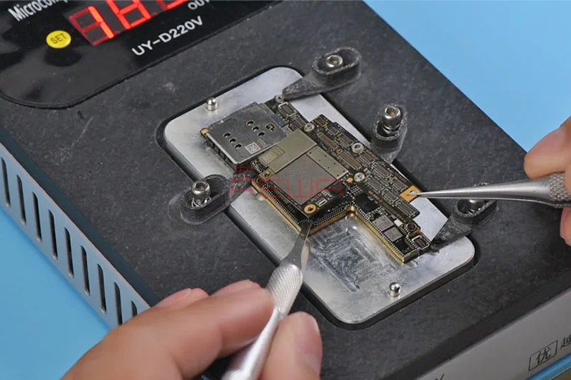
iPhone X logic board separation
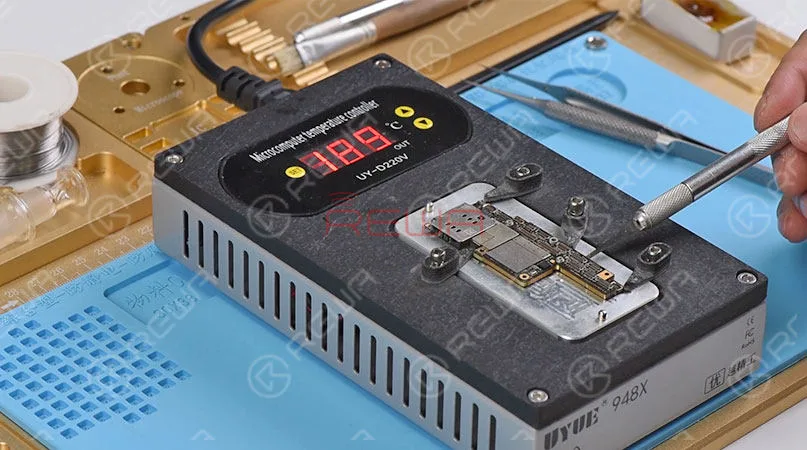
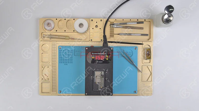
Here comes our iPhone X heating platform. Heat the double-layer motherboard on the platform with temperature of 190℃ for 1 minute. Remove the upper layer with Sculpture Knife and tweezers. Then, remove tins on the two layers respectively.
Malfunction Troubleshooting
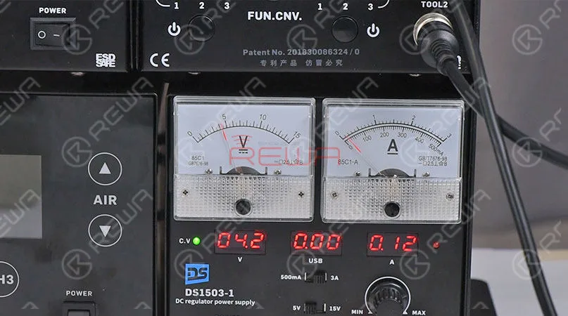
Connect the upper layer with display assembly. Then Connect it to DC Power Supply. And power up with trigger signal. The current reading on the ammeter is abnormal, which indicates that the fault is related to USB IC U6300. So we need to replace with a new USB IC and see how it works. Attach the upper layer to PCB Holder. Detach the USB IC from the upper layer with Hot Air Gun. We find that the USB IC has been replaced before and two empty pads have gone missing.
Repair
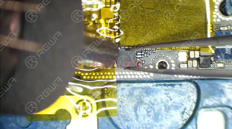
Let’s begin our repair. Remove tins on the bonding pad with rosin soaked Solder Wick. Then, apply some Paste Flux to the bonding pad. Get a new USB IC in position and solder with Hot Air Gun. Once done, clean with PCB Cleaner.
Test and check
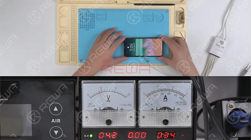
Again, let’s measure boot current of the upper layer. Current reading on the ammeter is normal. The phone can get access to the home screen normally. Fault cleared.
Resolder the double layer motherboard
Now we need to resolder the two layers together. Reball the lower layer first. Then attach the reballed lower layer to the heating platform. Apply some BGA Paste Flux to bonding pads on the lower layer. And get the upper layer in position with the temperature of 150℃ and heat the two layers for 1 minute on the heating platform. Once the two layers have been soldered together. Wait for the double-stacked motherboard to cool for 15 minutes. Check the motherboard carefully. The motherboard has been soldered perfectly.
Test and check again
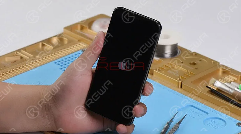
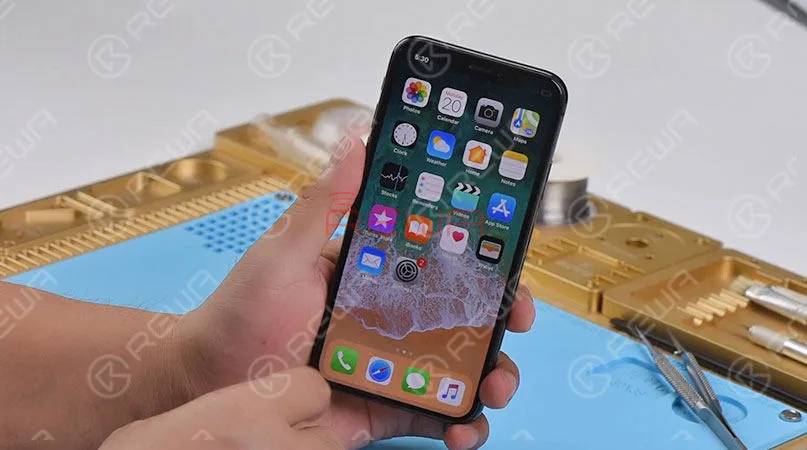
Now we can assemble the phone and test. Get the logic board and display assembly installed. Connect the battery and press power button. The phone turns on normally. iPhone X keeps restarting when turning on fixed perfectly.
Attaching the video for you for more details. For more repair information, please pay attention to REWA Official Youtube Channel.
Listing of the tools used. There is always one that you need or you are interested in. More cell phone replacement parts and tools please check REWA online store.
- iPhone X Motherboard Soldering/Desoldering Rework Station – RP200
- Integrated Mobile Phone Repair Platform
- Electron Microscope
- Digital Multimeter
- Stainless Steel BGA Scraper
- Straight Tweezer
- Paste Flux Solder Wick
- Heat-resisting Adhesive Tape – 5.0mm
- Anti-static Plastic Pry Bar Soft Brush
 English
 Español
 Français
 Deutsch
 Italiano