Tag: iphone motherboard

  • iPhone 13 Pro Motherboard Separation

    iPhone 13 Pro Motherboard Separation

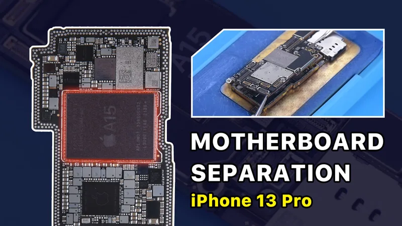
    In our last post, we did a teardown on iPhone 13 Pro. Today we will separate the motherboard of iPhone 13 Pro to share motherboard differences and repair difficulty.
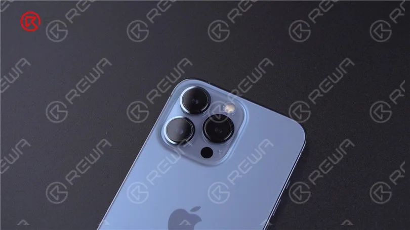
    iPhone 13 Pro Motherboard Separation – The Hottest CPU?

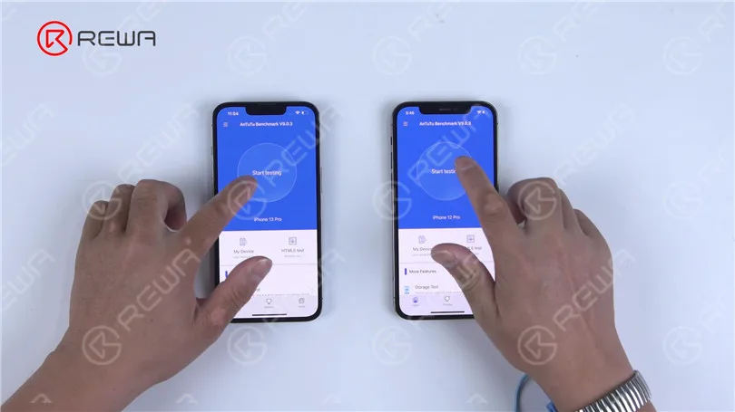
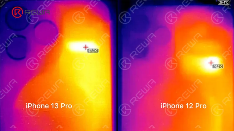
    In the first place, we benchmark iPhone 13 Pro and iPhone 12 Pro at the same time. Through LINCSEEK Infrared Thermal Camera, it is found that iPhone 13 Pro gets hotter than iPhone 12 Pro.

    iPhone 13 Pro can reach a maximum temperature of around 48 °C while the maximum temperature of iPhone 12 Pro is around 40 °C.
    iPhone 13 Pro Motherboard Separation – The Hottest CPU?
    iPhone 13 Pro Motherboard Separation – The Hottest CPU?

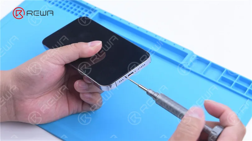
    Then we separate the motherboard of iPhone 13 Pro to view its interior structure and find out what has caused the overheating. In the meantime, we will walk you through how to separate and recombine the motherboard.
    iPhone 13 Pro Motherboard Separation – The Hottest CPU?

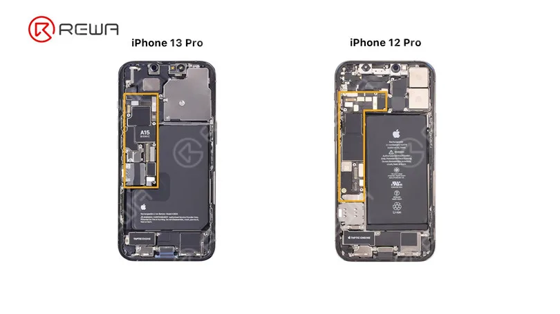
    iPhone 13 Pro’s motherboard is designed to be more compact to leave more room for the battery. Furthermore, the motherboard no longer uses an L-shaped design.
    iPhone 13 Pro Motherboard Separation – The Hottest CPU?

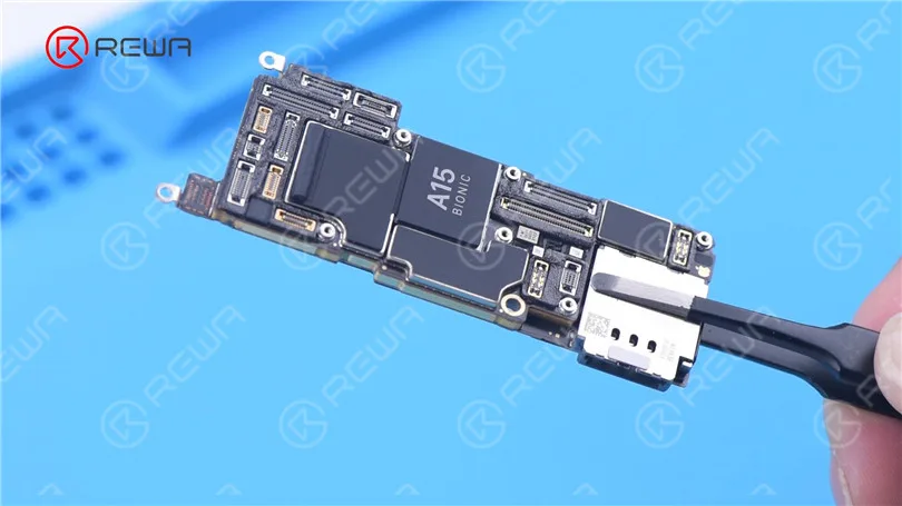
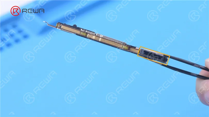
    Remove the motherboard. The double-layered design is still used. SIM card reader is not stand-alone and is welded to the motherboard.
    iPhone 13 Pro Motherboard Separation – The Hottest CPU?
    iPhone 13 Pro Motherboard Separation – The Hottest CPU?

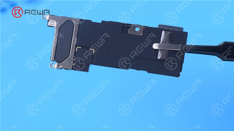
    For better heat dissipation, both sides of the motherboard are covered with thick heat dissipation tapes.
    iPhone 13 Pro Motherboard Separation – The Hottest CPU?

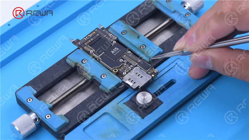
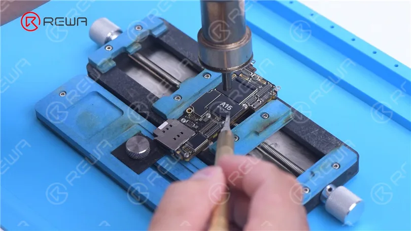
    Then we remove foam on the motherboard. Remove tape on the motherboard with Hot Air Gun at 100 °C. It can be seen that NAND is under the A15 tape.
    iPhone 13 Pro Motherboard Separation – The Hottest CPU?
    iPhone 13 Pro Motherboard Separation – The Hottest CPU?

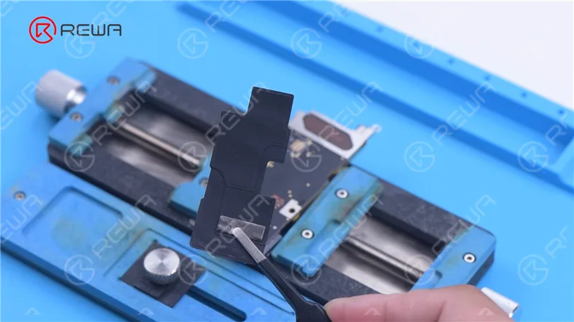
    Continue to remove tapes on the back of the motherboard. Heat dissipation tapes on the motherboard are reusable. Please do not damage the tapes during repair to avoid influencing the heat dissipation effect after assembly.
    iPhone 13 Pro Motherboard Separation – The Hottest CPU?

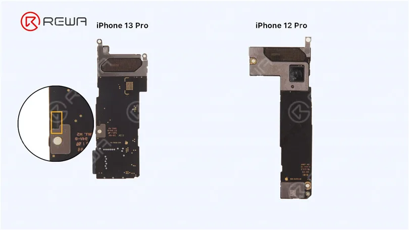
    We found that the back of iPhone 13 Pro’s signal board has components. Please pay attention not to damage the components while separating.
    iPhone 13 Pro Motherboard Separation – The Hottest CPU?

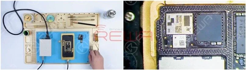
    Since the heating platform for iPhone 13 Pro has not come out yet, we use a universal heating platform at 170 °C for separation.

    Because the middle layer of iPhone 13 lineup’s motherboard still uses middle-temperature Solder Paste for soldering.

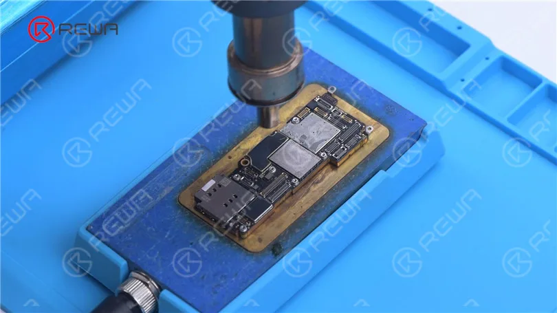
    Add heat with Hot Air Gun at 330 °C around the motherboard, when the temperature of the Heating Platform reaches 150 °C. As the logic board becomes loose, remove the logic board with tweezers.

    Please do not damage surrounding components while removing.
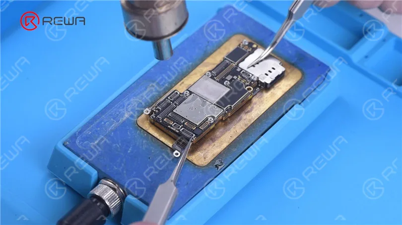
    iPhone 13 Pro Motherboard Separation – The Hottest CPU?

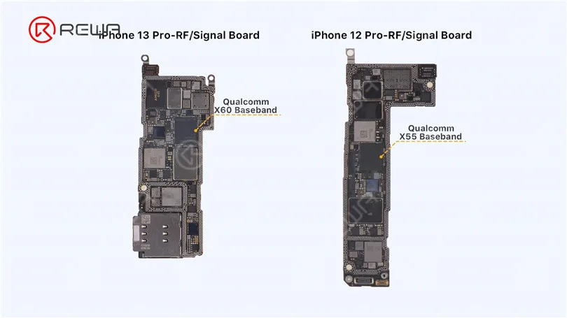
    The CPU is stacked with the baseband which is bad for motherboard heat dissipation.
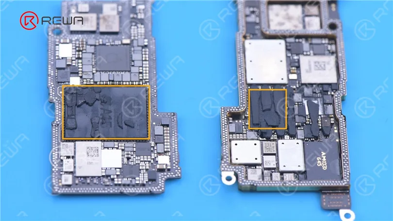
    iPhone 13 Pro Motherboard Separation – The Hottest CPU?

    Then we remove thermal grease on the chips.
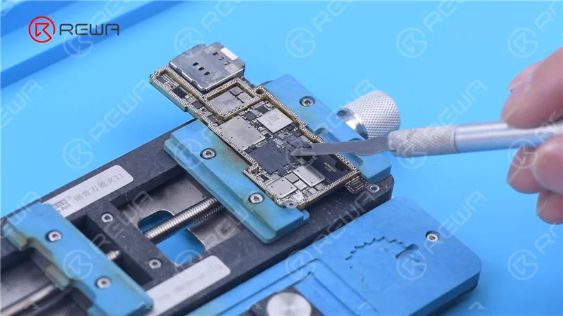
    iPhone 13 Pro Motherboard Separation – The Hottest CPU?

    The size of A15 has increased a lot, which makes CPU desoldering more difficult.
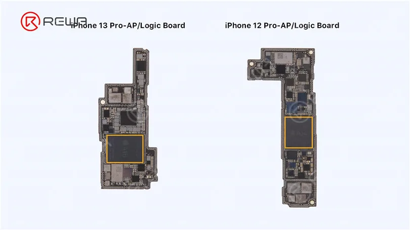
    iPhone 13 Pro Motherboard Separation – The Hottest CPU?

    The iPhone 13 Pro’s baseband CPU has been upgraded to the Qualcomm X60. It is believed that the phone signal will be more stable than previous models. 
    iPhone 13 Pro Motherboard Separation – The Hottest CPU?

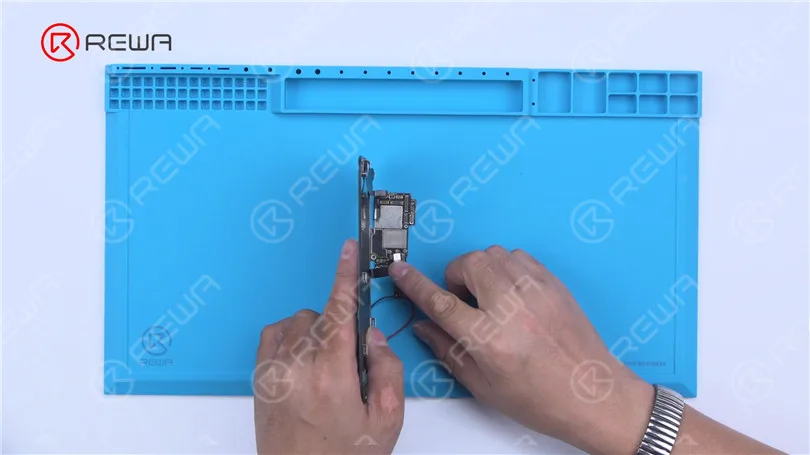
    Then we see if a single logic board of iPhone 13 Pro can trigger the boot-up. Power the logic board with a Direct Current Supply.

    Connect the display. Trigger the boot-up with tweezers.

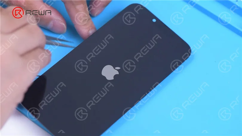
    We can see that iPhone 13 Pro took longer to trigger the boot-up than previous models.

    It takes 8-10 seconds for the Apple logo to appear on the screen. This may be caused by the system.
    iPhone 13 Pro Motherboard Separation – The Hottest CPU?
    iPhone 13 Pro Motherboard Separation – The Hottest CPU?

    Then we recombine the signal board with the logic board.

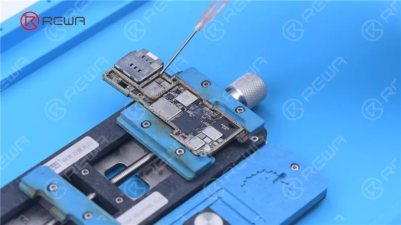
    Apply some Paste Flux to the bonding pads of the signal board.

    To better clean tin subsequently, apply some low-temperature Solder Paste to neutralize the temperature of the bonding pads.
    iPhone 13 Pro Motherboard Separation – The Hottest CPU?

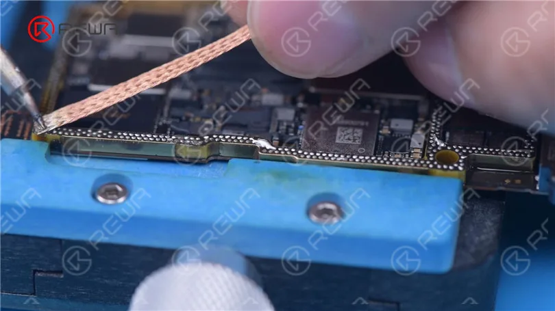
    Clean the bonding pads with Soldering Iron at 380 °C and solder wick.

    Apply solder paste to the bonding pads of the logic board.

    Please do not affect surrounding components while applying solder paste.

    This should also be noted while using Soldering Iron to remove tin.
    iPhone 13 Pro Motherboard Separation – The Hottest CPU?

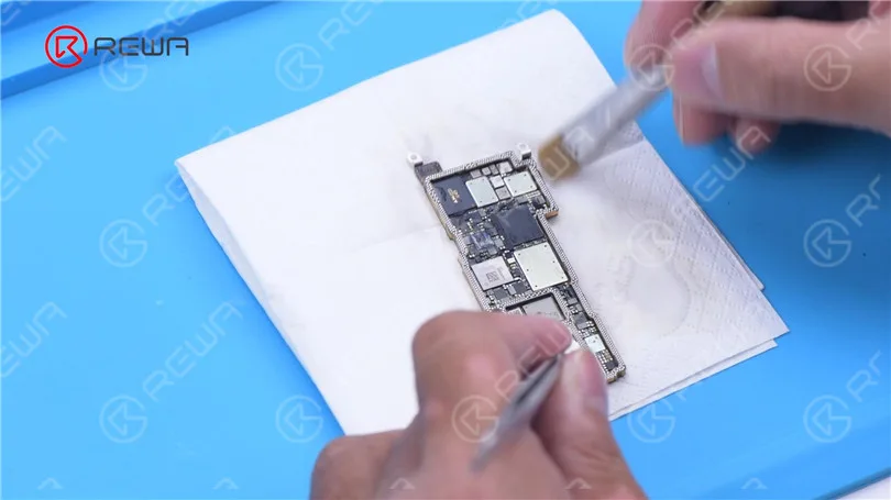
    Clean the bonding pads with PCB Cleaner.
    iPhone 13 Pro Motherboard Separation – The Hottest CPU?

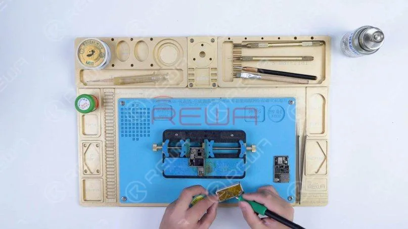
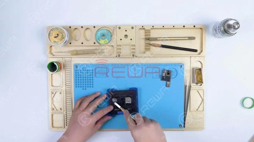
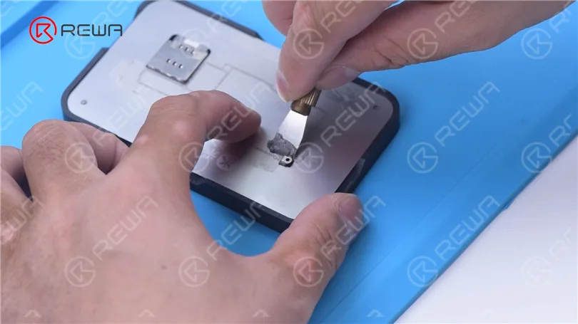
    Then we reball the signal board. Attach the signal board to the Reballing Platform.

    Put the reballing stencil in position. Apply middle-temperature Solder Paste evenly.
    iPhone 13 Pro Motherboard Separation – The Hottest CPU?

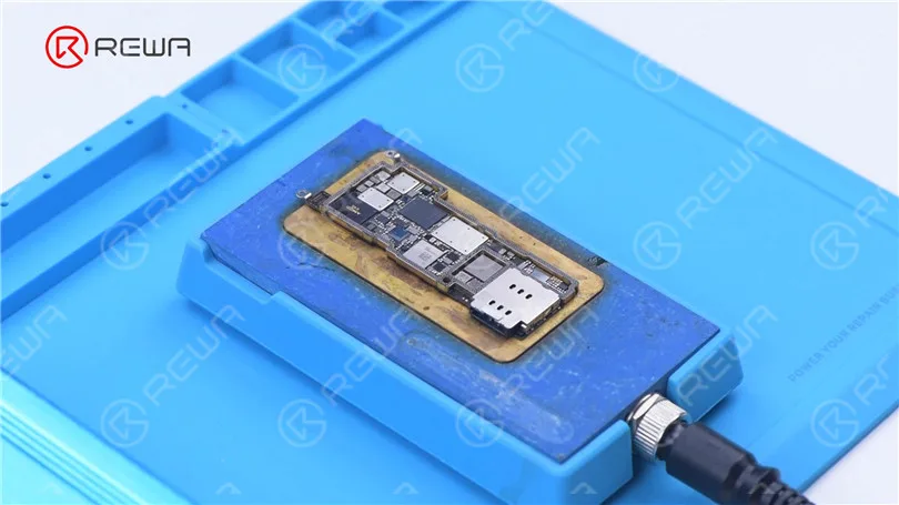
    Remove the reballing stencil. Put the signal board on the Heating Platform to heat.

    After the solder balls are formed, cool the signal board.
    iPhone 13 Pro Motherboard Separation – The Hottest CPU?

    Apply some Paste Flux to the bonding pads.

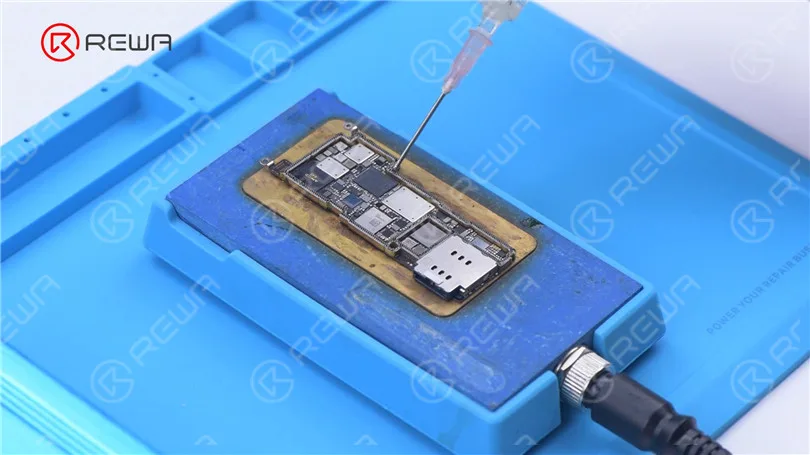
    Align the logic board with the signal board.

    Keep heating with the Heating Platform at 170 °C.

    Add heat around the motherboard with Hot Air Gun at 330 °C.
    iPhone 13 Pro Motherboard Separation – The Hottest CPU?
    iPhone 13 Pro Motherboard Separation – The Hottest CPU?

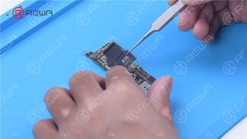
    After the motherboard has cooled, detach the motherboard.

    Reattach foam and heat dissipation tapes to the motherboard.
    iPhone 13 Pro Motherboard Separation – The Hottest CPU?

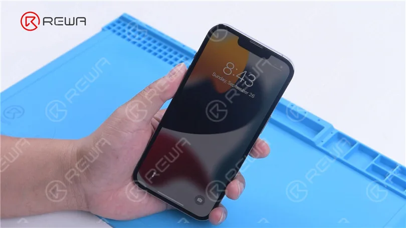
    Install the motherboard for testing. The phone turns on normally.
    iPhone 13 Pro Motherboard Separation – The Hottest CPU?

    In summary, through this separation, it is found that iPhone 13 Pro still has a double-layered motherboard.

    The motherboard has some changes in appearance but there is little change in the main chip distribution.

    Additionally, the CPU and baseband are stacked, which not only increases the difficulty of repair but also makes the motherboard heat up easily.

    Under certain conditions, the motherboard is more likely to have problems.
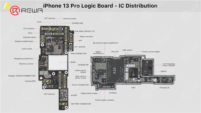
    For your reference, this is the motherboard chip distribution diagram of iPhone 13 Pro from iRepair.
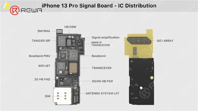
    iPhone 13 Pro Motherboard Separation – The Hottest CPU?
    iPhone 13 Pro Motherboard Separation – The Hottest CPU?
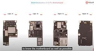
  • iPhone 11 Pro Motherboard Chips Distribution | REWA Academy

    iPhone 11 Pro Motherboard Chips Distribution | REWA Academy

    Some repair technicians repair motherboards according to experience and thus the repair result cannot be guaranteed. Only when you comprehend the phone working principles can the motherboard problems be fully resolved. REWA Academy is about to launch the iPhone 11 Pro motherboard repair online course, providing technicians with systematic motherboard repair knowledge.

  • Troubleshooting iPhone 11 Pro Max No Service

    Troubleshooting iPhone 11 Pro Max No Service

    Recently, many repair technicians reported that they had received lots of iPhone 11 Pro Max with no service.

    Worse still, the fault could not be eliminated after replacing the signal board.

    Based on experience, REWA LAB technicians preliminarily conclude that the fault is likely on the signal pads of the logic board. Let’s check it out!

    Step 1: Fault analysis

    The motherboard has been repaired once.

    The original fault was no service but with the baseband modem firmware.

    The previous repair welded the baseband CPU and baseband EPROM to a good signal board.

    But the phone still had no service. It can be preliminarily judged that there are two possible faults.

    One is the damage of baseband CPU and baseband EPROM.

    The other is the damage of circuits related to the signal on the logic board.

    First of all, we install the motherboard on the phone to test.

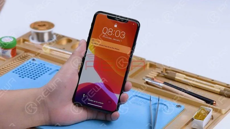
    The phone turns on normally but has no service.
    First of all, we install the motherboard on the phone to test. The phone turns on normally but has no service.

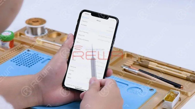
    Go to Settings, General, and About. We can see that the phone has no modem firmware.
    Go to Settings, General, and About. We can see that the phone has no modem firmware.

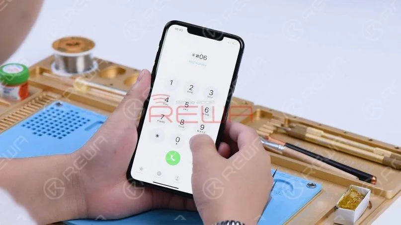
    Dial *#06# and the IMEI can’t be seen.

    Dial *#06# and the IMEI can’t be seen.

    The phone used to have modem firmware but now no longer has it. The cause may be related to pseudo soldering of the motherboard middle layer or damage of the baseband CPU and baseband EPROM.

    Step 2: Motherboard separation and troubleshooting

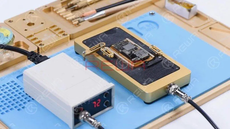
    Then we separate the motherboard to locate the faulty component. Put the motherboard on the Heating Platform and set the temperature to 185℃.

    Then we separate the motherboard to locate the faulty component. Put the motherboard on the Heating Platform and set the temperature to 185℃.

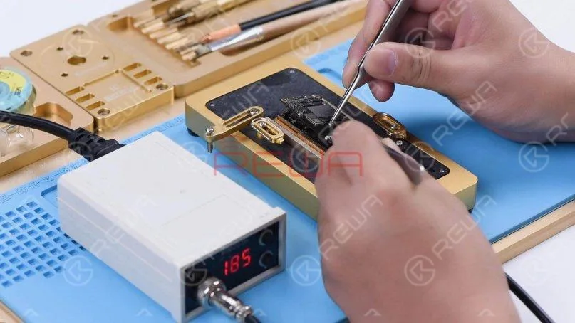
    When the temperature has risen to 185℃, remove the logic board with tweezers.
    When the temperature has risen to 185℃, remove the logic board with tweezers.

    Turn the power off and remove the signal board.

    Turn the power off and remove the signal board.

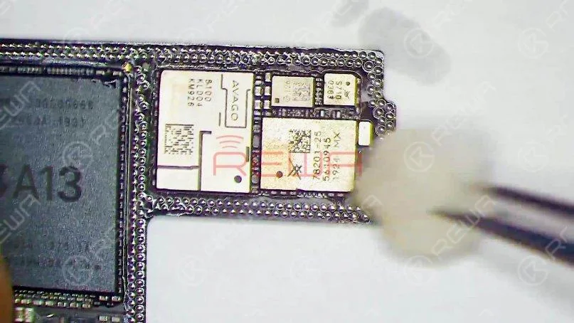
    Clean the logic board with PCB Cleaner.

    Since the signal board has been replaced, we need to check the logic board first.

    According to the test result, we can later determine whether the baseband CPU and EPROM are damaged.

    Clean the logic board with PCB Cleaner. Since the signal board has been replaced, we need to check the logic board first. According to the test result, we can later determine whether the baseband CPU and EPROM are damaged.

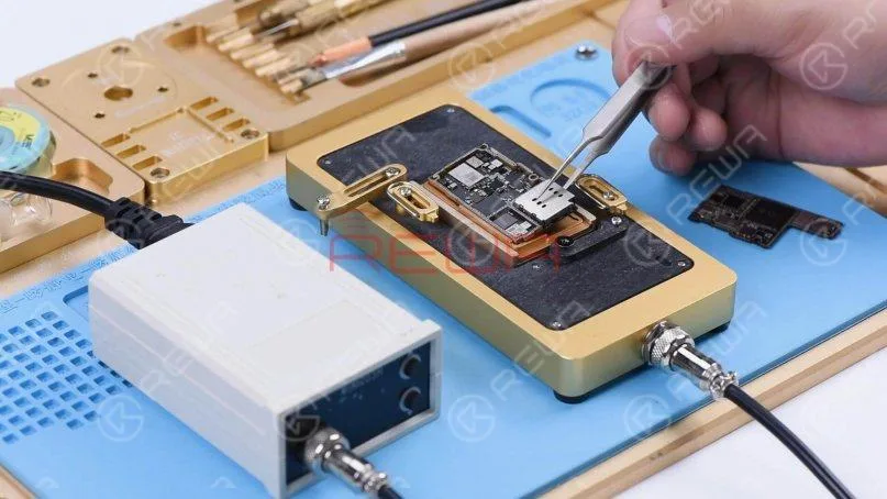
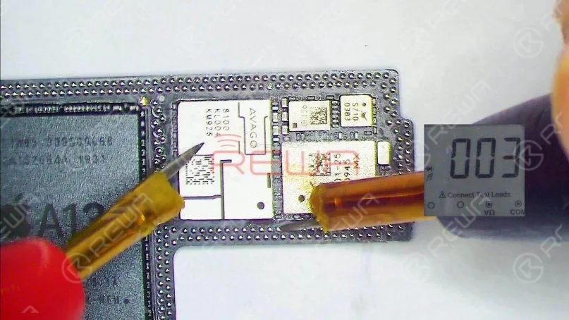
    Run diode mode measurement of the signal pads on the middle layer of the logic board.

    When measuring pin 131, the diode value is 003. The normal value should be around 400.

    Run diode mode measurement of the signal pads on the middle layer of the logic board. When measuring pin 131, the diode value is 003. The normal value should be around 400.

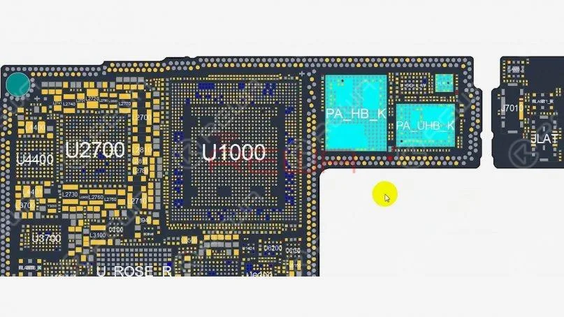
    Open the bitmap and many associated components are seen on the circuit.

    Open the bitmap and many associated components are seen on the circuit.

    Then we locate the faulty component with rosin detecting.

    Dip rosin with Soldering Iron at 365℃ and smoke some rosin on associated components.
    Then we locate the faulty component with rosin detecting. Dip rosin with Soldering Iron at 365℃ and smoke some rosin on associated components.

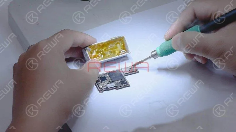
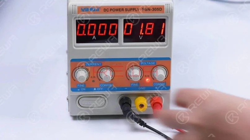
    Set the direct current supply to 1.8V. Connect the positive and negative anode of the direct current supply with multimeter probes.
    Set the direct current supply to 1.8V. Connect the positive and negative anode of the direct current supply with multimeter probes.

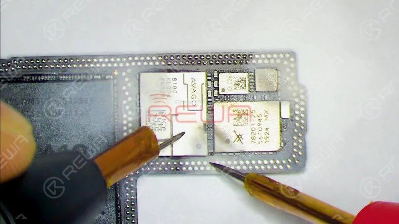
    Then connect the black probe to the ground and connect the red probe to pin 113 on the logic board. We can see rosin on a capacitor has melted.

    It indicates that the component is damaged. This circuit has multiple filter capacitors, so we can directly remove the damaged capacitor.
    Then connect the black probe to the ground and connect the red probe to pin 113 on the logic board. We can see rosin on a capacitor has melted. It indicates that the component is damaged. This circuit has multiple filter capacitors, so we can directly remove the damaged capacitor.

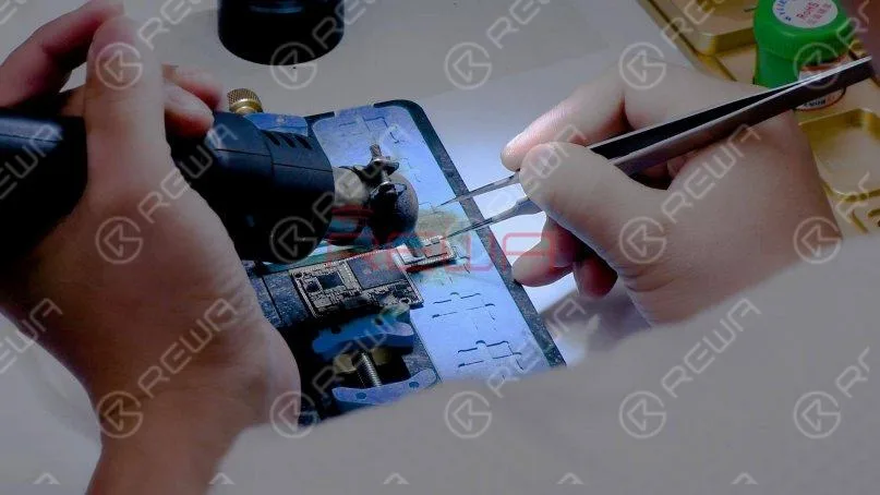
    Remove the capacitor with Hot Air Gun at 350℃ and airflow 3.

    Remove the capacitor with Hot Air Gun at 350℃ and airflow 3.

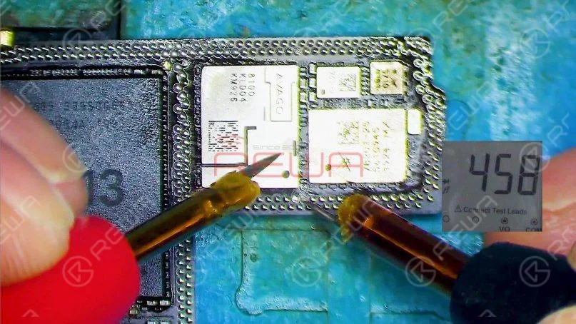
    Measure the logic board again after it has cooled. The diode value returns to a normal value of 458.
    Measure the logic board again after it has cooled. The diode value returns to a normal value of 458.

    Step 3: Motherboard restoration

    Next, we need to restore the motherboard.

    Firstly, we need to remove tin on the bonding pad of the motherboard.

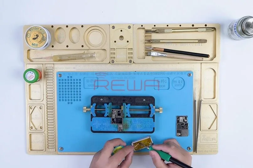
    Smear rosin with Soldering Iron at 365℃ and solder-wick to remove tin on the bonding pad.

    Next, we need to restore the motherboard. Firstly, we need to remove tin on the bonding pad of the motherboard. Smear rosin with Soldering Iron at 365℃ and solder-wick to remove tin on the bonding pad.

    Remove tin on the signal board with the same method.

    After that, clean the logic board and signal board with PCB Cleaner.

    Next, attach the signal board to the Reballing Platform and put the Reballing Stencil in position.

    Apply a layer of medium-temperature Solder Paste evenly.
    Remove tin on the signal board with the same method. After that, clean the logic board and signal board with PCB Cleaner.Next, attach the signal board to the Reballing Platform and put the Reballing Stencil in position. Apply a layer of medium-temperature Solder Paste evenly.

    After reballing, put the signal board on the 185℃ Heating Platform to heat.

    When the solder balls are formed, turn the power off and cool the signal board.
    After reballing, put the signal board on the 185℃ Heating Platform to heat. When the solder balls are formed, turn the power off and cool the signal board.

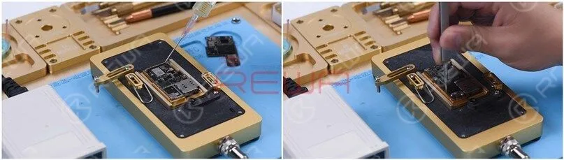
    Apply some Paste Flux to the bonding pad of the signal board and align the logic board with the signal board.
    Apply some Paste Flux to the bonding pad of the signal board and align the logic board with the signal board.

    Keep heating the motherboard on the 185℃ Heating Platform.

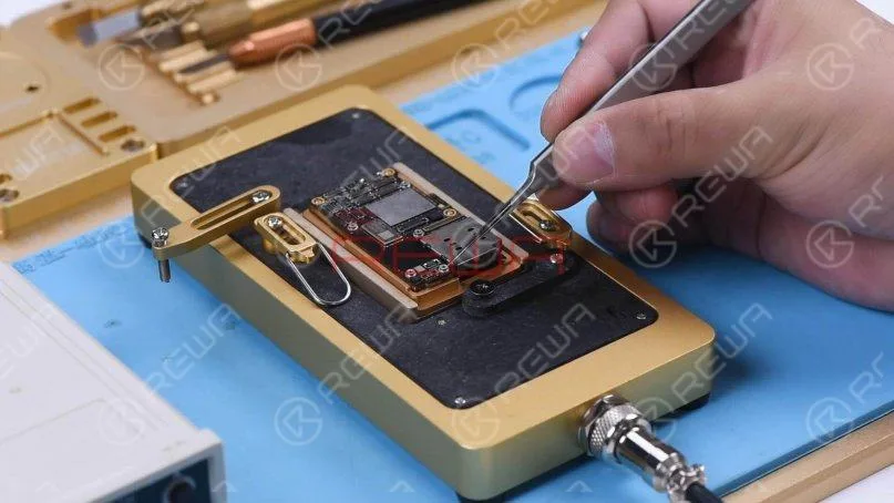
    Push the logic board gently with tweezers and the logic board can return to the previous position.

    It shows that the motherboard has completed soldering.

    Keep heating the motherboard on the 185℃ Heating Platform. Push the logic board gently with tweezers and the logic board can return to the previous position. It shows that the motherboard has completed soldering.

    Turn the power off and cool the motherboard for 5 minutes.

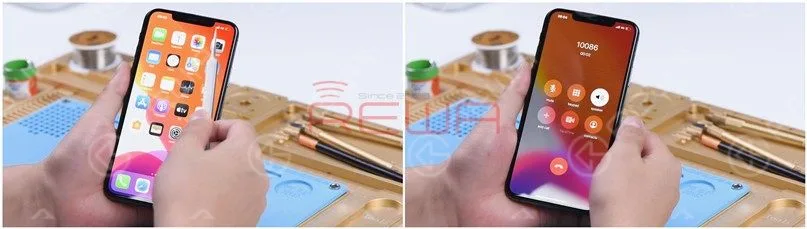
    Then remove the motherboard and install it on the phone.

    The phone turns on normally and the 4G signal can be received.

    A phone call can also be made. The fault is cleared.

    Turn the power off and cool the motherboard for 5 minutes. Then remove the motherboard and install it on the phone. The phone turns on normally and the 4G signal can be received. A phone call can also be made. The fault is cleared.

    Summary

    The iPhone 11 Pro Max has been repaired once and still has no service after the baseband CPU and EPROM has been welded to a good signal board.

    It can be preliminarily judged that there are two possible faults. One is the damage of baseband CPU and baseband EPROM. The other is the damage of circuits related to the signal on the logic board.

    Through measuring the signal pads on the logic board and rosin detecting, a capacitor was found damaged.

    After removing the capacitor, the no service fault was cleared.

    We can rule out the possibility of baseband CPU and EPROM fault since the no service fault was eliminated after repairing the logic board.

    If you want to study more, please feel free to visit our academy for repair courses.