Tag: iPhone 8 Plus

  • How to Fix iPhone 8 Plus 2x Camera Not Working

    How to Fix iPhone 8 Plus 2x Camera Not Working

    The iPhone 8 Plus, launched in September 2017, has long been praised for its impressive dual-camera setup, allowing users to capture stunning photos with both 1x and 2x options. However, many owners have faced frustrating issues with the iPhone 8 Plus 2x camera not working, while the rest of the phone functions smoothly. If you’re among those experiencing this problem, don’t worry — you’re not alone! In this article, we’ll explore the common causes behind the malfunction of the 2x camera on your iPhone 8 Plus and provide step-by-step guidance on how to troubleshoot and repair the issue effectively.
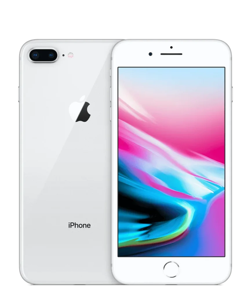
    iPhone 8 plus silver color

    Phone Details

    Model: iPhone 8 Plus

    Announced: 2017, September 12

    Defect Phenomenon

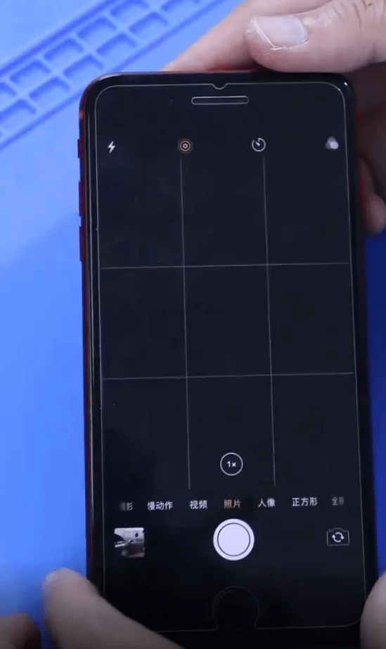
    The phone boots up normally, but the 2x camera does not function. Upon further testing, the 2x camera works after replacing the rear camera module, but switching to the 1x camera mode causes the camera to stop working. The 1x camera fails to turn on, indicating a potential issue with the motherboard.

    Troubleshooting

    1: Initial Steps
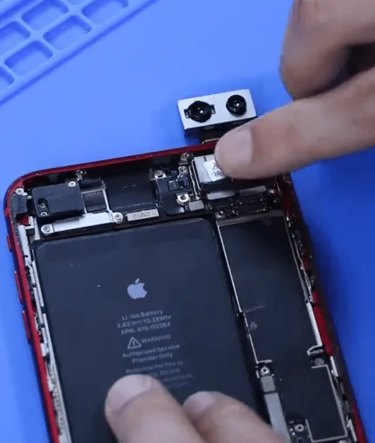
    • Disassemble the phone and remove the rear camera module.
    • Replace the module with a new one and test the camera functions.
    • The 2x camera works correctly, but the 1x camera still fails to turn on, suggesting a motherboard-related issue.

    2: Motherboard Inspection
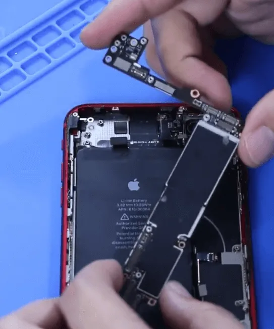
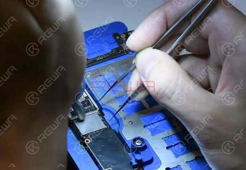
    • Remove the motherboard and examine it carefully under a microscope.
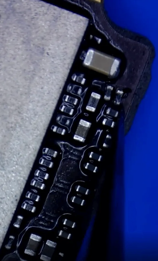
    • Notice that some small resistors have been previously replaced, but the shielding cover remains intact, indicating the chips under the cover have not been repaired.

    3: Identify Potential Causes
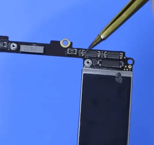
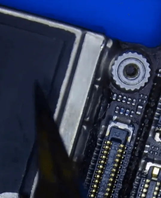
    • The iPhone 8 Plus features dual rear cameras: the left is the 2x camera, and the right is the 1x camera.
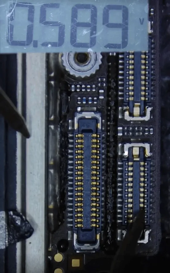
    • Since the 1x camera is not functioning, focus on checking the diode values on the right connector using a multimeter.

    Measure the diode values on the coupling capacitor to the CPU, finding that all values are within normal range, suggesting the CPU is not the issue.

    Repair Process

    1: Power Supply Testing
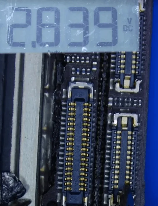
    • Measure the power supplies for the camera by connecting the motherboard to a DC power supply.
    • Trigger the motherboard to boot using tweezers, and measure the voltages using a multimeter.

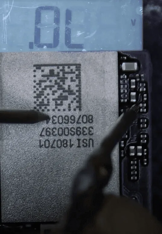
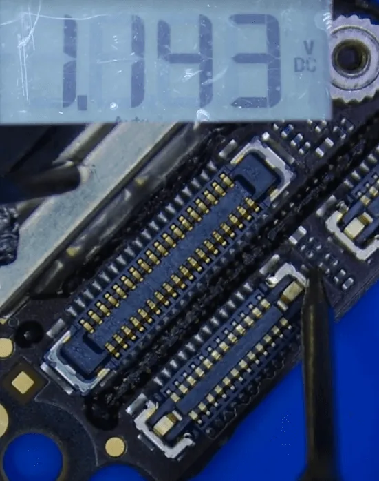
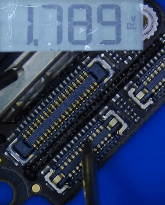
    Confirm that all three required voltages (2.8V, 1.1V, 1.8V) for the 1x camera are present, indicating the camera power supply IC is likely functioning correctly.

    2: Replace the Coupling Capacitors
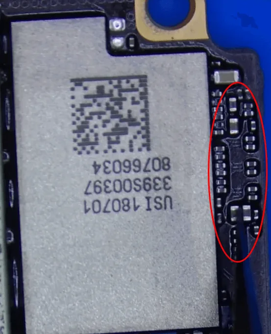
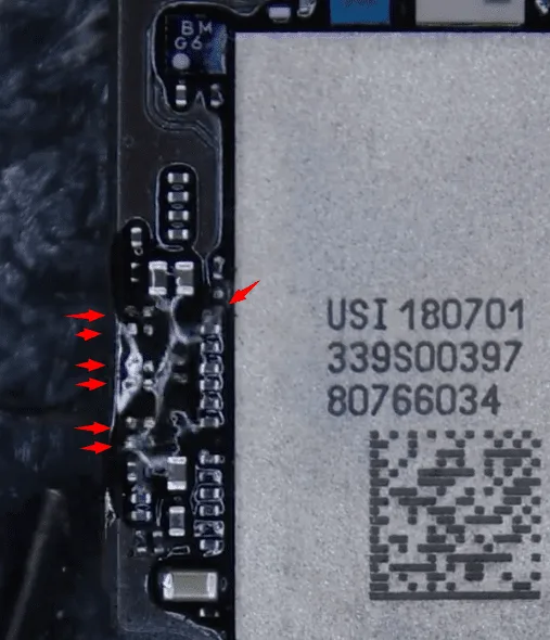
    • Remove the seven coupling capacitors responsible for the camera’s function.
    • Solder back seven new coupling capacitors with identical specifications.

    During the soldering process, carefully control the hot air gun’s heating temperature and time to avoid damaging nearby components like the Wi-Fi chip.

    3: Reassemble and Test
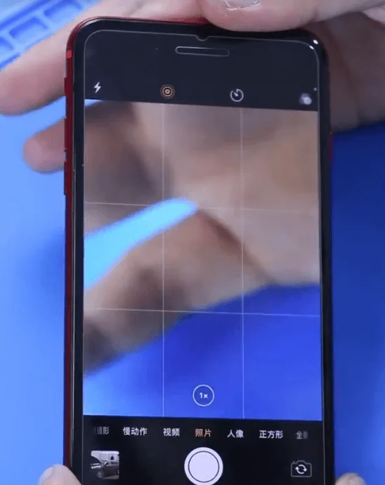
    iphone 8 plus 2x camera repair
    • Reassemble the phone and reinstall the rear camera module.
    • Test the camera functions again, confirming that both the 1x and 2x cameras now work perfectly.

    Conclusion

    The issue with the 1x camera not functioning was resolved by replacing the coupling capacitors on the motherboard. Careful attention to the power supply and proper soldering techniques ensured that the iPhone 8 Plus 2x camera not working issue were fully restored.
  • Fix iPhone 8 Plus WiFi Not Working | 3-Step-Guide

    Fix iPhone 8 Plus WiFi Not Working | 3-Step-Guide

    In most cases, iPhone grayed-out WiFi switch issue is caused by damage of the WiFi module. And we need to replace the WiFi module to fix the problem.

    What’s more, the WiFi module is bound up with WiFi address stored in the NAND flash chip.

    When replacing the WiFi module, there is one indispensable step as WiFi unbinding.

    How to successfully replace the WiFi module and complete WiFi unbinding in four steps? Follow our repair guide now!

    Problem

    Press the power button to turn on the phone.

    The phone turns on normally.

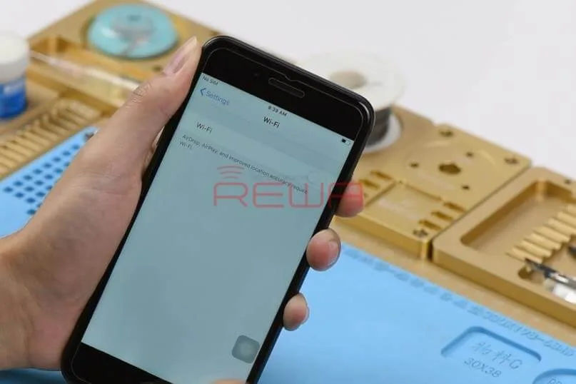
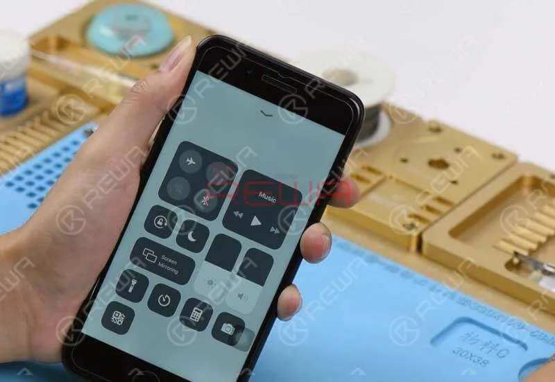
    Go to Settings>WiFi. The WiFi switch cannot be toggled.
    Press the power button to turn on the phone. The phone turns on normally. Go to Settings>WiFi. The WiFi switch cannot be toggled.

    Take apart the phone and remove the display assembly.

    Disconnect the battery and take out the logic board. Then tear off the shielding sticker.

    Diagnosis

    The first thing we do is to check working conditions of the WiFi module.

    Run diode mode measurement of the three rails of power supply.

    Nothing goes wrong.

    Judging by this, WiFi relevant circuits have not open-circuited or short-circuited.
    The first thing we do is to check working conditions of the WiFi module. Run diode mode measurement of the three rails of power supply. Nothing goes wrong. Judging by this, WiFi relevant circuits have not open-circuited or short-circuited.

    Continue to measure the working voltage of the WiFi module.

    Connect the battery connector with the DC Power Supply and short Pin 8 of J4300 to the ground with tweezers.

    The system will then detect power button press.

    Switch the Multimeter to the voltage mode and run voltage measurement of the three rails of power supply.

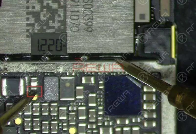
    The measured voltage value of SR_LVX_W is 1.22V, which is abnormal. Normal voltage value should be 1.35V.
    Continue to measure the working voltage of the WiFi module. Connect the battery connector with the DC Power Supply and short Pin 8 of J4300 to the ground with tweezers. The system will then detect power button press. Switch the Multimeter to the voltage mode and run voltage measurement of the three rails of power supply. The measured voltage value of SR_LVX_W is 1.22V, which is abnormal. Normal voltage value should be 1.35V.

    SR_LVX_W is the internal power supply circuit of the WiFi module.

    The abnormal voltage value indicates that the WiFi module has malfunctioned.

    So we need to replace with a new WiFi module.

    Troubleshooting

    Attach the logic board to the PCB Holder.

    Remove black adhesive around the WiFi module.

    Then heat with the Hot Air Gun and pry up the WiFi module with the Sculpture Knife.

    Continue to apply some Paste Flux to the bonding pad.

    And then some middle-temperature solder paste.

    Heat with the Soldering Iron to neutralize the melting temperature on the bonding pad and clean the bonding pad with rosin soaked Solder Wick.

    Clean with PCB Cleaner afterwards.
    Continue to apply some Paste Flux to the bonding pad. And then some middle-temperature solder paste. Heat with the Soldering Iron to neutralize the melting temperature on the bonding pad and clean the bonding pad with rosin soaked Solder Wick. Clean with PCB Cleaner afterwards.

    Note 

    The WiFi module is bound up with WiFi address stored in the NAND flash chip.

    When replacing the WiFi module, here we have one indispensable step as WiFi unbinding.

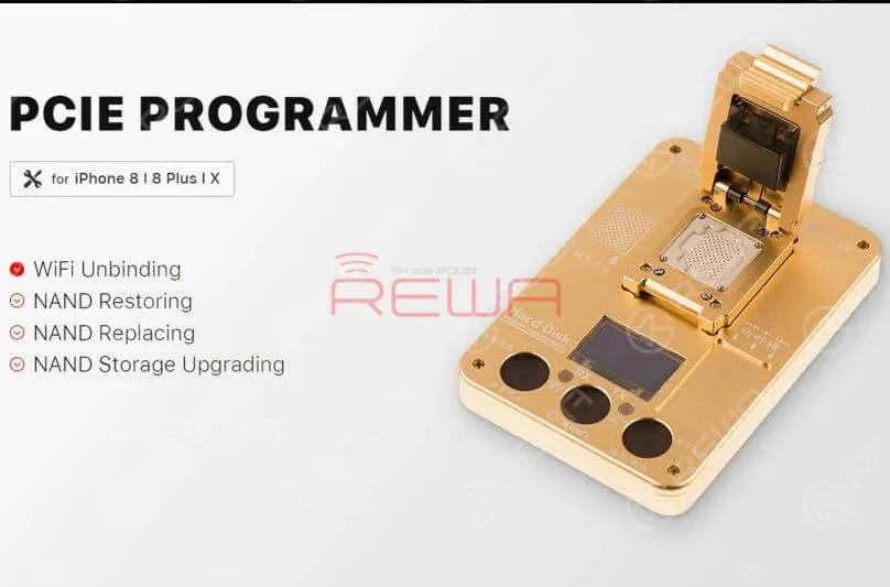
    A PCIE programmer is needed in this step.

    PCIE NAND Flash Memory Chip Programmer For iPhone8/8 Plus/X
    The WiFi module is bound up with WiFi address stored in the NAND flash chip. When replacing the WiFi module, here we have one indispensable step as WiFi unbinding. A PCIE programmer is needed in this step.PCIE NAND Flash Memory Chip Programmer For iPhone8/8 Plus/X

    WiFi Unbinding

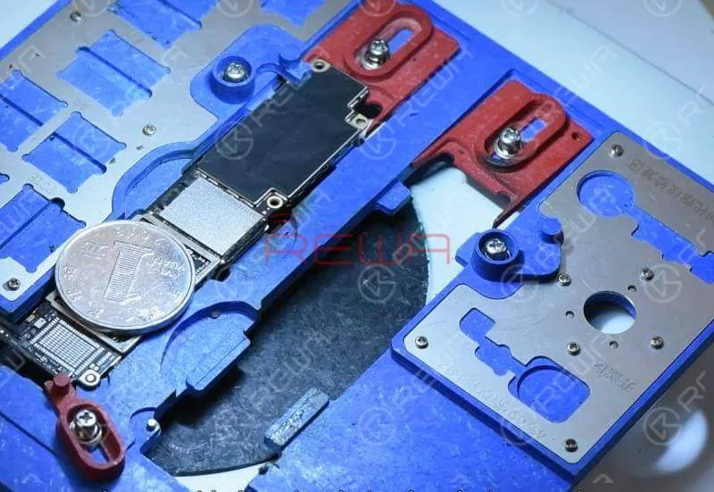
    Heat with the QUICK 990AD Hot Air Gun to remove black adhesive around the NAND flash chip.

    Since there are multiple components around the NAND flash chip, to protect these components from high-temperature damage, we need to provide heat insulation by placing a coin.
    Heat with the QUICK 990AD Hot Air Gun to remove black adhesive around the NAND flash chip. Since there are multiple components around the NAND flash chip, to protect these components from high-temperature damage, we need to provide heat insulation by placing a coin.

    Once the NAND flash chip has been removed, continue to apply some Paste Flux to the bonding pad and then some middle-temperature solder paste.

    Heat with the Soldering Iron to neutralize the melting temperature on the bonding pad.

    Continue to apply Paste Flux to the detached NAND flash chip and clean the NAND flash chip with the Soldering Iron.

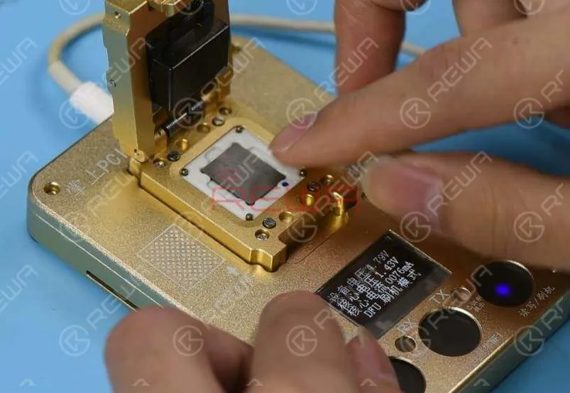
    Place the NAND flash chip into the PCIE Programmer and run the software to complete WiFi unbinding. Once done, take out the NAND flash chip.
    Continue to apply Paste Flux to the detached NAND flash chip and clean the NAND flash chip with the Soldering Iron. Place the NAND flash chip into the PCIE Programmer and run the software to complete WiFi unbinding. Once done, take out the NAND flash chip.

    NAND Reballing

    Next, we need to reball the NAND flash chip.

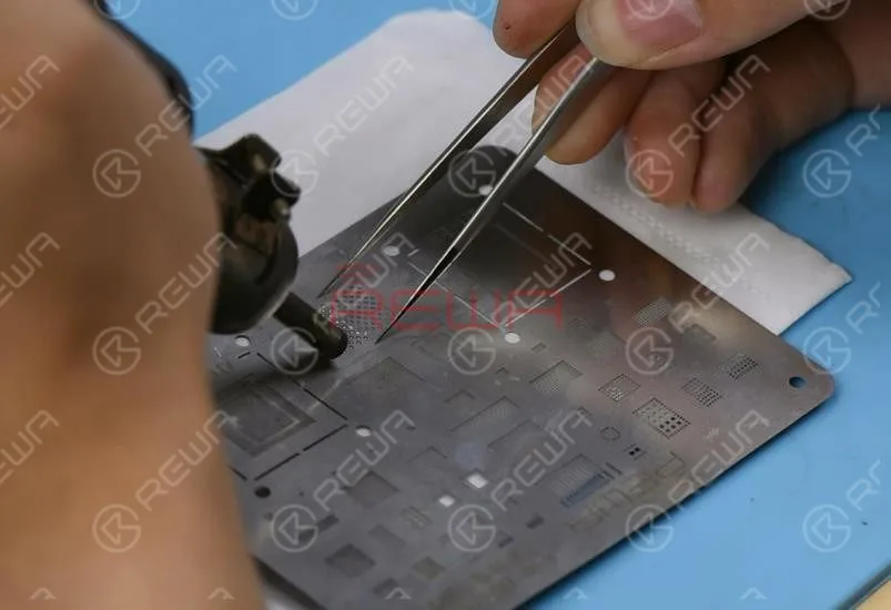
    Get the BGA Reballing Stencil well aligned with the chip.

    Smear Soldering Paste evenly on the BGA reballing stencil and then heat evenly with the QUICK 990AD Hot Air Gun so that all solder balls can solidify completely.
    Next, we need to reball the NAND flash chip. Get the BGA Reballing Stencil well aligned with the chip. Smear Soldering Paste evenly on the BGA reballing stencil and then heat evenly with the QUICK 990AD Hot Air Gun so that all solder balls can solidify completely.

    Once done, separate the chip from the BGA reballing stencil and clean the NAND flash chip with PCB Cleaner afterwards.

    Chip Soldering

    Now we can solder the NAND flash chip and a new WiFi module onto the board.

    Apply some Paste Flux to the bonding pad.

    Get the NAND flash chip in position.

    Make sure you put it in the right direction.

    Solder with the QUICK 990AD Hot Air Gun.

    Now we can solder the NAND flash chip and a new WiFi module onto the board.Apply some Paste Flux to the bonding pad. Get the NAND flash chip in position. Make sure you put it in the right direction. Solder with the QUICK 990AD Hot Air Gun.

    Continue to apply Paste Flux to the bonding pad of the WiFi module and get a new WiFi module in position. Solder with the QUICK 990AD Hot Air Gun afterwards.

    Reassemble And Test

    Now we can assemble the phone and test. Get the logic board and display assembly installed. Connect the battery and press the power button.

    The phone turns on normally.

    Now we can assemble the phone and test. Get the logic board and display assembly installed. Connect the battery and press the power button . The phone turns on normally.

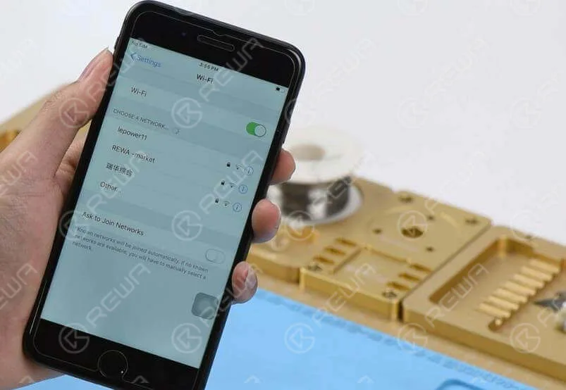
    Go to Settings>WiFi. The WiFi switch is back to normal. Networks in range can be picked normally. Fault cleared.

    Tools Used

    Hot Air Gun Rework Station – 990AD

    Integrated Repair Platform

    Digital Multimeter

    Communication Maintenance Power Supply

    Electron Microscope 

    PCIE NAND Flash Memory Chip Programmer For iPhone8/8 Plus/X

    Free Schematic Software: Refox

    Visit our online shop for more parts and tools.

    You can also visit REWA YouTube Channel to check our video and learn how to repair the iPhone 8 plus wifi not working issue step by step.