Tag: iphone 11 pro

  • iPhone 11 Pro Won’t Turn on – Professional Repair Guide

    iPhone 11 Pro Won’t Turn on – Professional Repair Guide

    Hello everyone! Our course today is about repairing an iPhone 11 Pro that won’t turn on.

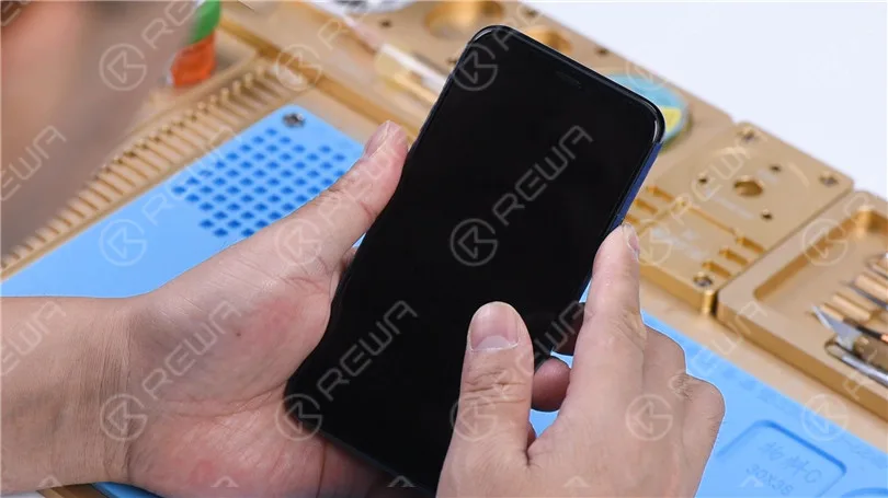
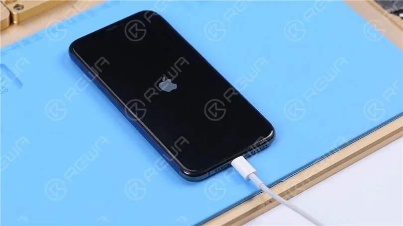
    Press the power button. The phone won’t turn on.
    How to Fix iPhone 11 Won't Turn On with Large Current

    Disassemble and Test

    Then we disassemble the phone and test.

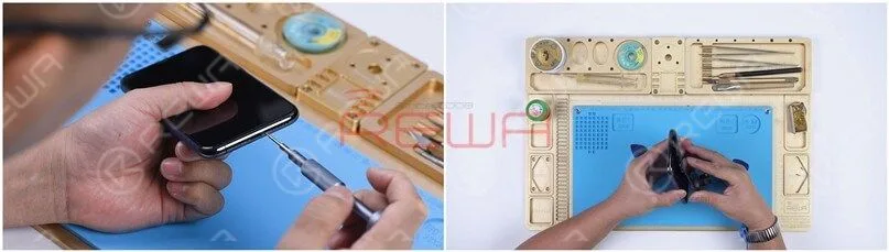
    Remove the two pentalobe screws at the bottom edge.

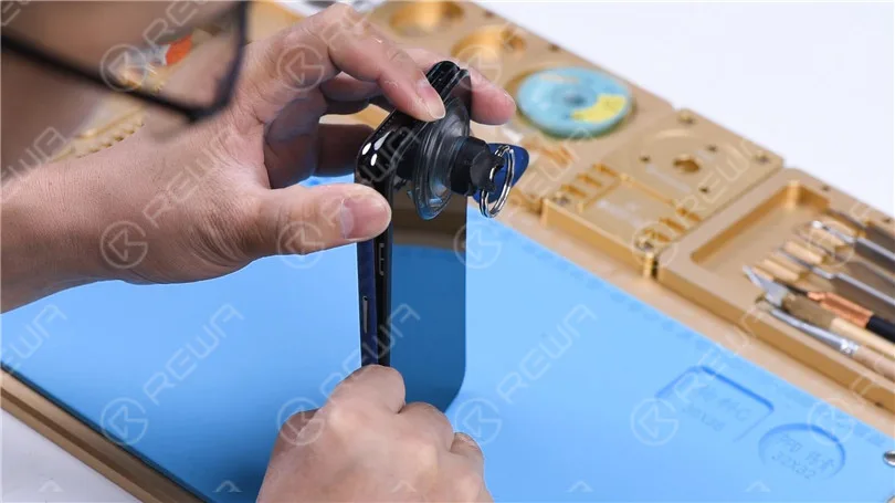
    Pull up on the small nub on the Suction Cup to lift the screen.

    Insert a Pry Piece when there is a gap and slide it along the gap.
    How to Fix iPhone 11 Won't Turn On with Large Current

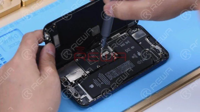
    After the screen is lifted, take the shielding covers off.

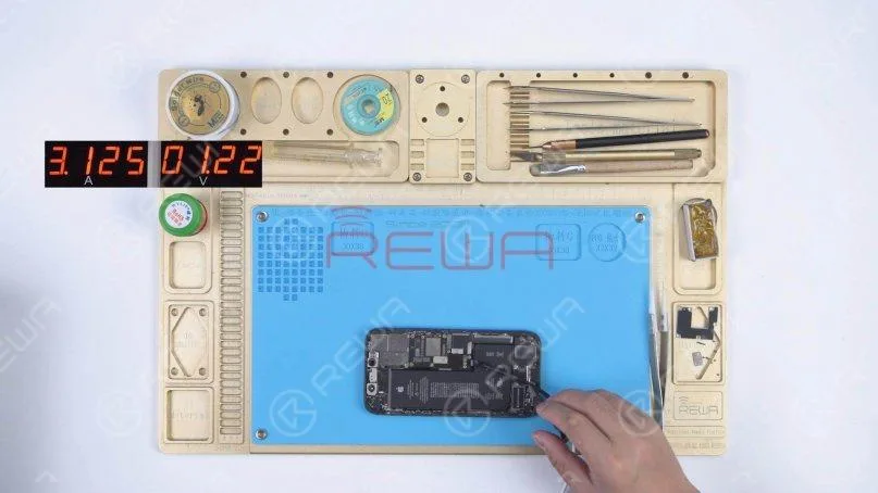
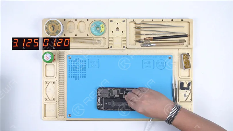
    Disconnect the battery and remove the screen. Connect the motherboard with the Power Cable.

    The ammeter shows a large current of 3.1A.
    How to Fix iPhone 11 Won't Turn On with Large Current

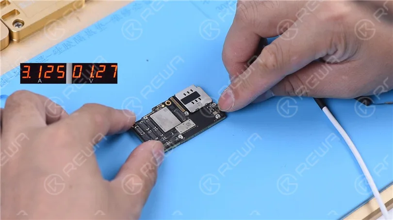
    Disconnect the flex cables. Remove the SIM card tray.

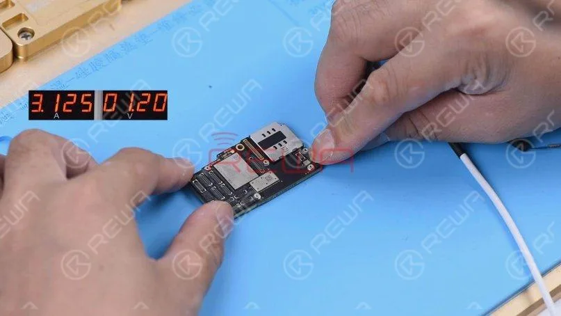
    Detach the motherboard. Connect the motherboard with the Power Cable again.

    The ammeter still shows a large current of 3.1A.

    It indicates that the large current has nothing to do with other flex cables.

    The fault is on the motherboard.
    How to Fix iPhone 11 Won't Turn On with Large Current

    Diode Mode Measurement

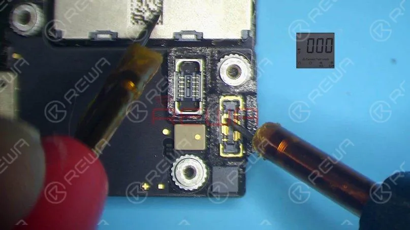
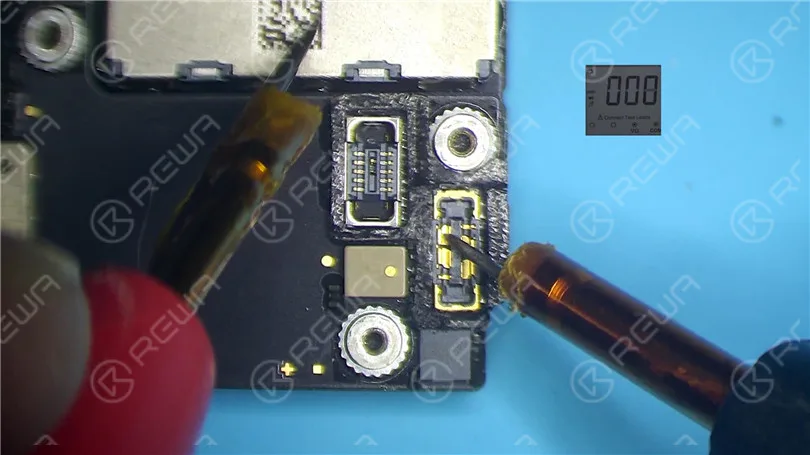
    Run diode mode measurement of pin 1 on the J7010 of the battery connector.

    The diode value is 0. It indicates that the main power supply circuit is shorted to the ground.

    Since the circuit simultaneously supplies power for the logic board and signal board, we need to separate the motherboard to locate the fault.
    How to Fix iPhone 11 Won't Turn On with Large Current

    Motherboard Separation

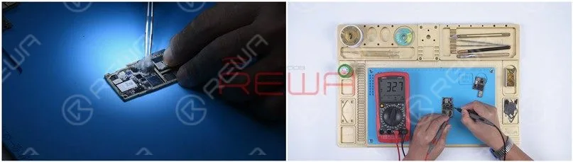
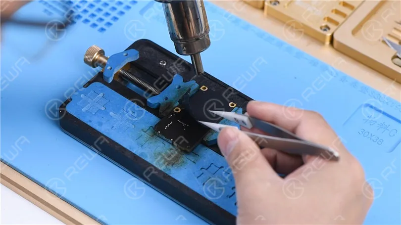
    Remove foam on the motherboard.

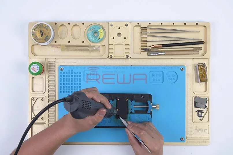
    Heat the back of the motherboard with Hot Air Gun at 240 degrees celsius.

    Remove the shielding paper.

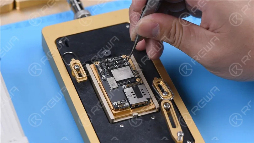
    Put the motherboard on the Heating Platform.

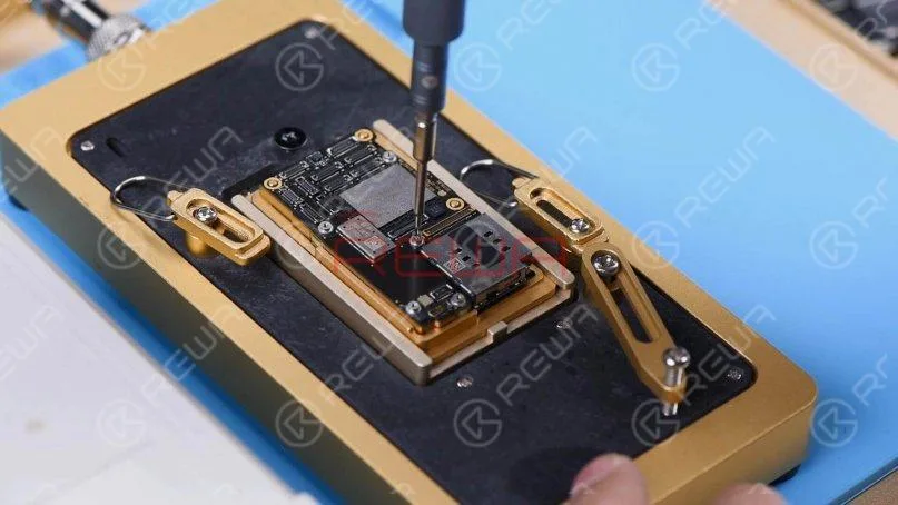
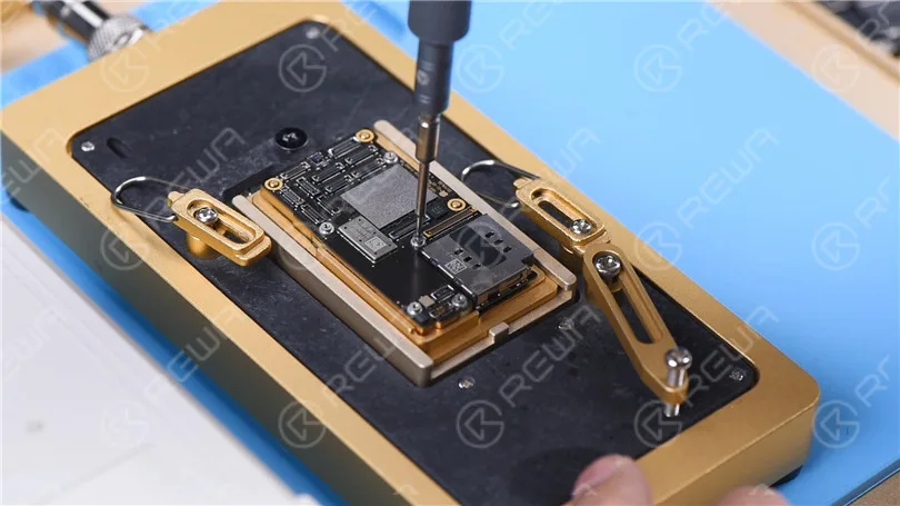
    To make it easier to remove the logic board after separation, drive a screw on the logic board.

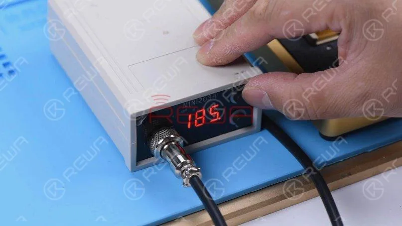
    Set the temperature of the Heating Platform to 185 degrees celsius.

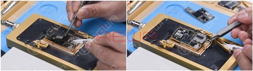
    Clamp the screw to remove the logic board when the temperature has risen to 185 degrees celsius. Remove the signal board.
    How to Fix iPhone 11 Won't Turn On with Large Current
    How to Fix iPhone 11 Won't Turn On with Large Current

    Diode Mode Measurement

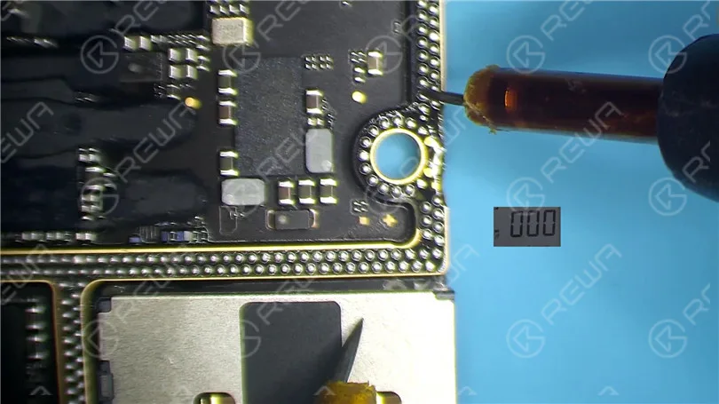
    Run diode mode measurement of pin 286 on the signal board. The diode value is 0.

    It indicates that the main power supply of the signal board is shorted to the ground.

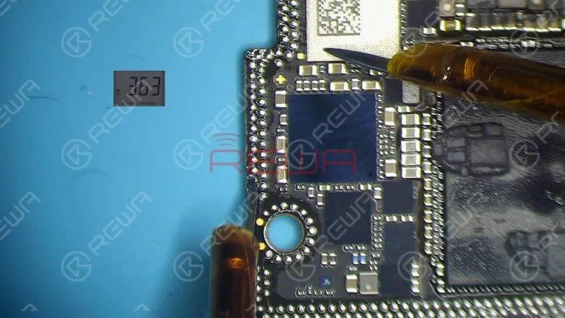
    Measure pin 286 on the logic board.

    The diode value is 363 which means the logic board is normal.
    How to Fix iPhone 11 Won't Turn On with Large Current
    How to Fix iPhone 11 Won't Turn On with Large Current

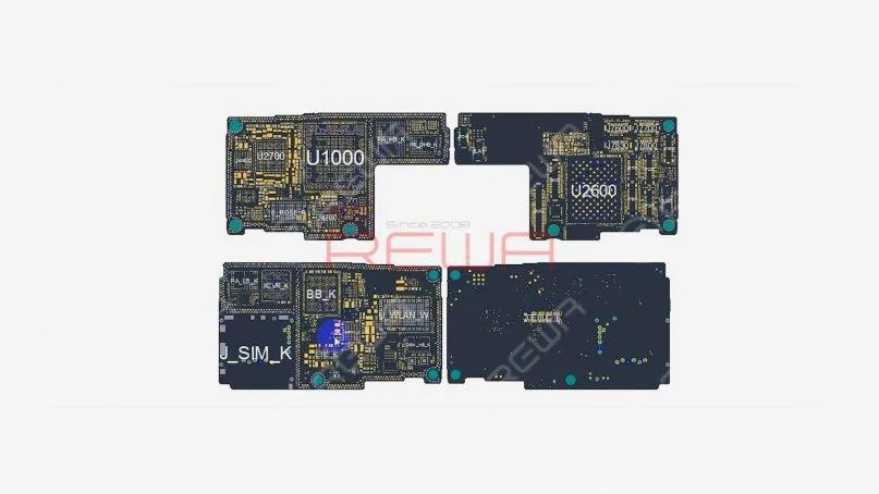
    Open the bitmap. We can see there are many associated components on the main power supply circuit.

    How to Fix iPhone 11 Won't Turn On with Large Current

    Rosin Detecting

    Next, we need to locate the faulty component with rosin detecting.

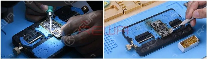
    Remove thermal grease with a Sculpture Knife.

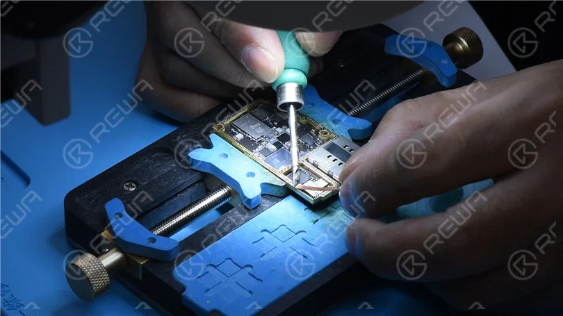
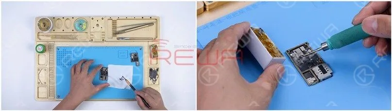
    Dip rosin with Soldering Iron at 365 degrees celsius.

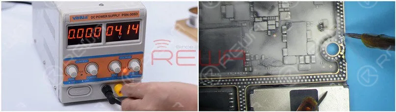
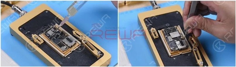
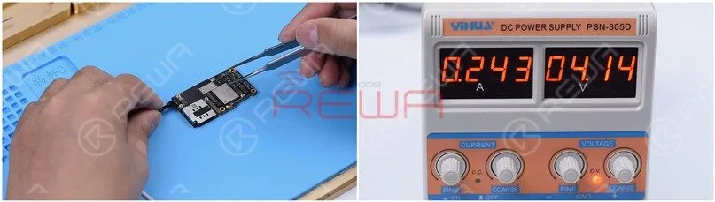
    Smoke rosin on the signal board. Set the direct current supply to 4.1V.

    Connect the positive and negative anode of the direct current supply with multimeter probes.

    Connect the black probe to the ground.

    Connect the red probe to pin 286 on the signal board.

    We can see rosin on C1200 K has melted. It indicates that the capacitor is damaged.

    How to Fix iPhone 11 Won't Turn On with Large Current
    How to Fix iPhone 11 Won't Turn On with Large Current

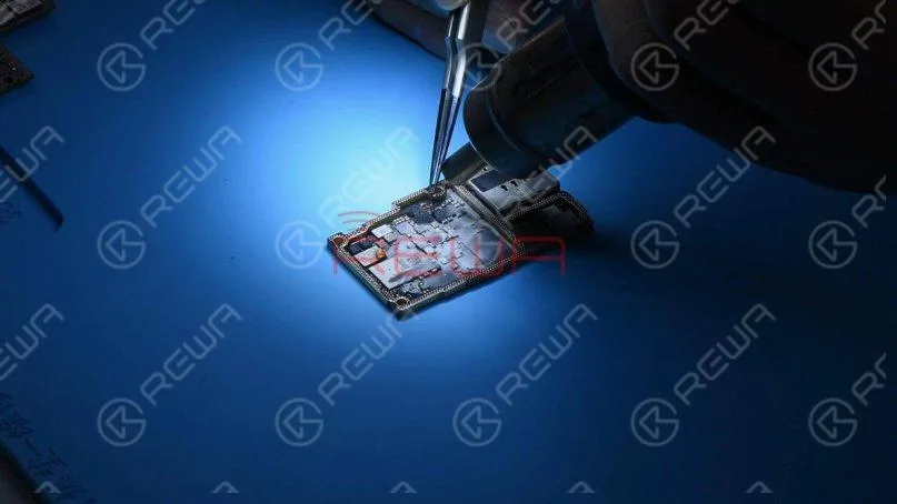
    Then we heat it with Hot Air Gun at 350 degrees celsius. Remove the capacitor with tweezers.

    How to Fix iPhone 11 Won't Turn On with Large Current

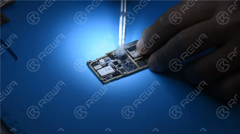
    Clean rosin on the signal board with PCB Cleaner. Run a second diode mode measurement. The diode value returns to a normal value of 327.

    How to Fix iPhone 11 Won't Turn On with Large Current
    How to Fix iPhone 11 Won't Turn On with Large Current

    Motherboard Recombination

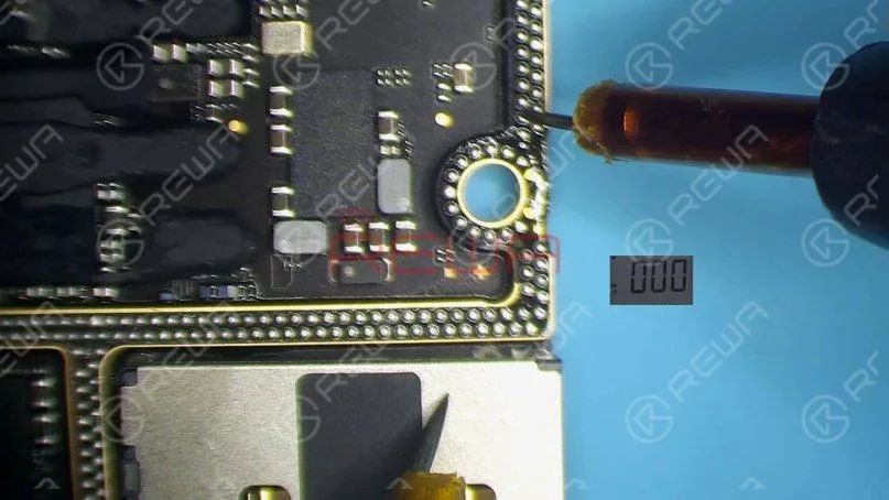
    Smear rosin with Soldering Iron and solder wick at 365 degrees celsius to remove tin on the bonding pad.

    Clean the signal board with PCB Cleaner. Remove tin and clean the logic board with the same method.

    How to Fix iPhone 11 Won't Turn On with Large Current

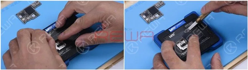
    Attach the signal board to the Reballing Platform.

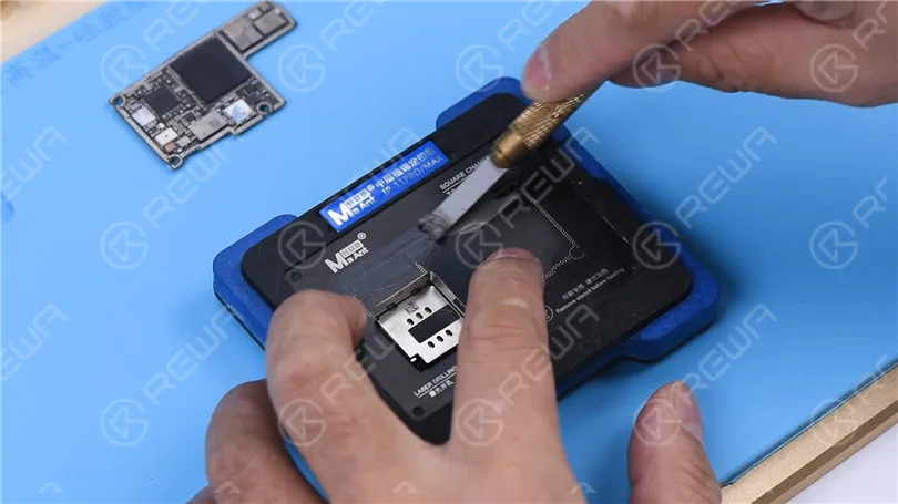
    Put the Reballing Stencil in position. To prevent the solder paste from flowing into the motherboard crevices, insert a metal plate.

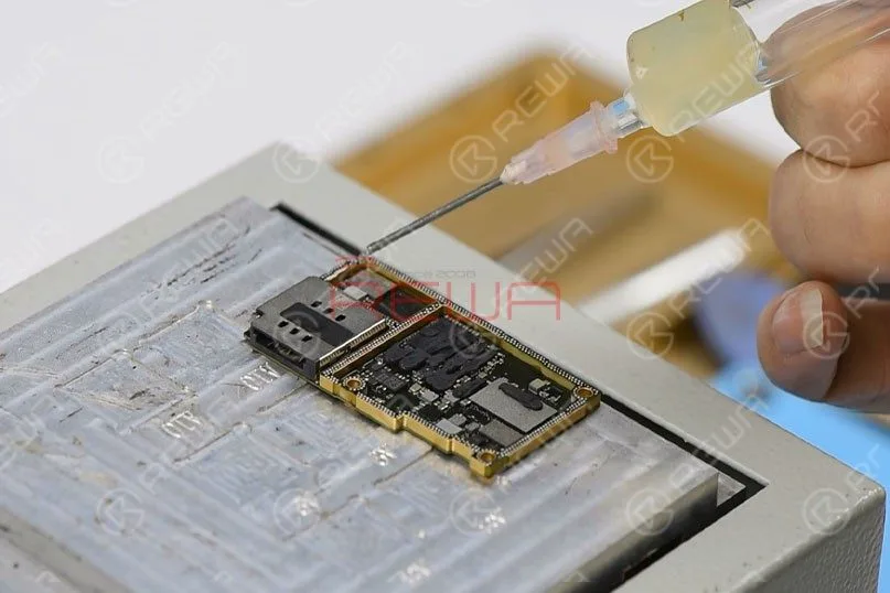
    Apply a layer of low-temperature Solder Paste.

    Remove the Reballing Stencil.

    How to Fix iPhone 11 Won't Turn On with Large Current

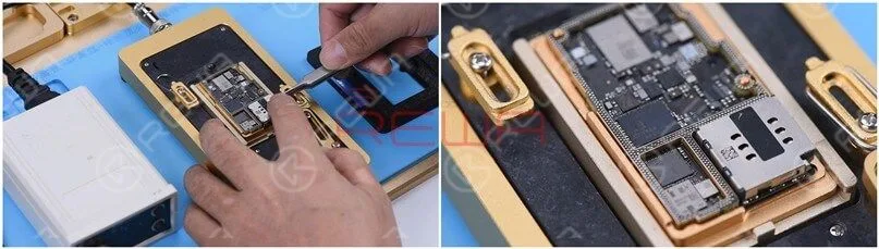
    Put the signal board on the Heating Platform at 185 degrees celsius to heat.

    After the solder balls are formed, turn the power off and cool the motherboard for 5 minutes.

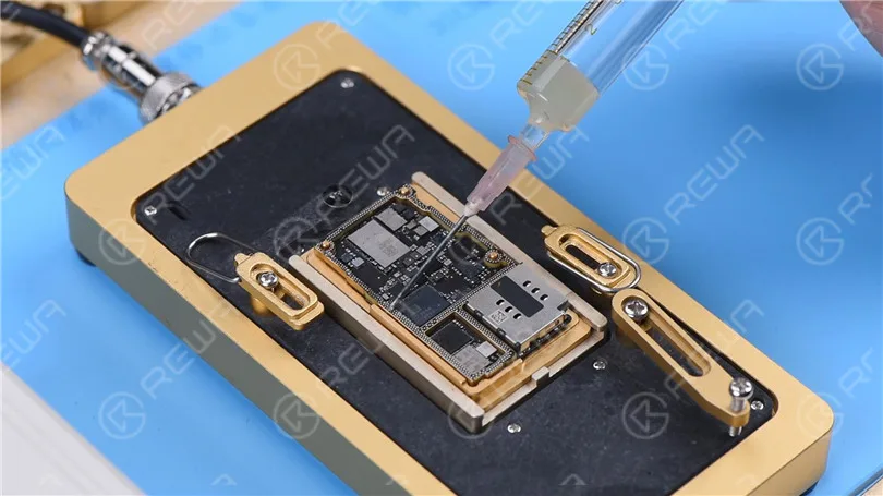
    Apply some Paste Flux.

    Align the logic board with the signal board.

    Keep heating on the Heating Platform at 185 degrees celsius.

    When the temperature reaches 185 degrees celsius, keep heating for 1 minute.

    This step is to ensure that the logic board and the signal board fit closely.

    How to Fix iPhone 11 Won't Turn On with Large Current
    How to Fix iPhone 11 Won't Turn On with Large Current
    How to Fix iPhone 11 Won't Turn On with Large Current

    Testing

    Connect the motherboard with the Power Cable.

    Short to the ground of the J7700 pin 12. The boot current becomes normal.

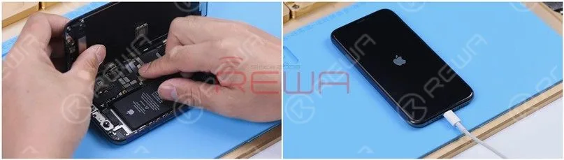
    Put the motherboard on the phone.

    Connect the flex cables. Connect the screen and battery.

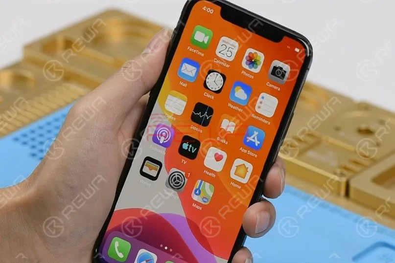
    Because the battery is dead. Plug the charging cable and the phone turns on normally.

    How to Fix iPhone 11 Won't Turn On with Large Current
    How to Fix iPhone 11 Won't Turn On with Large Current
  • How to Fix an iPhone 11 Pro Won’t Turn On

    How to Fix an iPhone 11 Pro Won’t Turn On

    Having trouble with your iPhone 11 Pro refusing to turn on? Don’t worry, we’ve got your back! In this comprehensive guide, we’ll walk you through some practical and effective solutions to fix this frustrating issue.

    Step 1: Disassemble and test

    Remove the two pentalobe screws at the bottom edge and lift the screen.
    Remove the two pentalobe screws at the bottom edge and lift the screen.

    After the screen is lifted, take the shielding covers off, disconnect the battery, and remove the screen.
    After the screen is lifted, take the shielding covers off, disconnect the battery, and remove the screen.

    Connect the motherboard with the Power Cable. The ammeter shows a large current of 3.1A.
    Connect the motherboard with the Power Cable. The ammeter shows a large current of 3.1A.

    Detach the motherboard and connect the motherboard with the Power Cable again. The ammeter still shows a large current of 3.1A.
    Detach the motherboard and connect the motherboard with the Power Cable again. The ammeter still shows a large current of 3.1A.

    It indicates that the large current has nothing to do with other flex cables. The fault is on the motherboard.

    Step 2: Run diode mode measurement

    Run diode mode measurement of pin 1 on the J7010 of the battery connector. The diode value is 0 which indicates that the main power supply circuit is shorted to the ground.

    Run diode mode measurement of pin 1 on the J7010 of the battery connector. The diode value is 0 which indicates that the main power supply circuit is shorted to the ground.

    Since the circuit simultaneously supplies power for the logic board and signal board, we need to separate the motherboard to locate the fault.

    Step 3: Motherboard separation

    Remove foam on the motherboard. Then heat the back of the motherboard with Hot Air Gun at 240℃ to remove the shielding paper.
    Remove foam on the motherboard. Then heat the back of the motherboard with Hot Air Gun at 240℃ to remove the shielding paper.

    Put the motherboard on the Heating Platform. To make it easier to remove the logic board after separation, drive a screw on the logic board.
    Put the motherboard on the Heating Platform. To make it easier to remove the logic board after separation, drive a screw on the logic board.

    Set the temperature of the Heating Platform to 185℃.

    Set the temperature of the Heating Platform to 185℃.

    Clamp the screw to remove the logic board when the temperature has risen to 185℃. Lastly, remove the signal board.
    Clamp the screw to remove the logic board when the temperature has risen to 185℃. Lastly, remove the signal board.

    Step 4: Run diode mode measurement again

    Run diode mode measurement of pin 286 on the signal board. The diode value is 0. It suggests that the main power supply of the signal board is shorted to the ground.

    Run diode mode measurement of pin 286 on the signal board. The diode value is 0. It suggests that the main power supply of the signal board is shorted to the ground.

    Measure pin 286 on the logic board. The diode value is 363 which means the logic board is normal.
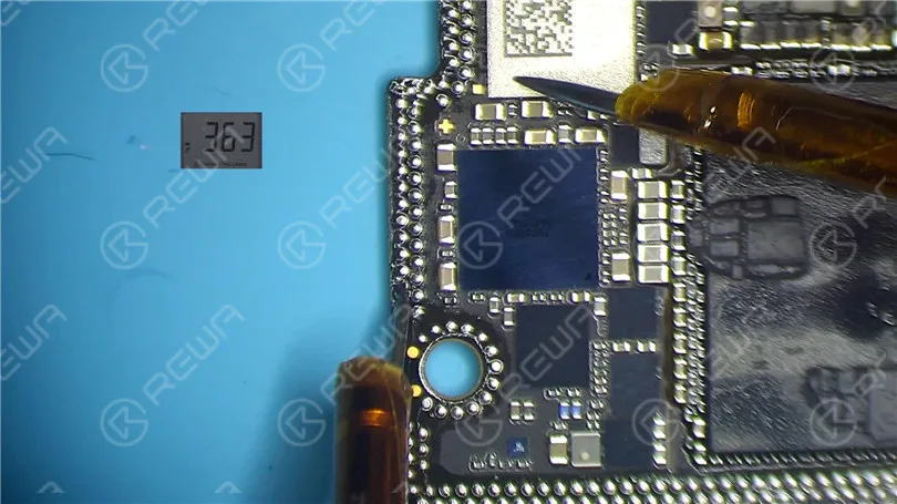
    Measure pin 286 on the logic board. The diode value is 363 which means the logic board is normal.

    Open the bitmap. We can see there are many associated components on the main power supply circuit.
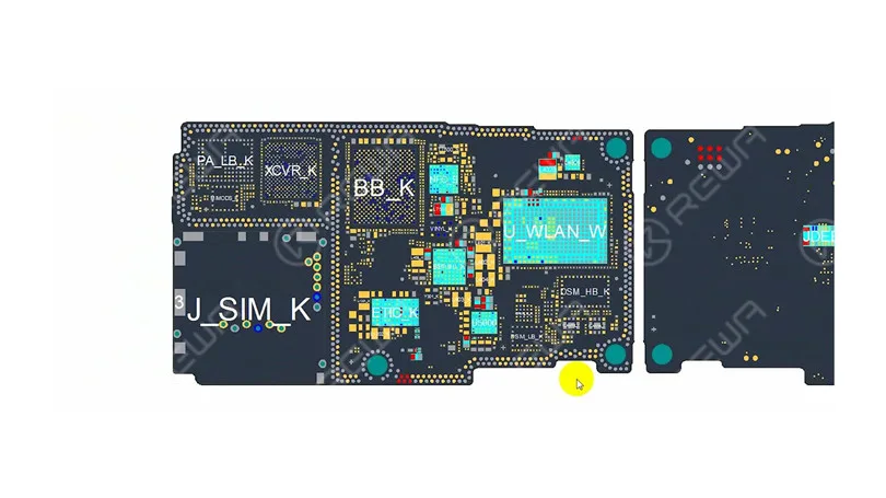
    Open the bitmap. We can see there are many associated components on the main power supply circuit.

    Step 5: Rosin detecting to locate the fault

    Next, we need to locate the faulty component with rosin detecting.Remove thermal grease with a Sculpture Knife. Then dip rosin with Soldering Iron at 365℃ and smoke rosin on the signal board.

    Next, we need to locate the faulty component with rosin detecting.Remove thermal grease with a Sculpture Knife. Then dip rosin with Soldering Iron at 365℃ and smoke rosin on the signal board.

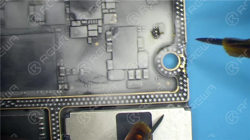
    Set the direct current supply to 4.1V. Connect the positive and negative anode of the direct current supply with multimeter probes. Connect the black probe to the ground and connect the red probe to pin 286 on the signal board. We can see rosin on C1200_K has melted. It indicates that the capacitor is damaged.
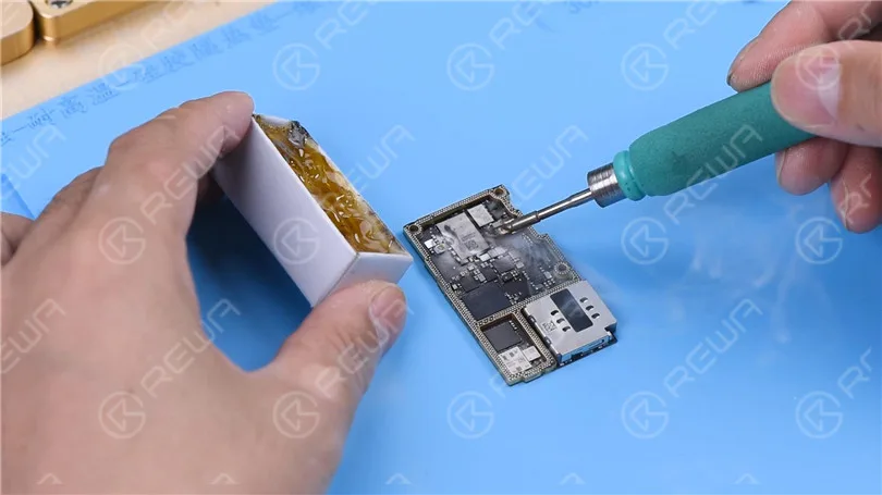
    Set the direct current supply to 4.1V. Connect the positive and negative anode of the direct current supply with multimeter probes. Connect the black probe to the ground and connect the red probe to pin 286 on the signal board. We can see rosin on C1200_K has melted. It indicates that the capacitor is damaged.
    Step 6: Eliminate the fault and restore the motherboard

    Then we heat the damaged capacitor with Hot Air Gun at 350℃ and remove it with tweezers.

    Then we heat the damaged capacitor with Hot Air Gun at 350℃ and remove it with tweezers.

    Clean rosin on the signal board with PCB Cleaner. Run a second diode mode measurement. The diode value returns to a normal value of 327.
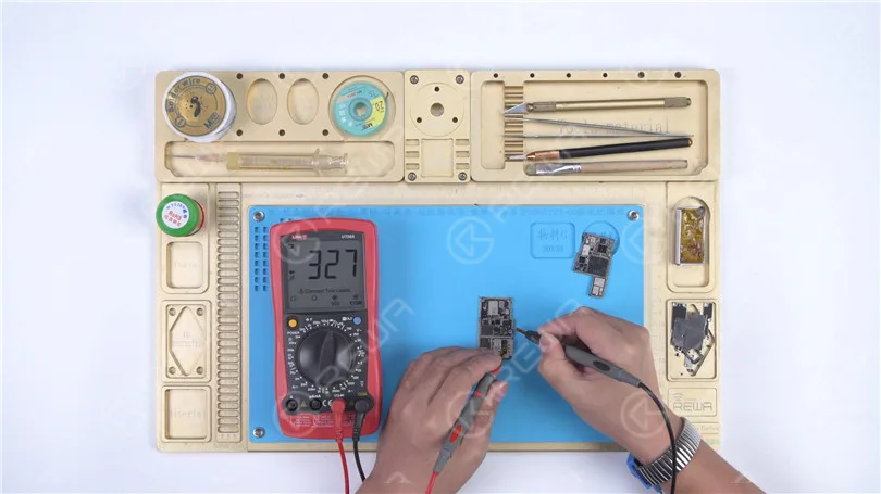
    Clean rosin on the signal board with PCB Cleaner. Run a second diode mode measurement. The diode value returns to a normal value of 327.

    Smear rosin with Soldering Iron and solder wick at 365℃ to remove tin on the bonding pad. Clean the signal board with PCB Cleaner.

    Smear rosin with Soldering Iron and solder wick at 365℃ to remove tin on the bonding pad. Clean the signal board with PCB Cleaner.

    Remove tin and clean the logic board with the same method.Attach the signal board to the Reballing Platform and put the Reballing Stencil in position. To prevent the solder paste from flowing into the motherboard crevices, insert a metal plate. Apply a layer of low-temperature Solder Paste. 

    Remove tin and clean the logic board with the same method.Attach the signal board to the Reballing Platform and put the Reballing Stencil in position. To prevent the solder paste from flowing into the motherboard crevices, insert a metal plate. Apply a layer of low-temperature Solder Paste.

    Remove the Reballing Stencil and put the signal board on the Heating Platform at 185℃ to heat. After the solder balls are formed, turn the power off and cool the motherboard for 5 minutes.

    Remove the Reballing Stencil and put the signal board on the Heating Platform at 185℃ to heat. After the solder balls are formed, turn the power off and cool the motherboard for 5 minutes.

    Apply some Paste Flux and align the logic board with the signal board. Keep heating on the Heating Platform at 185℃. When the temperature reaches 185℃, keep heating for 1 minute.This step is to ensure that the logic board and the signal board fit closely.
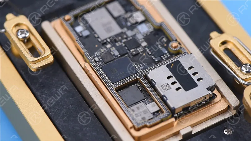
    Apply some Paste Flux and align the logic board with the signal board. Keep heating on the Heating Platform at 185℃. When the temperature reaches 185℃, keep heating for 1 minute.This step is to ensure that the logic board and the signal board fit closely.Step 7: Test and assemble

    Connect the motherboard with the Power Cable and short to the ground of the J7700 pin 12. The boot current becomes normal.

    Connect the motherboard with the Power Cable and short to the ground of the J7700 pin 12. The boot current becomes normal.

    Put the motherboard on the phone. Connect the flex cables, screen, and battery. Because the battery is dead, plug the charging cable and the phone turns on normally.
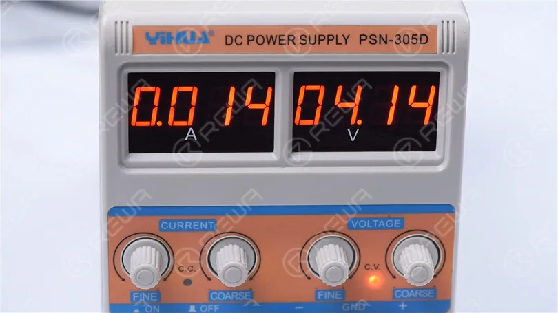
    Put the motherboard on the phone. Connect the flex cables, screen, and battery. Because the battery is dead, plug the charging cable and the phone turns on normally.
    Conclusion

    iPhone 11 Pro won’t turn on with a large current. We found that the main power supply was shorted to the ground through measuring the battery connector. The fault was found to be on the signal board after separation. Rosin detecting showed us that C1200_K was damaged. After removing C1200_K, the fault was cleared.

  • iPhone 11 Pro Motherboard Separation

    iPhone 11 Pro Motherboard Separation

    As we all know, iPhone new series have undergone considerable changes on both inside and outside.

    Especially on the motherboard.

    How will these changes affect the repair industry?

    Will it make third-party repair harder or easier?

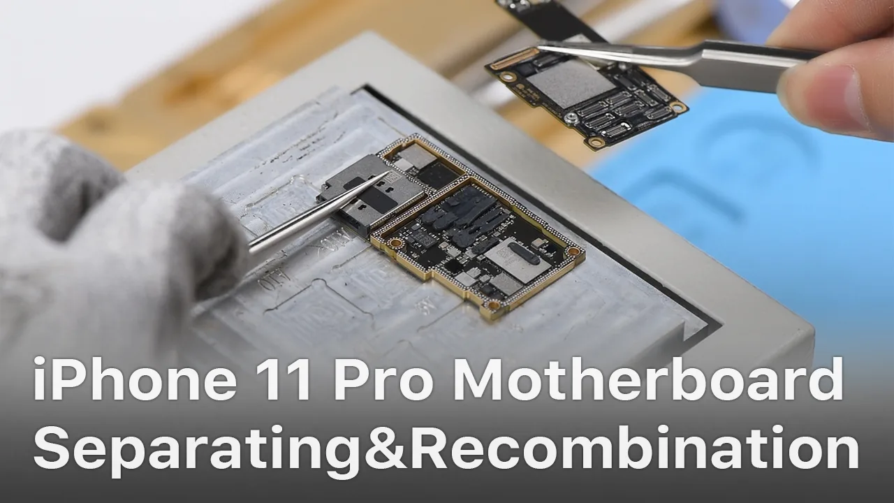
    Follow our iPhone 11 Pro motherboard separation & recombination blog today and find the answer by yourself.

    iPhone 11 Pro Motherboard Separation

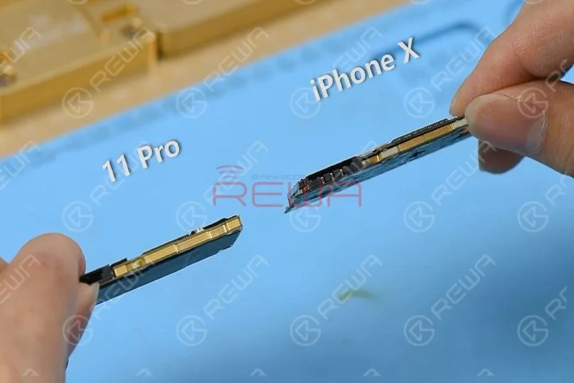
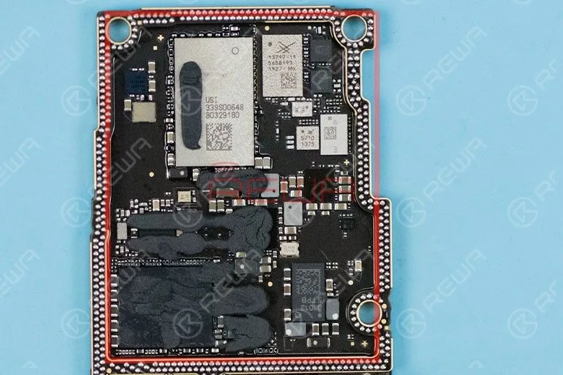
    Compared with iPhone X series, iPhone 11 Pro’s motherboard is smaller with a much denser component array.

    It is also thicker.

    There are layers of graphite thermal transfer material on the backside.

    It can dissipate heat generated from the motherboard efficiently.
    Compared with iPhone X series, iPhone 11 Pro’s motherboard is smaller with a much denser component array. It is also thicker. There are layers of graphite thermal transfer material on the backside. It can dissipate heat generated from the motherboard efficiently.

    Step 1

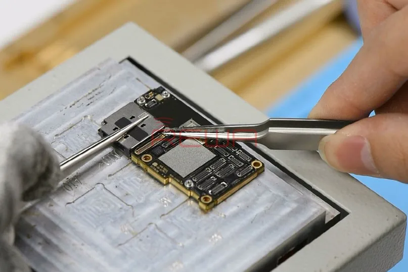
    Remove the graphite thermal transfer material with tweezers first.

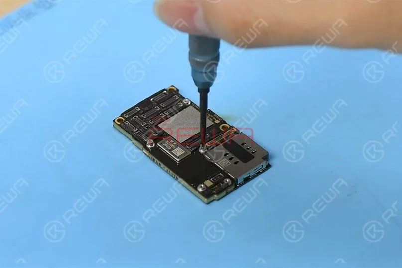
    To recombine the two layers without reballing after separation, let’s fit two screws into the screw holes reserved on the motherboard.

    Remove the graphite thermal transfer material with tweezers first. To recombine the two layers without reballing after separation, let’s fit two screws into the screw holes reserved on the motherboard.

    Step 2

    Set temperature of the heating platform at 170℃.

    With temperature of the platform reaching 170℃, place the motherboard on the platform to heat for 3 minutes.

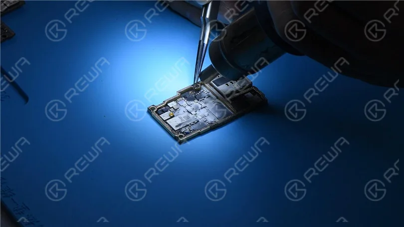
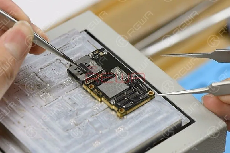
    Press the SIM card reader with the tweezers and push the upper layer with another tweezers slightly.
    Set temperature of the heating platform at 170℃. With temperature of the platform reaching 170℃, place the motherboard on the platform to heat for 3 minutes. Press the SIM card reader with the tweezers and push the upper layer with another tweezers slightly.

    Step 3

    With solder balls on the third space PCB starting to melt, clamp the screws fitted into the screw holes with tweezers and pick up the upper layer with tweezers vertically.

    Tips: do not shake the tweezers when picking up the upper layer.

    The third space PCB might be stuck in bridging issues and the recombination work would also be affected.

    Continue to pick up the lower layer.

    iPhone 11 Pro Motherboard Structure

    Now let’s start with the structure of the motherboard.

    The Upper Layer

    iPhone 11 Pro Motherboard Structure

    A.Thermal Compound

    CPU and areas around CPU are covered with a large amount of thermal compound to dissipate heat generated from A13 CPU.

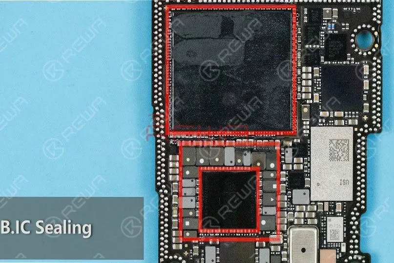
    B.IC Sealing

    CPU, PMU, and inductors around PMU are sealed with adhesive adding to the difficulty of repairs to some extent.

    C.Dense Component Array Around PMU

    Professional handwork is required when soldering/desoldering PMU.

    D.USB IC

    Unlike iPhone X series, the USB IC of iPhone 11 Pro hasn’t been sealed with adhesive, and it is far from CPU.

    Therefore, the difficulty of USB IC relevant repairs is relatively reduced

    Unlike iPhone X series, the A13 CPU of iPhone 11 Pro is not located right on the backside of the NAND flash chip.

    This can reduce the bridging possibility of CPU when soldering/desoldering the NAND flash chip.

    The Lower Layer

    The Lower Layer

    A. Different from iPhone X series, the lower layer of iPhone 11 Pro has a dispersive component array. Therefore, the difficulty of signal relevant repairs is also reduced.

    B. Unlike iPhone X series, the SIM card reader of iPhone 11 Pro is independent from other components. We don’t have to remove the SIM card reader when working on signal relevant repairs.

    iPhone 11 Pro Motherboard Recombination Without Reballing

    Set temperature of the heating platform at 170℃.

    With temperature of the platform reaching 170℃, place the lower layer on the platform to heat for 10 seconds.

    Apply some Paste Flux to the third space PCB evenly.

    Get the upper layer in position and heat for about 5 minutes.
    Set temperature of the heating platform at 170℃. With temperature of the platform reaching 170℃, place the lower layer on the platform to heat for 10 seconds. Apply some Paste Flux to the third space PCB evenly. Get the upper layer in position and heat for about 5 minutes.

    Then, press the SIM card reader with the tweezers and push the upper layer with another tweezers slightly.

    If the upper layer returns to the previous position automatically, then the soldering process is completed.

    Test

    Now we can assemble the phone and test.

    Test    Now we can assemble the phone and test.

    Get the motherboard and display assembly installed and get the battery connected.

    Press the power button to turn on the phone.

    The phone turns on normally.
    Run function test. All going well.

    Summary

    The separation&recombination of the motherboard of iPhone 11 Pro shows that the motherboard is smaller and more squared.

    Compared with the iPhone X series, it will not be easily damaged by external forces.

    The high integration of the motherboard also means that more professional handwork is required.

    Overall, the difficulty of iPhone 11 Pro motherboard repairs is reduced.

    Tools & Parts

    You can also visit REWA Youtube Channel to check our video of iPhone 11 Pro Motherboard Separation And Recombination.

  • iPhone 11 Pro Back Glass Repair

    iPhone 11 Pro Back Glass Repair

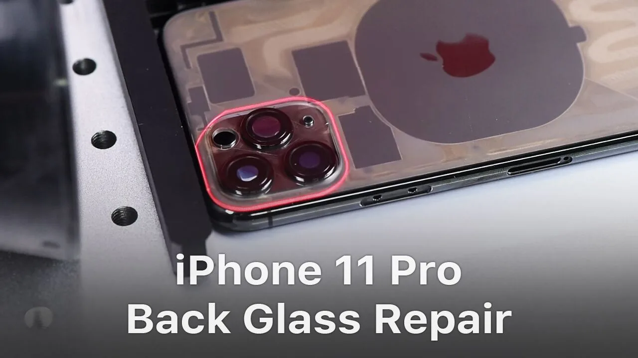
    As the most powerful and most advanced iPhone that Apple has ever built, iPhone 11 Pro  is made of a surgical grade stainless steel its back is a single piece of machine glass with an optical PVD coating, adding to the difficulty of repair.

    What’s more, the arrangement of rear cameras of iPhone 11 Pro also greatly increases the difficulty of back glass repair.

    REWA LAB tried different solutions (heating with the Hot Air Gun, separating with the dispergator/freeze assistance) and we were unable to remove the glass around the triple-lens camera safely and efficiently.

    Check our detailed operation on iPhone 11 Pro back glass repair and hope we can enlighten you somehow.

    Scan The 11 Pro Back Glass With Laser

    First of all, place the iPhone 11 Pro back glass under the probe for focusing.

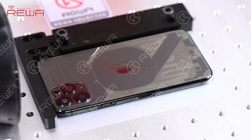
    Then place the iPhone 11 Pro back glass on the operating panel.

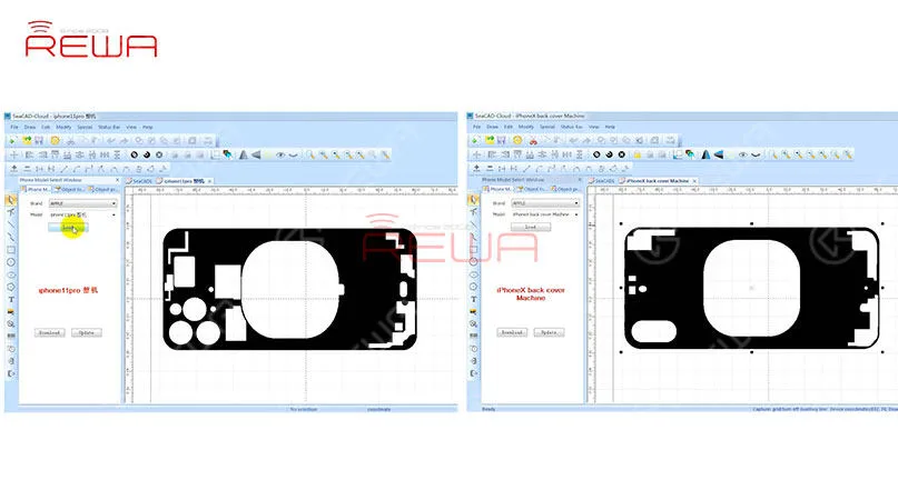
    Choose ‘iPhone 11 Pro’ from the model list and click ‘Load’ to load the drawing.

    The black area on the drawing is the area to be scanned, And the white area is the area to be retained.

    Tips: Compare the two drawings and we can see that different from iPhone X, there are more areas the laser should keep away from when scanning iPhone 11 Pro.
    First of all, place the iPhone 11 Pro back glass under the probe for focusing. Then place the iPhone 11 Pro back glass on the operating panel.   Choose ‘iPhone 11 Pro’ from the model list and click ‘Load’ to load the drawing.   The black area on the drawing is the area to be scanned, And the white area is the area to be retained.   Tips: Compare the two drawings and we can see that different from iPhone X, there are more areas the laser should keep away from when scanning iPhone 11 Pro.

    After loading the drawing of iPhone 11 Pro, adjust the laser light scanning area on the back glass.

    Once finished, get the parameter set and click ‘Mark’ to scan the back glass with the laser light.

    The back glass becomes transparent after laser scanning.
    After loading the drawing of iPhone 11 Pro, adjust the laser light scanning area on the back glass. Once finished, get the parameter set and click ‘Mark’ to scan the back glass with the laser light. The back glass becomes transparent after laser scanning.

    Scan The Glass Around The Triple-lens Camera With Laser

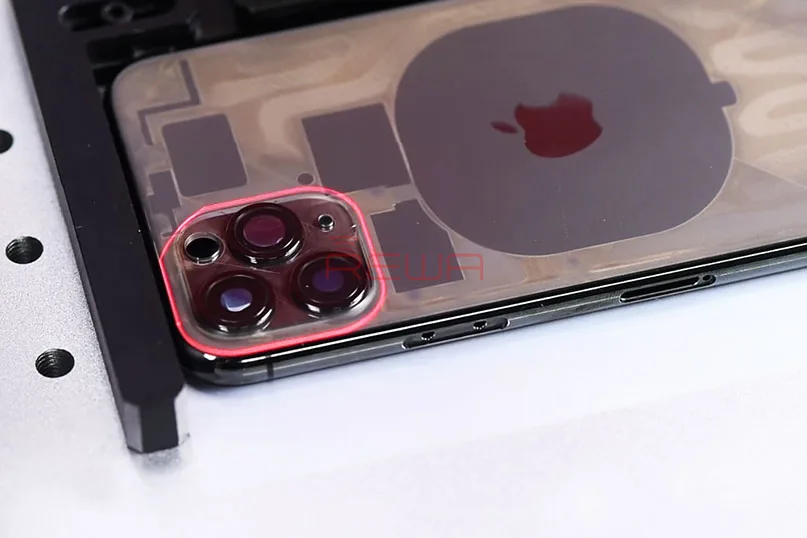
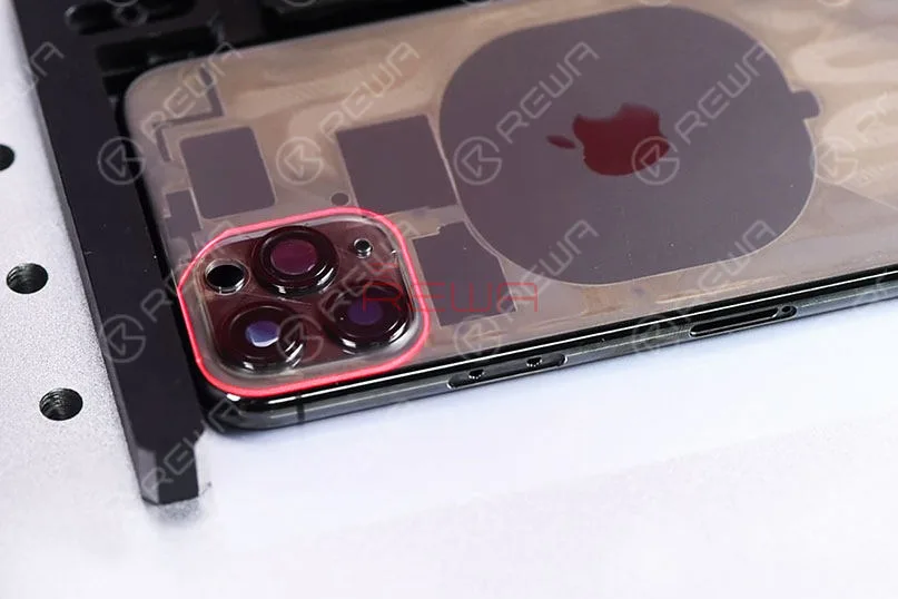
    As you can see, the glass around the triple-lens camera is relatively thick.

    The laser light scanning didn’t work well with the area here.

    After several attempts and experiments, REWA LAB successfully completed a specialized drawing for the triple-lens camera area.

    Scan the triple-lens camera area again with the laser with the help of the drawing.

    The glass around the triple-lens camera also becomes transparent after the second laser scanning.
    Scan the triple-lens camera area again with the laser with the help of the drawing. The glass around the triple-lens camera also becomes transparent after the second laser scanning.

    Separate The Back Glass From The Mid-frame 

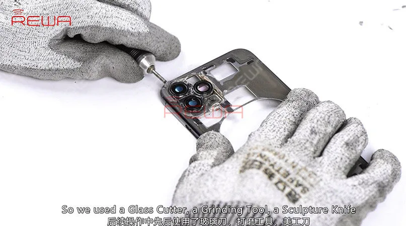
    Now we need to separate the back glass from the mid-frame. The scanned back glass can be separated easily. However, the glass around the triple-lens camera needs further operation. Our commonly used tools failed to remove the glass here, so we used a glass cutter, a grinding tool, a Sculpture Knife and a Cutting Nipper to remove the glass around the triple-lens camera. At the last, once completed, remove residual black adhesive with the Laser Machine.
    Now we need to separate the back glass from the mid-frame. The scanned back glass can be separated easily. However, the glass around the triple-lens camera needs further operation. Our commonly used tools failed to remove the glass here, so we used a glass cutter, a grinding tool, a Sculpture Knife and a Cutting Nipper to remove the glass around the triple-lens camera. At the last, once completed, remove residual black adhesive with the Laser Machine.

    The camera holder ring of iPhone 11 series is harder and comes with thick inside walls, adding to the difficulty of polishing.

    Meanwhile, the camera lens can also be easily damaged during polishing.

    So we highly recommend replacement back glass with a big camera hole for iPhone 11 series back glass repair.
    The camera holder ring of iPhone 11 series is harder and comes with thick inside walls, adding to the difficulty of polishing. Meanwhile, the camera lens can also be easily damaged during polishing. So we highly recommend replacement back glass with a big camera hole for iPhone 11 series back glass repair.

    Due to the special arrangement of the three cameras of iPhone 11 Pro, the space between the three cameras is also narrow, adding to the difficulty of back glass separating.

    Therefore, the Laser Machine may be the safest and most efficient solution for iPhone 11 Pro back glass repair.

    For more details about the back glass repair of iPhone 11 Pro, please check the video below. You can also visit REWA YouTube Channel for more videos about iPhone 11 series.

    REWA LAB will work hard to provide a better solution for iPhone 11 Pro back glass repair.

    The replacement parts of iPhone 11 series are also coming soon, please stay tuned to REWA Online Shop.

  • iPhone 11 Pro Back Glass Repair

    iPhone 11 Pro Back Glass Repair

    Rear cameras of iPhone 11 series greatly increase the difficulty of back glass repair. REWA LAB tried different solutions (heating with the Hot Air Gun, separating with the dispergator/freeze assistance) and we were unable to remove the glass around the triple-lens camera safely and efficiently. Check our iPhone 11 Pro back glass repair video now and hope we can enlighten you somehow. Please let us know your thoughts on this topic in the comment below.

    Tools & Parts used in this iPhone 11 Pro Back Glass Refurbishing video:


  • Turn iPhone 11 Pro Into iPhone 11 Pro Max

    Turn iPhone 11 Pro Into iPhone 11 Pro Max

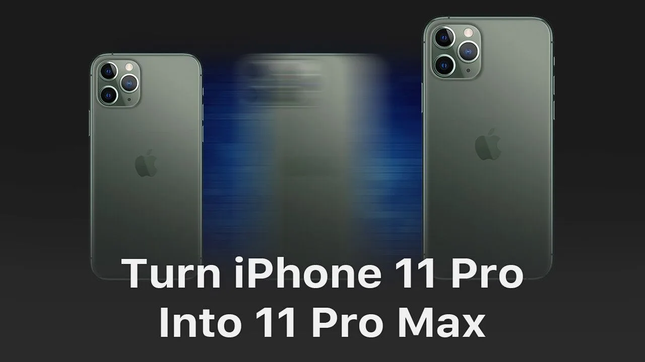
    Can iPhone 11 Pro possibly be turned into iPhone 11 Pro Max? It is actually theoretically possible. With pins of the two phones’ display connector and touch connector functioning almost the same, we can turn an iPhone 11 Pro into an iPhone 11 Pro Max by changing board ID resistors. Check our video now and find out how we finally made it.

    Warm Tips: This video is made for technique sharing only. For those who have no professional skills, please look before you leap.

    Tools & Parts used to separate iPhone 11 Pro:

  • iPhone 11 Pro Motherboard Separating & Recombination

    iPhone 11 Pro Motherboard Separating & Recombination

    iPhone new series have undergone considerable changes on both inside and outside. Especially on the motherboard. How will these changes affect the repair industry? Will it make third-party repair harder or easier? Follow our iPhone 11 Pro motherboard separation&recombination video today and find the answer by yourself.

    Tools & Parts used to separate iPhone 11 Pro: