Tag: iphone 11 pro max

  • iPhone 11 Pro Max Black Screen and No Boot Issue Repair

    iPhone 11 Pro Max Black Screen and No Boot Issue Repair

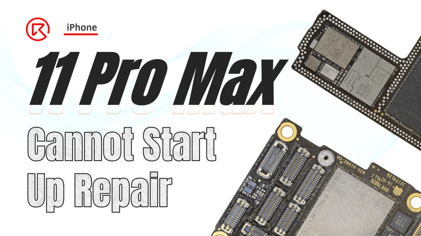
    The iPhone 11 Pro Max is a powerful device, but even the best smartphones can run into issues. One common problem is when the screen suddenly turns black, and the phone refuses to boot. In this guide, we’ll take you through the step-by-step process of diagnosing and repairing this issue. Whether you’re a professional technician or a DIY repair enthusiast, this article will help you troubleshoot and resolve the no-boot problem on your iPhone 11 Pro Max.
    iphone 11 pro max

    Phone Details

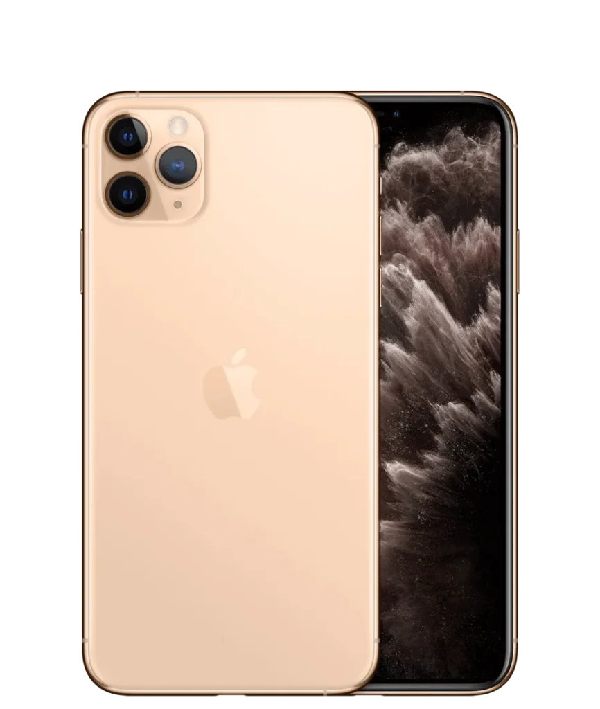
    Model: iPhone 11 Pro Max

    Announced: 2019, September 10

    Defect Phenomenon

    The iPhone 11 Pro Max suddenly experienced a black screen and could not boot during regular use.

    Troubleshooting

    1: Initial Assessment
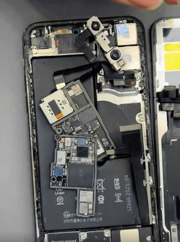
    iphone 11 pro max black screen no boot issue repair cannot start up
    • The phone was previously repaired by another technician. Upon receiving it, the motherboard was already separated. A visual inspection revealed no signs of physical damage or water exposure.

    2: Testing the Motherboard
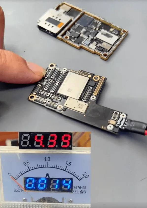
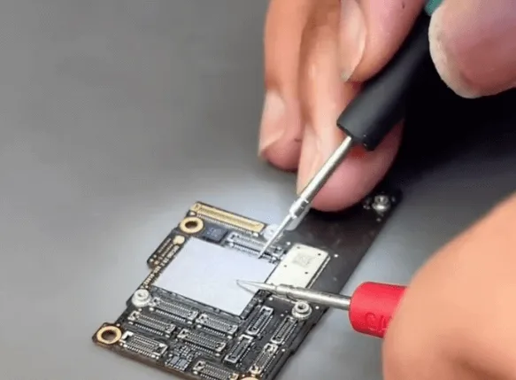
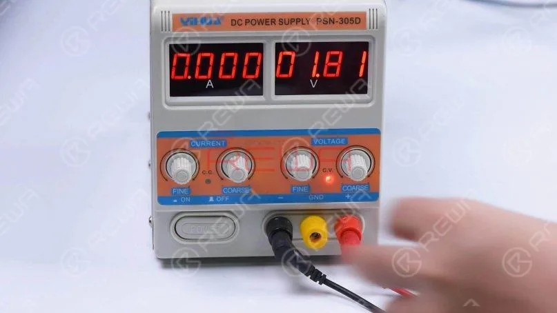
    • Connect the upper layer of the motherboard to a DC power supply and attempt to trigger the boot process using tweezers.
    • The boot current is fixed at 14mA, which suggests a problem with the NAND chip or CPU, particularly with the power supply rails.

    3: Diagnosing the Power Supply Issue
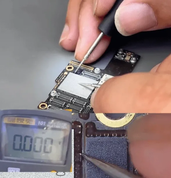
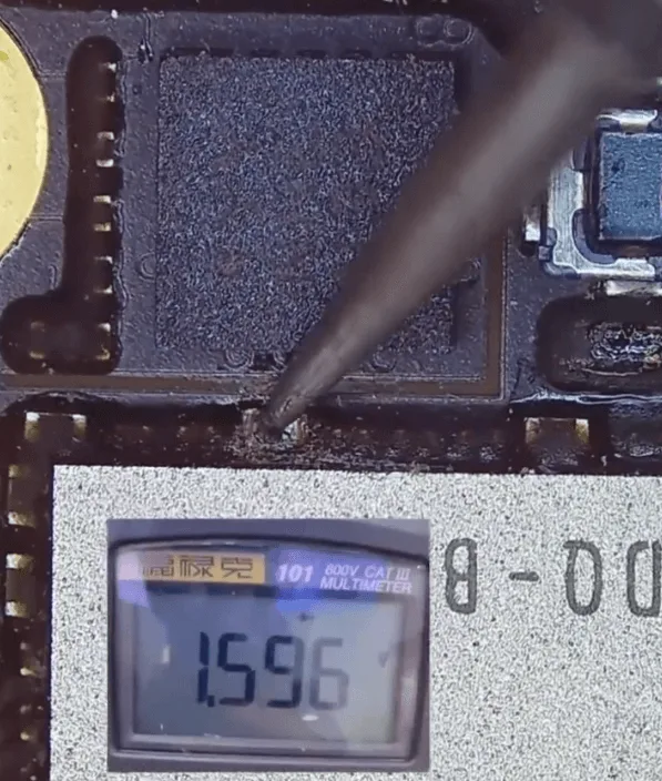
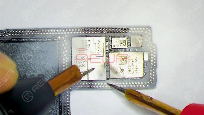
    • Use a multimeter to check the power supply rails associated with the NAND chip and CPU.
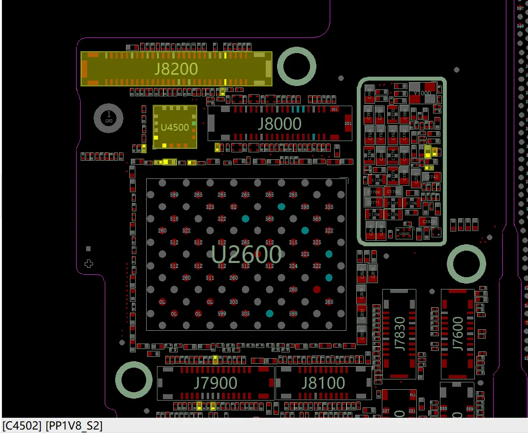
    • After carefully checking the small capacitors around the NAND chip, one rail shows a short circuit. The affected rail is the 1.8V power supply rail (PP1V8_S2) for the NAND.

    Repair Process

    1: Removing the Shorted Capacitor
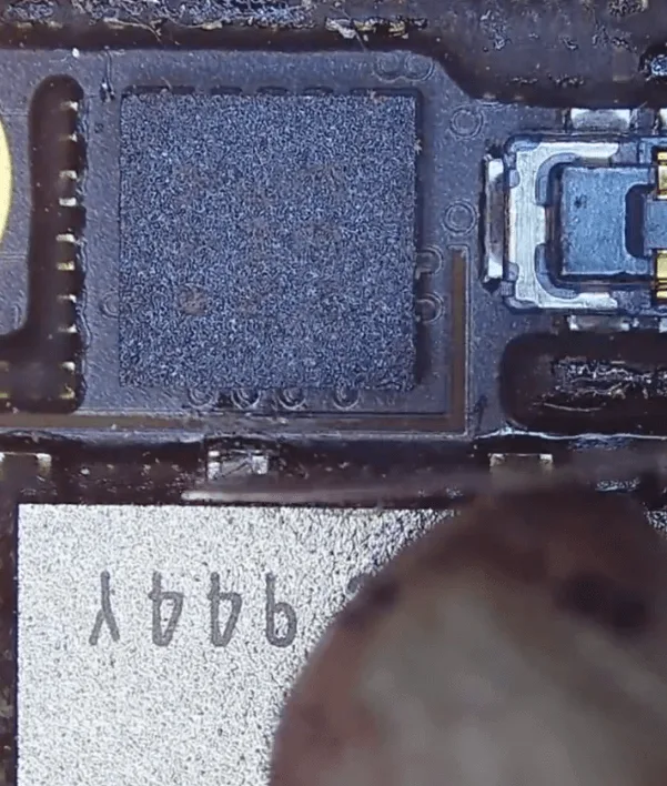
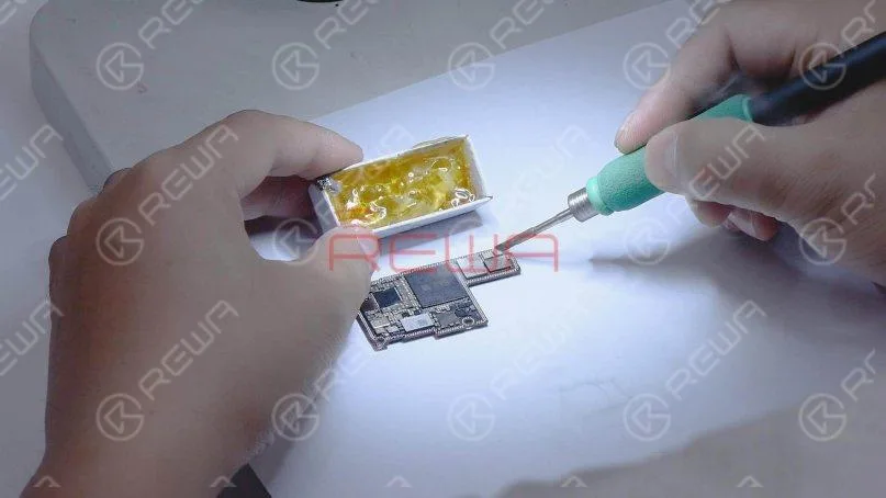
    • Carefully remove the black glue covering the NAND chip using a hot air gun and a blade knife.
    • Identify and remove the shorted capacitor, which is a filter-type capacitor. Since it’s a filter capacitor, it can be safely removed without replacement.

    Recheck the diode value on the rail after removing the capacitor, and confirm that it has returned to normal.

    2: Reassembling the Motherboard
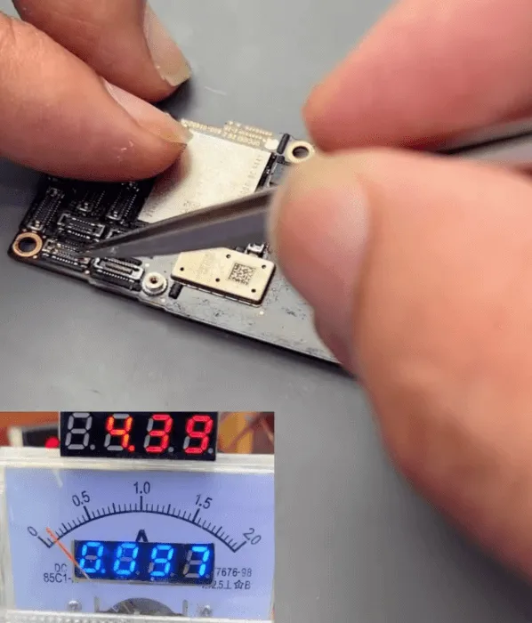
    • Connect the motherboard to the DC power supply and trigger the boot process again. This time, the boot current returns to normal.
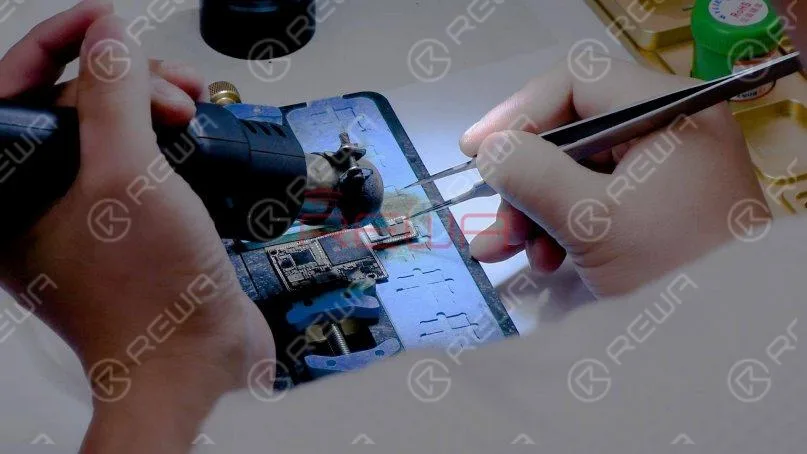
    • Recombine the two layers of the motherboard using a hot air gun, ensuring a proper fit.

    3: Final Assembly and Testing
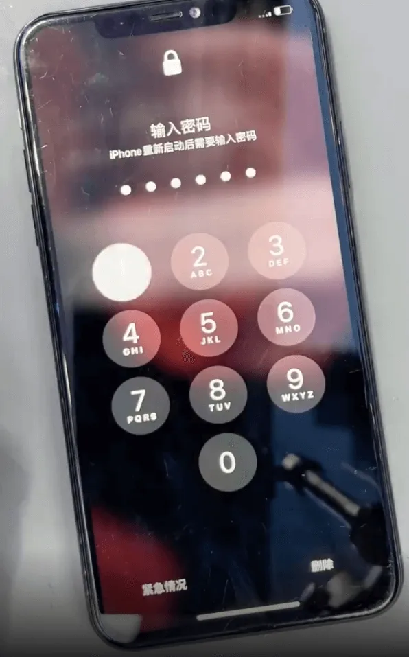
    iphone 11 pro max black screen no boot issue repair phone can be booted
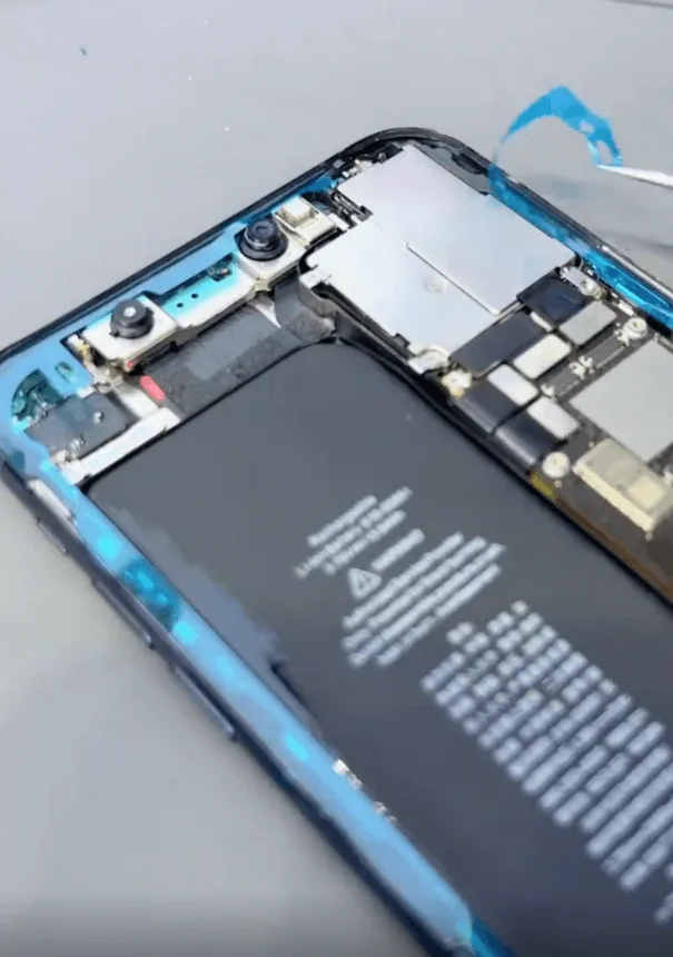
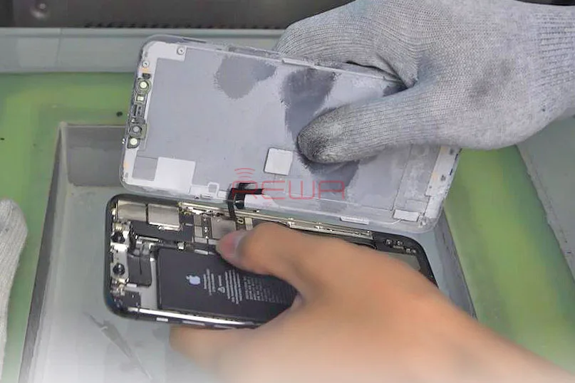
    • Reassemble the motherboard with the housing and other parts, taking care to install the waterproof seal sticker.
    • Assemble the screen and press the power button to conduct a final test.
    • After testing, all functions of the phone are working correctly. The no-boot issue has been successfully resolved by removing the shorted filter-type capacitor.

    Conclusion

    Repairing an iPhone 11 Pro Max that won’t boot due to a black screen can be a challenging task, but by following a systematic approach, the issue can be identified and resolved. In this case, removing a shorted capacitor from the NAND power supply rail restored the device to full functionality. For those facing similar issues, this guide provides a clear path to bring your device back to life. Stay tuned for more detailed repair guides to help you tackle even the most complex smartphone issues.
  • Troubleshooting iPhone 11 Pro Max No Service

    Troubleshooting iPhone 11 Pro Max No Service

    Recently, many repair technicians reported that they had received lots of iPhone 11 Pro Max with no service.

    Worse still, the fault could not be eliminated after replacing the signal board.

    Based on experience, REWA LAB technicians preliminarily conclude that the fault is likely on the signal pads of the logic board. Let’s check it out!

    Step 1: Fault analysis

    The motherboard has been repaired once.

    The original fault was no service but with the baseband modem firmware.

    The previous repair welded the baseband CPU and baseband EPROM to a good signal board.

    But the phone still had no service. It can be preliminarily judged that there are two possible faults.

    One is the damage of baseband CPU and baseband EPROM.

    The other is the damage of circuits related to the signal on the logic board.

    First of all, we install the motherboard on the phone to test.

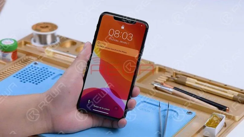
    The phone turns on normally but has no service.
    First of all, we install the motherboard on the phone to test. The phone turns on normally but has no service.

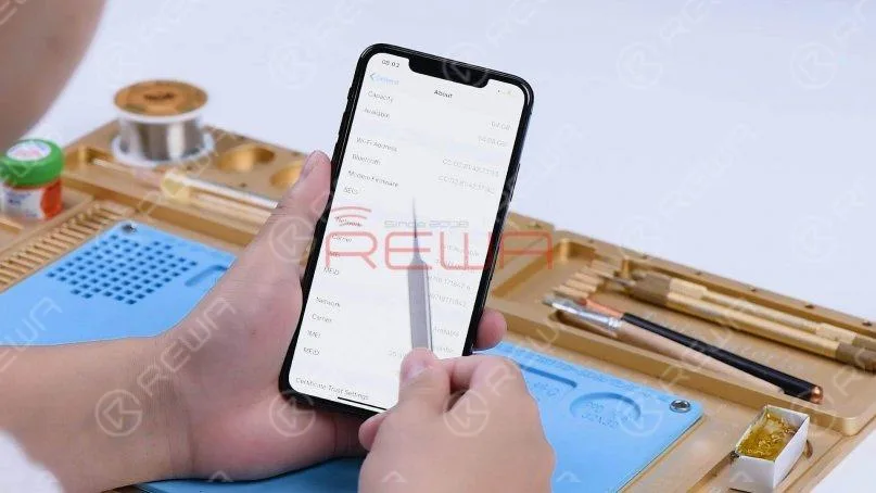
    Go to Settings, General, and About. We can see that the phone has no modem firmware.
    Go to Settings, General, and About. We can see that the phone has no modem firmware.

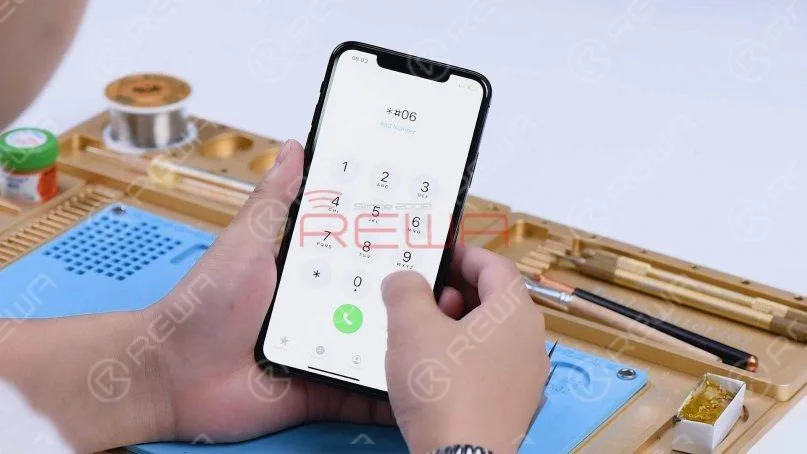
    Dial *#06# and the IMEI can’t be seen.

    Dial *#06# and the IMEI can’t be seen.

    The phone used to have modem firmware but now no longer has it. The cause may be related to pseudo soldering of the motherboard middle layer or damage of the baseband CPU and baseband EPROM.

    Step 2: Motherboard separation and troubleshooting

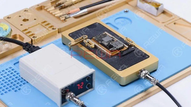
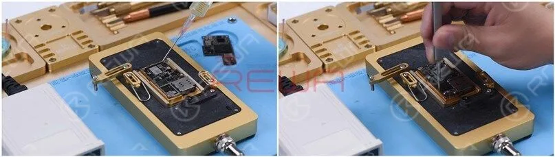
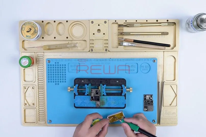
    Then we separate the motherboard to locate the faulty component. Put the motherboard on the Heating Platform and set the temperature to 185℃.

    Then we separate the motherboard to locate the faulty component. Put the motherboard on the Heating Platform and set the temperature to 185℃.

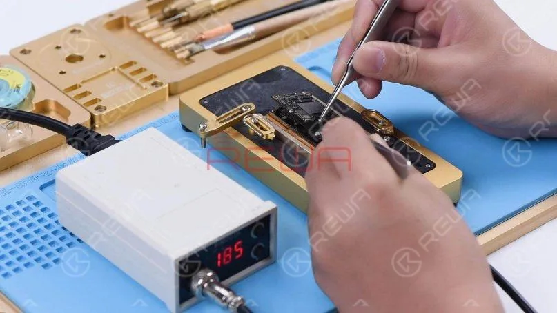
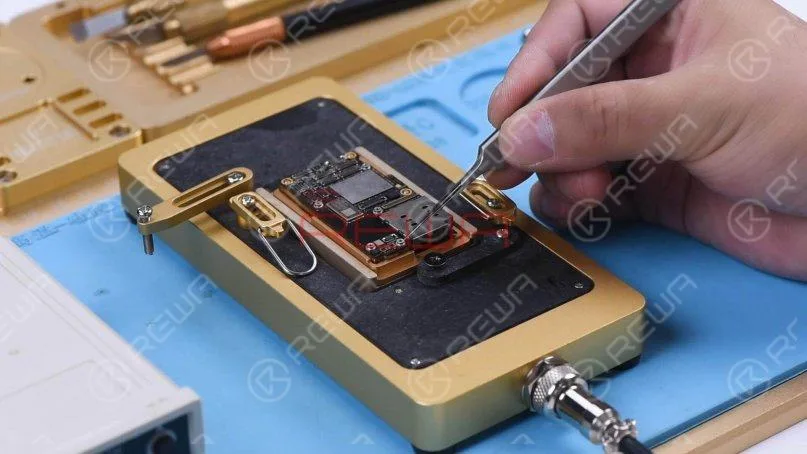
    When the temperature has risen to 185℃, remove the logic board with tweezers.
    When the temperature has risen to 185℃, remove the logic board with tweezers.

    Turn the power off and remove the signal board.

    Turn the power off and remove the signal board.

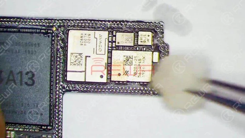
    Clean the logic board with PCB Cleaner.

    Since the signal board has been replaced, we need to check the logic board first.

    According to the test result, we can later determine whether the baseband CPU and EPROM are damaged.

    Clean the logic board with PCB Cleaner. Since the signal board has been replaced, we need to check the logic board first. According to the test result, we can later determine whether the baseband CPU and EPROM are damaged.

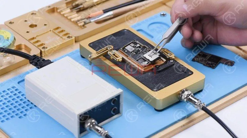
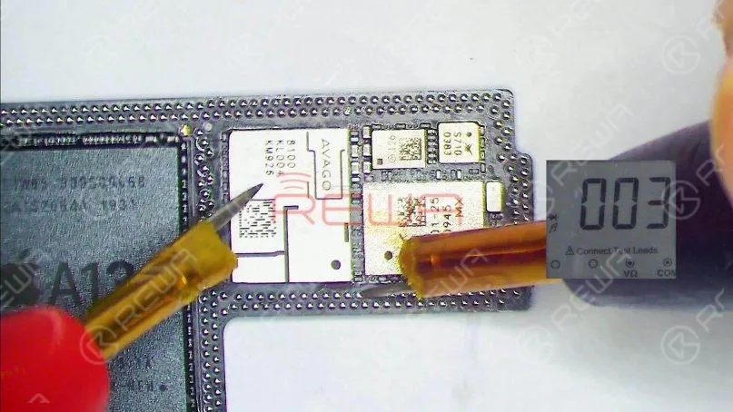
    Run diode mode measurement of the signal pads on the middle layer of the logic board.

    When measuring pin 131, the diode value is 003. The normal value should be around 400.

    Run diode mode measurement of the signal pads on the middle layer of the logic board. When measuring pin 131, the diode value is 003. The normal value should be around 400.

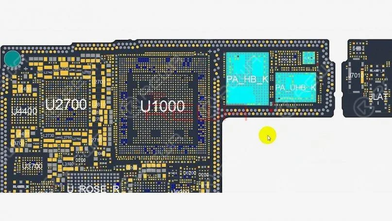
    Open the bitmap and many associated components are seen on the circuit.

    Open the bitmap and many associated components are seen on the circuit.

    Then we locate the faulty component with rosin detecting.

    Dip rosin with Soldering Iron at 365℃ and smoke some rosin on associated components.
    Then we locate the faulty component with rosin detecting. Dip rosin with Soldering Iron at 365℃ and smoke some rosin on associated components.

    Set the direct current supply to 1.8V. Connect the positive and negative anode of the direct current supply with multimeter probes.

    Set the direct current supply to 1.8V. Connect the positive and negative anode of the direct current supply with multimeter probes.

    Then connect the black probe to the ground and connect the red probe to pin 113 on the logic board. We can see rosin on a capacitor has melted.

    It indicates that the component is damaged. This circuit has multiple filter capacitors, so we can directly remove the damaged capacitor.
    Then connect the black probe to the ground and connect the red probe to pin 113 on the logic board. We can see rosin on a capacitor has melted. It indicates that the component is damaged. This circuit has multiple filter capacitors, so we can directly remove the damaged capacitor.

    Remove the capacitor with Hot Air Gun at 350℃ and airflow 3.

    Remove the capacitor with Hot Air Gun at 350℃ and airflow 3.

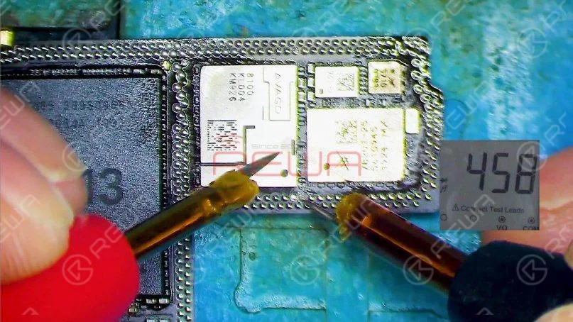
    Measure the logic board again after it has cooled. The diode value returns to a normal value of 458.
    Measure the logic board again after it has cooled. The diode value returns to a normal value of 458.

    Step 3: Motherboard restoration

    Next, we need to restore the motherboard.

    Firstly, we need to remove tin on the bonding pad of the motherboard.

    Smear rosin with Soldering Iron at 365℃ and solder-wick to remove tin on the bonding pad.

    Next, we need to restore the motherboard. Firstly, we need to remove tin on the bonding pad of the motherboard. Smear rosin with Soldering Iron at 365℃ and solder-wick to remove tin on the bonding pad.

    Remove tin on the signal board with the same method.

    After that, clean the logic board and signal board with PCB Cleaner.

    Next, attach the signal board to the Reballing Platform and put the Reballing Stencil in position.

    Apply a layer of medium-temperature Solder Paste evenly.
    Remove tin on the signal board with the same method. After that, clean the logic board and signal board with PCB Cleaner.Next, attach the signal board to the Reballing Platform and put the Reballing Stencil in position. Apply a layer of medium-temperature Solder Paste evenly.

    After reballing, put the signal board on the 185℃ Heating Platform to heat.

    When the solder balls are formed, turn the power off and cool the signal board.
    After reballing, put the signal board on the 185℃ Heating Platform to heat. When the solder balls are formed, turn the power off and cool the signal board.

    Apply some Paste Flux to the bonding pad of the signal board and align the logic board with the signal board.
    Apply some Paste Flux to the bonding pad of the signal board and align the logic board with the signal board.

    Keep heating the motherboard on the 185℃ Heating Platform.

    Push the logic board gently with tweezers and the logic board can return to the previous position.

    It shows that the motherboard has completed soldering.

    Keep heating the motherboard on the 185℃ Heating Platform. Push the logic board gently with tweezers and the logic board can return to the previous position. It shows that the motherboard has completed soldering.

    Turn the power off and cool the motherboard for 5 minutes.

    Then remove the motherboard and install it on the phone.

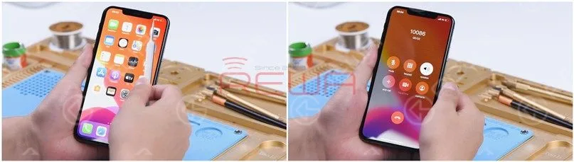
    The phone turns on normally and the 4G signal can be received.

    A phone call can also be made. The fault is cleared.

    Turn the power off and cool the motherboard for 5 minutes. Then remove the motherboard and install it on the phone. The phone turns on normally and the 4G signal can be received. A phone call can also be made. The fault is cleared.

    Summary

    The iPhone 11 Pro Max has been repaired once and still has no service after the baseband CPU and EPROM has been welded to a good signal board.

    It can be preliminarily judged that there are two possible faults. One is the damage of baseband CPU and baseband EPROM. The other is the damage of circuits related to the signal on the logic board.

    Through measuring the signal pads on the logic board and rosin detecting, a capacitor was found damaged.

    After removing the capacitor, the no service fault was cleared.

    We can rule out the possibility of baseband CPU and EPROM fault since the no service fault was eliminated after repairing the logic board.

    If you want to study more, please feel free to visit our academy for repair courses.

  • iPhone 11 Pro Max Screen Refurbishing – Detailed Operation

    iPhone 11 Pro Max Screen Refurbishing – Detailed Operation

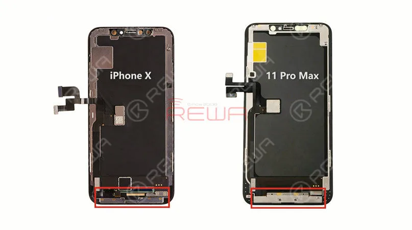
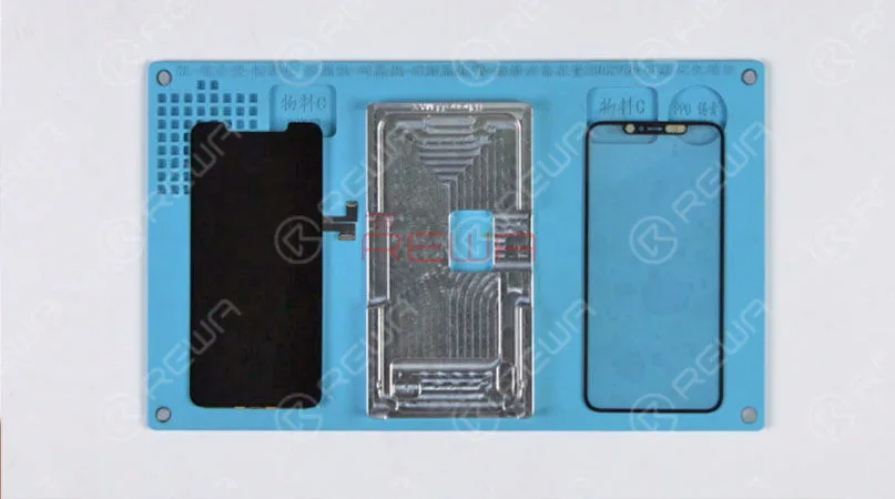
    For iPhone X and later iPhone models, the bracket covering the bottom flex cable bonding area is adhered by cold adhesive. The traditional method with heating assistance when removing bezel might damage the screen. After several attempts, REWA LAB found that the new method with cold assistance can improve the success rate and efficiency of screen refurbishing. Check our blog today for detailed operation process of iPhone 11 Pro Max screen refurbishing.
    For iPhone X and later iPhone models, the bracket covering the bottom flex cable bonding area is adhered by cold adhesive. The traditional method with heating assistance when removing bezel might damage the screen. After several attempts, REWA LAB found that the new method with cold assistance can improve the success rate and efficiency of screen refurbishing. Check our blog today for detailed operation process of iPhone 11 Pro Max screen refurbishing.

    The screen structure of iPhone 11 Pro Max is the same as that of iPhone X series. Therefore, the screen refurbishing process is also similar. Different from iPhone X series, the bracket covering the bottom flex cable bonding area of iPhone 11 Pro Max is relatively wide, which increases the difficulty of screen refurbishing. Therefore, we need to be extremely careful when removing the bezel.

    iPhone 11 Pro Max Screen Refurbishing

    Step 1 Screen Testing

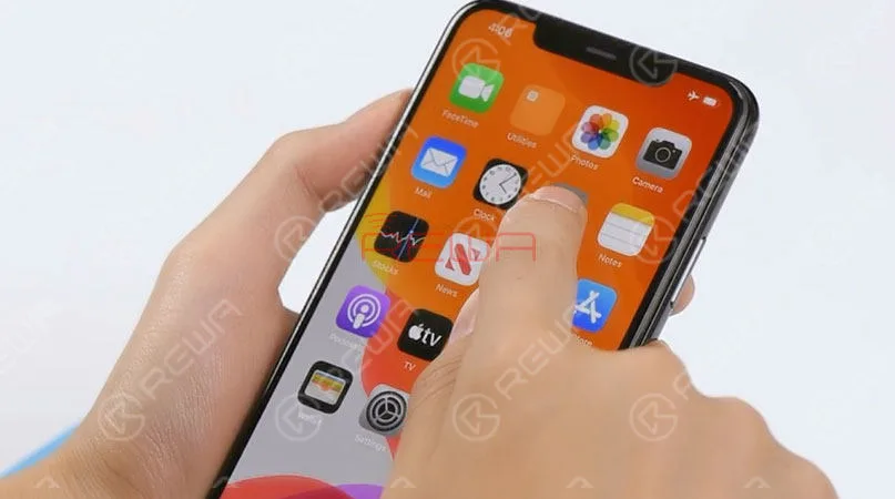
    The first thing we do is to test the screen. Test the display, touch functionality and Haptic Touch of the screen. All going well.
    The first thing we do is to test the screen. Test the display, touch functionality and Haptic Touch of the screen. All going well.

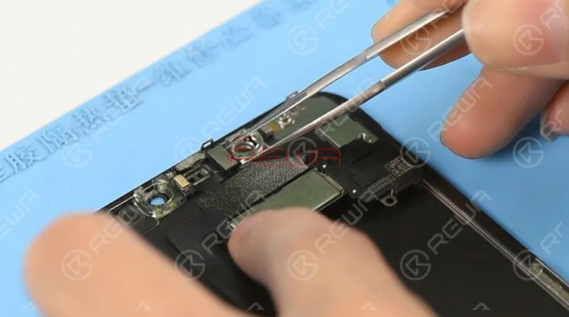
    Please be noted that when testing iPhone 11 Pro Max’s screen, the default brightness of the screen is set at the lowest level. To adjust brightness of the screen during the testing, we need to get the front panel sensor assembly flex cable connected. Disconnect the front panel sensor assembly flex cable and remove the OLED screen assembly. Then remove the front panel sensor assembly flex cable.
    Please be noted that when testing iPhone 11 Pro Max’s screen, the default brightness of the screen is set at the lowest level. To adjust brightness of the screen during the testing, we need to get the front panel sensor assembly flex cable connected. Disconnect the front panel sensor assembly flex cable and remove the OLED screen assembly. Then remove the front panel sensor assembly flex cable.

    Tips: it is not easy to remove the front panel sensor assembly flex cable, which can be easily damaged during the operation. And the damage can also affect the function of Face ID. So we need to be extremely careful when operating

    Step 2 Bezel Removing

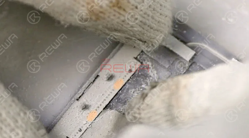
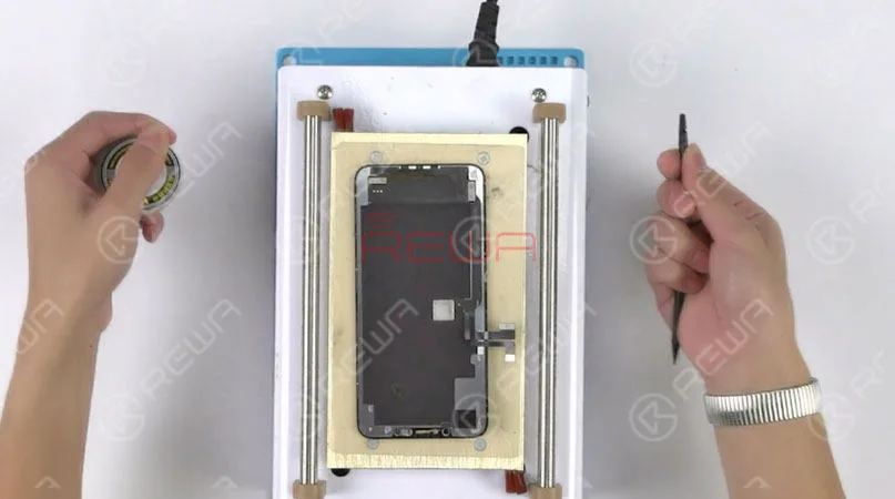
    Place the OLED screen assembly upside down into the -180℃ Frozen LCD Screen Separator. Insert a 0.06mm metal pry piece under the bracket covering the bottom flex cable bonding area. Slide back and forth to slice through the cold adhesive here. Once done, connect the screen and test. All going well.
    Place the OLED screen assembly upside down into the -180℃ Frozen LCD Screen Separator. Insert a 0.06mm metal pry piece under the bracket covering the bottom flex cable bonding area. Slide back and forth to slice through the cold adhesive here. Once done, connect the screen and test. All going well.

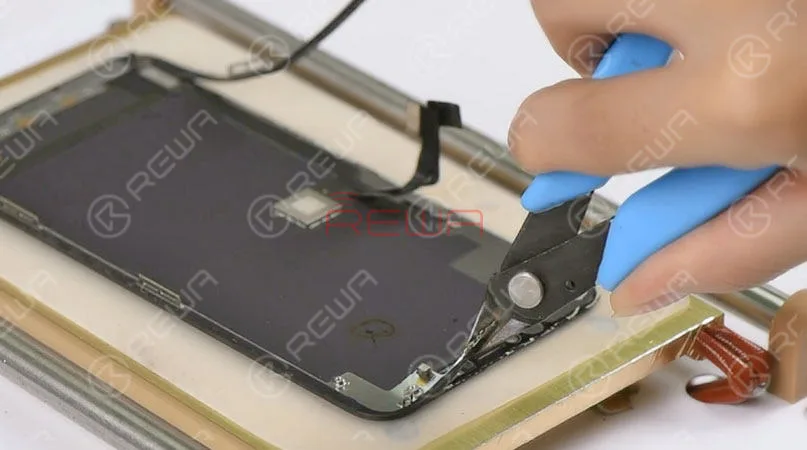
    Tips: since the front panel sensor assembly flex cable is not connected, the default brightness of the screen is set at the lowest level. Set temperature of the Heat Platform at 100℃. Then put the OLED Screen Assembly on the preheated platform. Press the ‘Start’ button to suck the screen. 1 minute later, remove the front camera and sensor holder. Cut out the top bracket with the Cutting Nipper. Then separate the bezel from the OLED with the Cutting Nipper.
    Tips: since the front panel sensor assembly flex cable is not connected, the default brightness of the screen is set at the lowest level. Set temperature of the Heat Platform at 100℃. Then put the OLED Screen Assembly on the preheated platform. Press the ‘Start’ button to suck the screen. 1 minute later, remove the front camera and sensor holder. Cut out the top bracket with the Cutting Nipper. Then separate the bezel from the OLED with the Cutting Nipper.

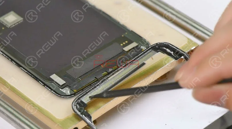
    Tips: when detaching the bezel at the bottom area of the phone, we need to insert the metal pry piece under the bracket covering the bottom flex cable bonding area and slide back and forth. This is to confirm that the cold adhesive here has been sliced open. The bezel has been removed completely. As you can see, the area here is adhered by cold adhesive in large amounts. To protect the OLED from damage, we’d better freeze the screen during the operation.
    Tips: when detaching the bezel at the bottom area of the phone, we need to insert the metal pry piece under the bracket covering the bottom flex cable bonding area and slide back and forth. This is to confirm that the cold adhesive here has been sliced open. The bezel has been removed completely. As you can see, the area here is adhered by cold adhesive in large amounts. To protect the OLED from damage, we'd better freeze the screen during the operation.

    Again, let’s test the OLED Screen Assembly. All going well.

    Step 3 Glass Lens Separating

    Now, let’s move to the glass lens separating process.

    Step 3 Glass Lens Separating   Now, let’s move to the glass lens separating process.

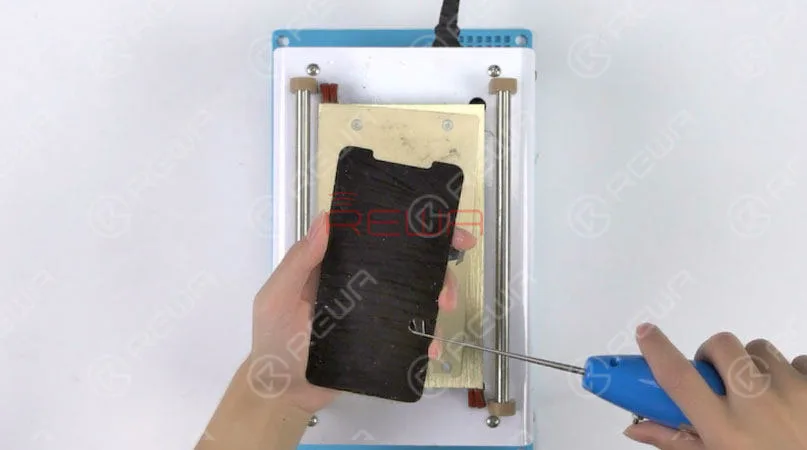
    Place the OLED Screen Assembly upside down on the Heat Platform. Remove residual glue on the earpiece speaker area with a blade. So that the Touch Panel will not be damaged when operating with the Cutting Wire. Next, separate the glass lens from OLED with Cutting Wire. Test again after separating. All going well.

    Step 4 OCA Glue Removing

    Let’s continue with OCA glue removing.

    Put the OLED screen upside down on the Heat Platform for 3 minutes. Make an incision with the Electric Glue Removing Device. Then continue to tear off the OCA Glue with one hand. Also, be careful with force applied. This is to avoid damaging the OLED screen. Once done, test the OLED Screen. All going well.

    Put the OLED screen upside down on the Heat Platform for 3 minutes. Make an incision with the Electric Glue Removing Device. Then continue to tear off the OCA Glue with one hand. Also, be careful with force applied. This is to avoid damaging the OLED screen. Once done, test the OLED Screen. All going well.

    Step 5 Laminating

    Tear off the protective film on the backside of the glass lens and attach the OCA to the right position of the glass lens. Then put the OCA attached glass lens into the bubble removing machine for 5 minutes. Once finished, take out the OCA attached glass lens.
    Tear off the protective film on the backside of the glass lens and attach the OCA to the right position of the glass lens. Then put the OCA attached glass lens into the bubble removing machine for 5 minutes. Once finished, take out the OCA attached glass lens.

    Now we need to laminate the OCA attached glass lens to the OLED Screen. Place the OLED screen into the OLED aligning mold. Clean the screen with the lint-free wiper. Tear off another layer of the OCA protective film and attach the OCA attached glass lens to the right position of the screen. Press gently to fit the glass lens with the screen. Place the mold upside down and take out the OLED Screen Assembly. Tear off the protective film on the glass lens. Cover the backside of the OLED Screen Assembly with a laminating sponge and then place the OLED Screen Assembly into the laminating machine. Choose ‘start’ on the LED panel. The machine starts to work. Laminating finished after several minutes. Again, let’s test the OLED Screen Assembly. All going well.

    Step 6 Bubble Removing

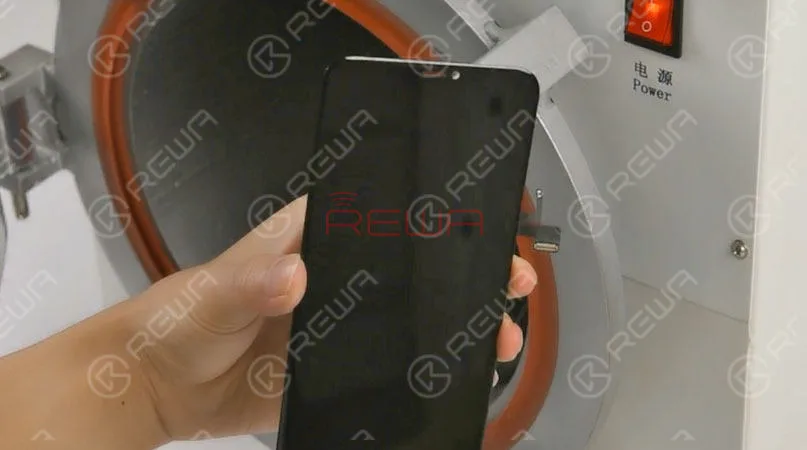
    Put the OLED Screen Assembly into Bubble Removing Machine for 10 minutes. Once finished, take out the OLED Screen Assembly.

    Put the OLED Screen Assembly into Bubble Removing Machine for 10 minutes. Once finished, take out the OLED Screen Assembly.

    Step 7 Bezel Attaching

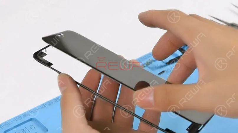
    Prepare a new piece of iPhone 11 Pro Max bezel. Tear off the protective film on the bezel. Apply the specialized glue to the bezel. Then apply pressure to fit the OLED Screen Assembly with the bezel.

    Prepare a new piece of iPhone 11 Pro Max bezel. Tear off the protective film on the bezel. Apply the specialized glue to the bezel. Then apply pressure to fit the OLED Screen Assembly with the bezel.

    Please be noted the FPC area on the bottom is very fragile. Be careful when operating. Otherwise, you might damage the OLED screen.
    Please be noted the FPC area on the bottom is very fragile. Be careful when operating. Otherwise, you might damage the OLED screen.

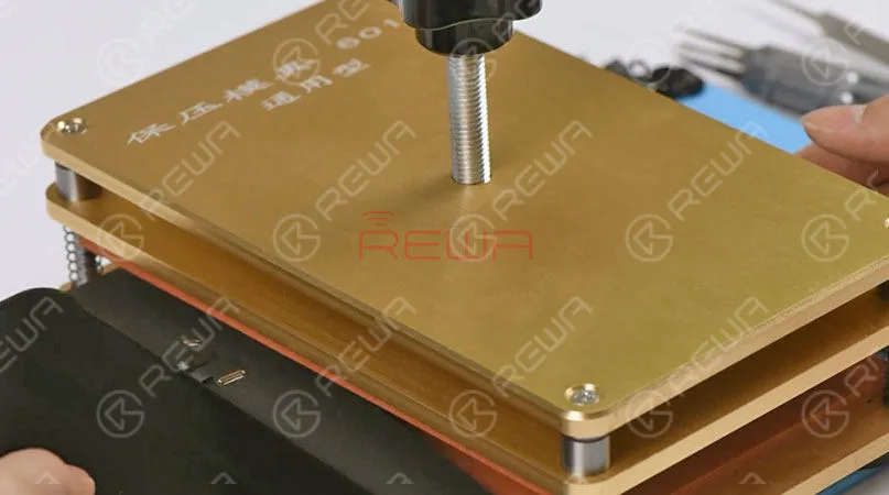
    Cover the backside of the OLED Screen Assembly with a laminating sponge. Then place the OLED Screen Assembly into the bezel laminating mold and fix it. Tighten the screw and wait for 10 minutes. Take out the OLED Screen Assembly afterwards.

    Step 8 Screen Testing

    Get the front camera and sensor holder installed, and then the earpiece speaker mesh. Get the front panel sensor assembly flex cable and the OLED Screen Assembly installed. Run function test – Display; Touch; Haptic Touch. Display, Touch, and Haptic Touch work normally.
    Get the front camera and sensor holder installed, and then the earpiece speaker mesh. Get the front panel sensor assembly flex cable and the OLED Screen Assembly installed. Run function test - Display; Touch; Haptic Touch. Display, Touch, and Haptic Touch work normally.

    iPhone 11 Pro Max screen refurbishing has been completed perfectly.

    Tools & Parts Used

    You can also visit REWA Youtube Channel  to check our video of iPhone 11 pro max refurbishing.

  • Turn iPhone 11 Pro Into iPhone 11 Pro Max

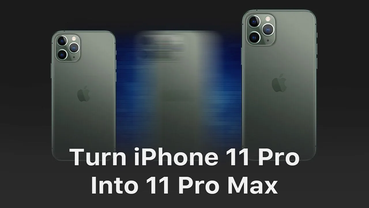
    Turn iPhone 11 Pro Into iPhone 11 Pro Max

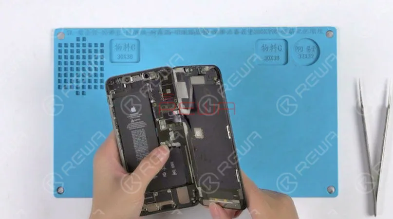
    Can iPhone 11 Pro possibly be turned into iPhone 11 Pro Max? It is actually theoretically possible. With pins of the two phones’ display connector and touch connector functioning almost the same, we can turn an iPhone 11 Pro into an iPhone 11 Pro Max by changing board ID resistors. Check our video now and find out how we finally made it.

    Warm Tips: This video is made for technique sharing only. For those who have no professional skills, please look before you leap.

    Tools & Parts used to separate iPhone 11 Pro: