Tag: scheda madre iphone

  • Separazione della scheda madre dell'iPhone 13 Pro

    Separazione della scheda madre dell'iPhone 13 Pro

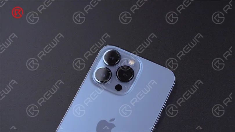
    Nel nostro ultimo post, abbiamo fatto un teardown dell'iPhone 13 Pro. Oggi separeremo la scheda madre dell'iPhone 13 Pro per condividere le differenze della scheda madre e le difficoltà di riparazione.
    Separazione della scheda madre dell'iPhone 13 Pro - La CPU più calda?

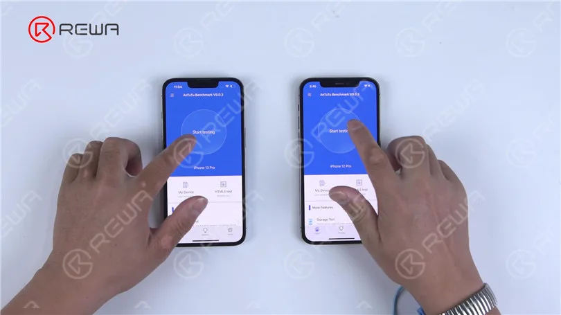
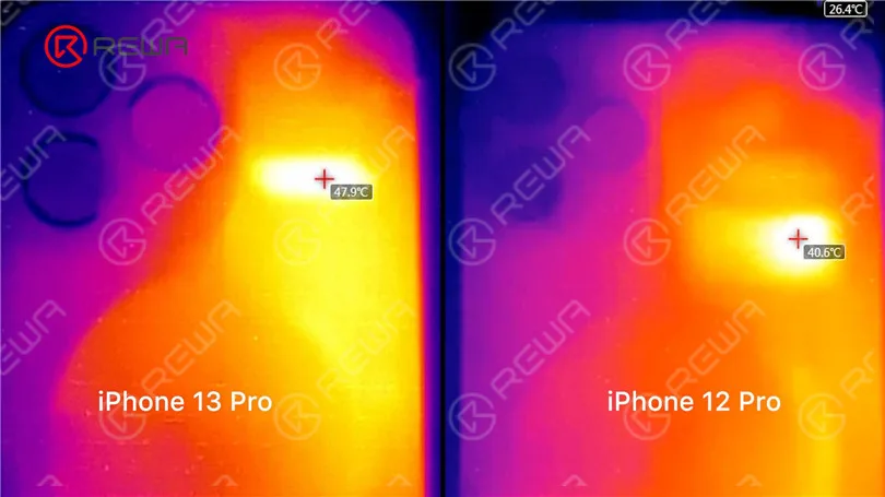
    In primo luogo, abbiamo effettuato un benchmark tra l'iPhone 13 Pro e l'iPhone 12 Pro allo stesso tempo. Grazie alla termocamera a infrarossi LINCSEEK, è emerso che l'iPhone 13 Pro è più caldo dell'iPhone 12 Pro.

    L'iPhone 13 Pro può raggiungere una temperatura massima di circa 48 °C, mentre la temperatura massima dell'iPhone 12 Pro si aggira intorno ai 40 °C.
    Separazione della scheda madre dell'iPhone 13 Pro - La CPU più calda?
    Separazione della scheda madre dell'iPhone 13 Pro - La CPU più calda?

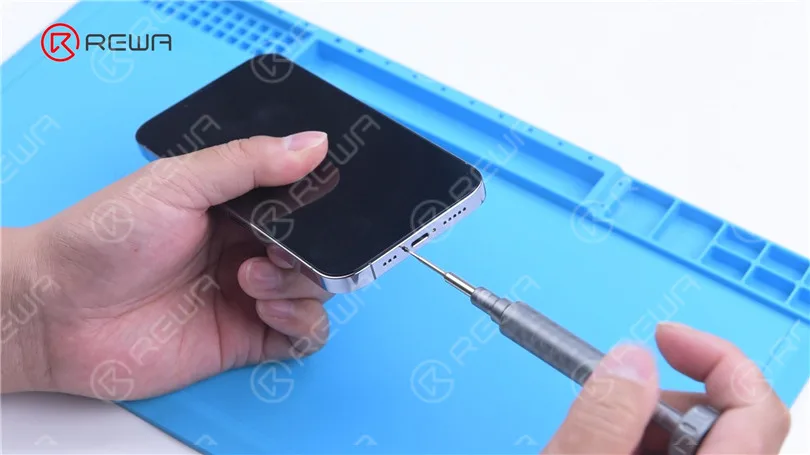
    Quindi separiamo la scheda madre dell'iPhone 13 Pro per visualizzarne la struttura interna e scoprire cosa ha causato il surriscaldamento. Nel frattempo, vi spiegheremo come separare e ricombinare la scheda madre.
    Separazione della scheda madre dell'iPhone 13 Pro - La CPU più calda?

    La scheda madre dell'iPhone 13 Pro è stata progettata per essere più compatta e lasciare più spazio alla batteria. Inoltre, la scheda madre non utilizza più un design a forma di "L".
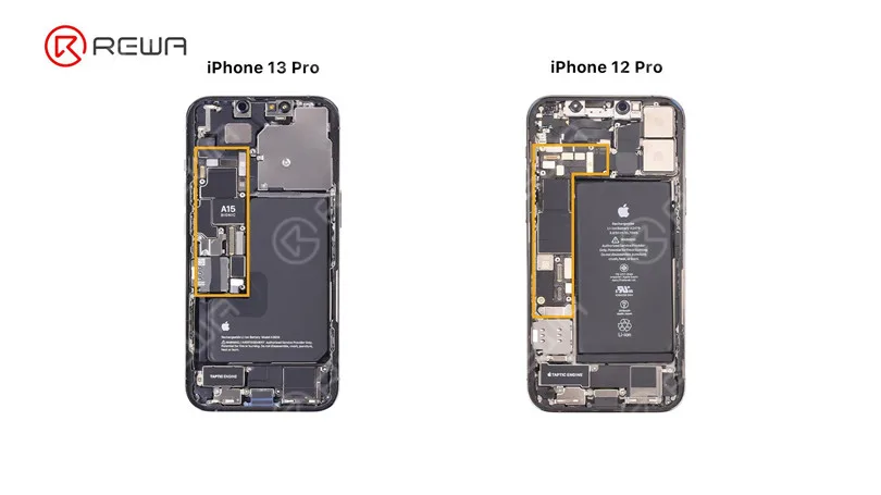
    Separazione della scheda madre dell'iPhone 13 Pro - La CPU più calda?

    Rimuovere la scheda madre. Il design a doppio strato è ancora utilizzato. Il lettore di schede SIM non è indipendente ed è saldato alla scheda madre.
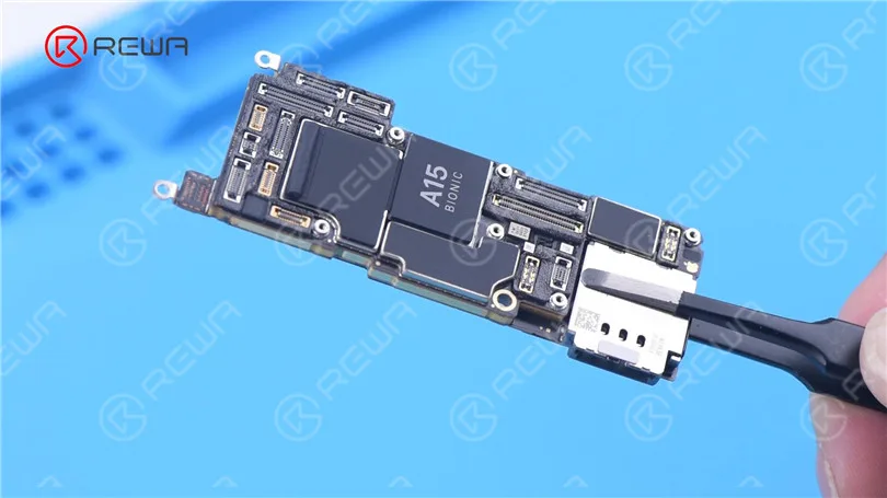
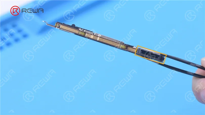
    Separazione della scheda madre dell'iPhone 13 Pro - La CPU più calda?
    Separazione della scheda madre dell'iPhone 13 Pro - La CPU più calda?

    Per una migliore dissipazione del calore, entrambi i lati della scheda madre sono ricoperti da spessi nastri per la dissipazione del calore.
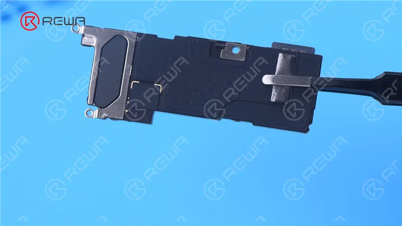
    Separazione della scheda madre dell'iPhone 13 Pro - La CPU più calda?

    Quindi rimuovere la schiuma sulla scheda madre. Rimuovere il nastro sulla scheda madre con la pistola ad aria calda a 100 °C. Si può notare che la NAND si trova sotto il nastro A15.
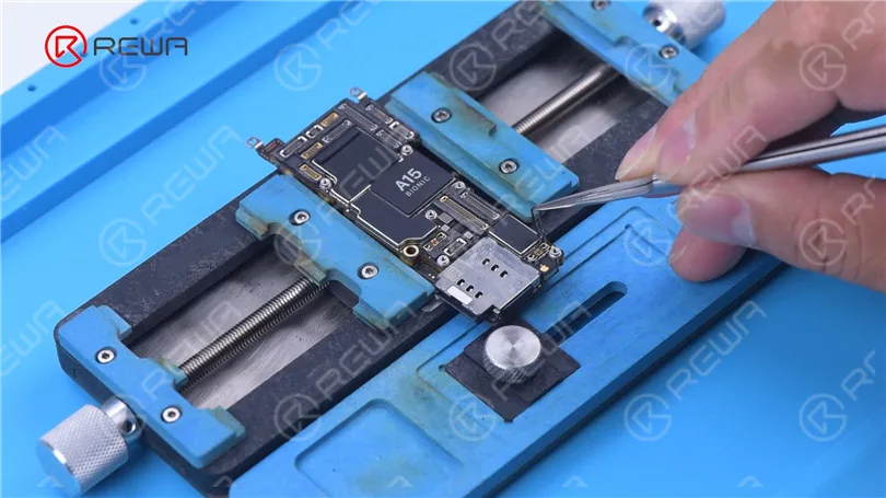
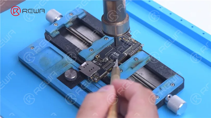
    Separazione della scheda madre dell'iPhone 13 Pro - La CPU più calda?
    Separazione della scheda madre dell'iPhone 13 Pro - La CPU più calda?

    Continuare a rimuovere i nastri sul retro della scheda madre. I nastri di dissipazione del calore sulla scheda madre sono riutilizzabili. Non danneggiare i nastri durante la riparazione per evitare di influenzare l'effetto di dissipazione del calore dopo il montaggio.
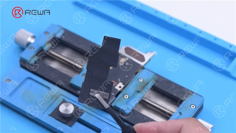
    Separazione della scheda madre dell'iPhone 13 Pro - La CPU più calda?

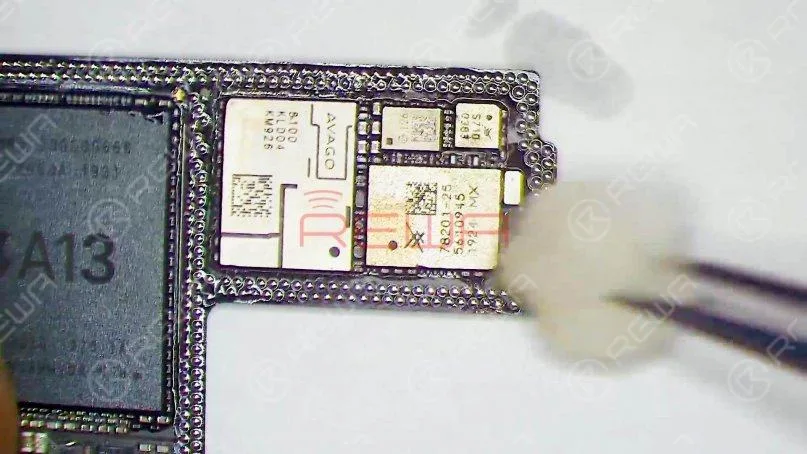
    Abbiamo scoperto che il retro della scheda di segnale dell'iPhone 13 Pro contiene dei componenti. Prestare attenzione a non danneggiare i componenti durante la separazione.
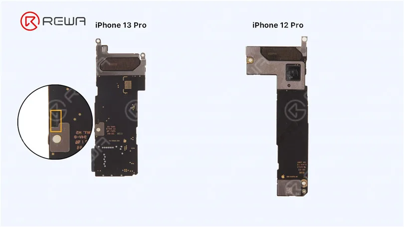
    Separazione della scheda madre dell'iPhone 13 Pro - La CPU più calda?

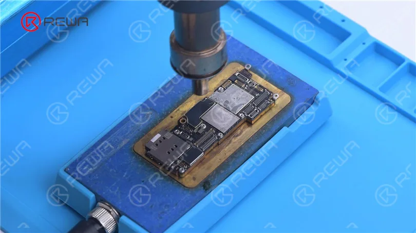
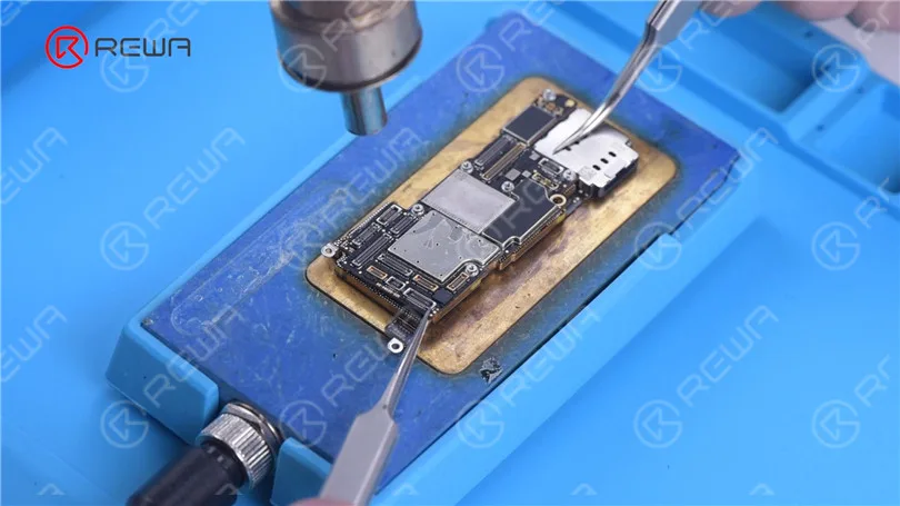
    Poiché la piattaforma di riscaldamento per l'iPhone 13 Pro non è ancora disponibile, utilizziamo una piattaforma di riscaldamento universale a 170 °C per la separazione.

    Perché lo strato centrale della scheda madre dell'iPhone 13 utilizza ancora pasta saldante a media temperatura per la saldatura.

    Aggiungere calore con la pistola ad aria calda a 330 °C intorno alla scheda madre, quando la temperatura della piattaforma di riscaldamento raggiunge i 150 °C. Quando la scheda logica si allenta, rimuoverla con una pinzetta.

    Non danneggiare i componenti circostanti durante la rimozione.
    Separazione della scheda madre dell'iPhone 13 Pro - La CPU più calda?

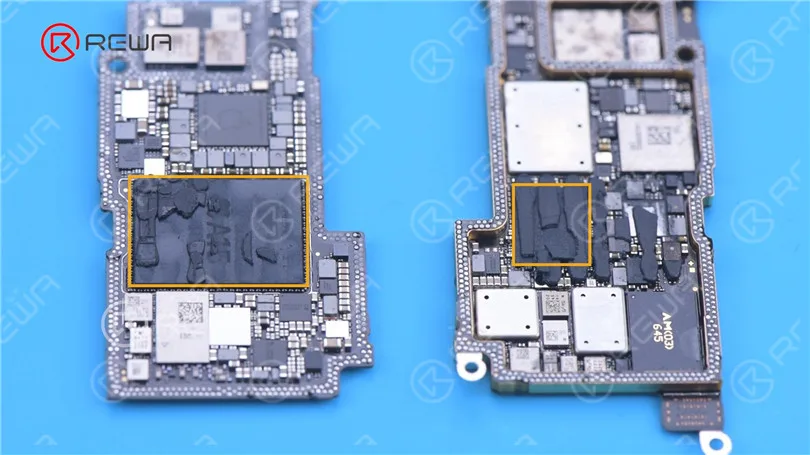
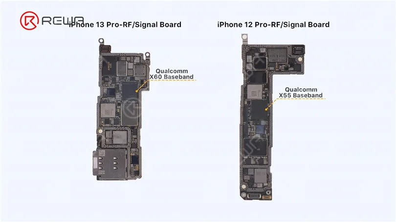
    La CPU è sovrapposta alla banda base, il che è negativo per la dissipazione del calore della scheda madre.
    Separazione della scheda madre dell'iPhone 13 Pro - La CPU più calda?

    Poi rimuoviamo il grasso termico sui chip.
    Separazione della scheda madre dell'iPhone 13 Pro - La CPU più calda?

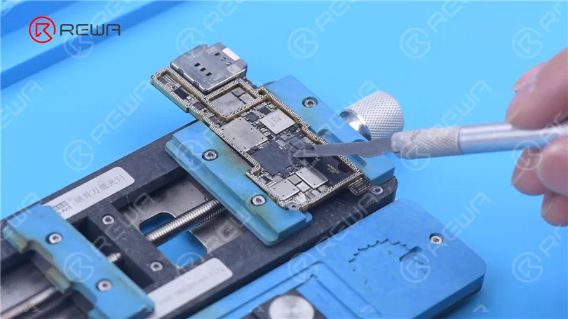
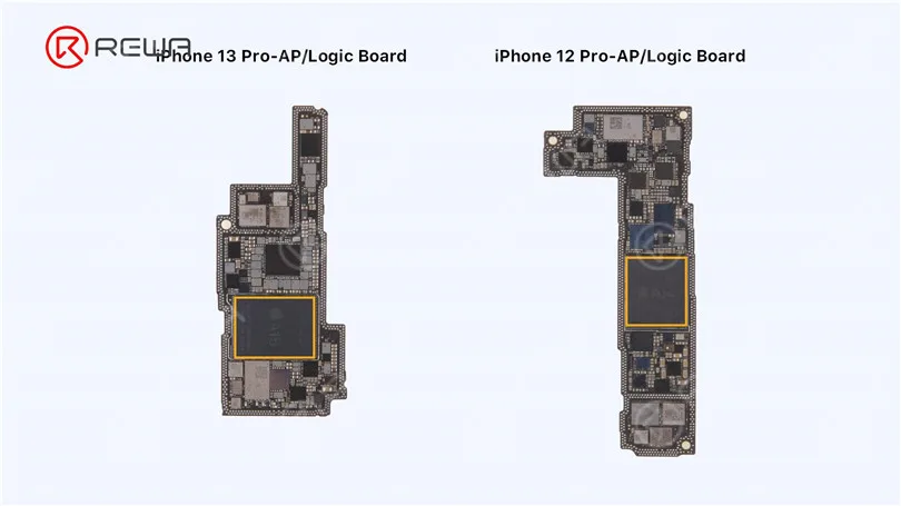
    Le dimensioni di A15 sono aumentate notevolmente, rendendo più difficile la dissaldatura della CPU.
    Separazione della scheda madre dell'iPhone 13 Pro - La CPU più calda?

    La CPU di baseband dell'iPhone 13 Pro è stata aggiornata con il Qualcomm X60. Si ritiene che il segnale del telefono sarà più stabile rispetto ai modelli precedenti. 
    Separazione della scheda madre dell'iPhone 13 Pro - La CPU più calda?

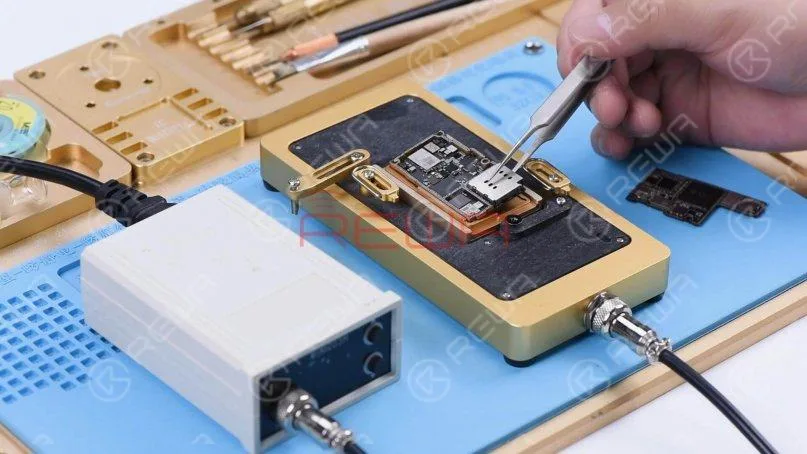
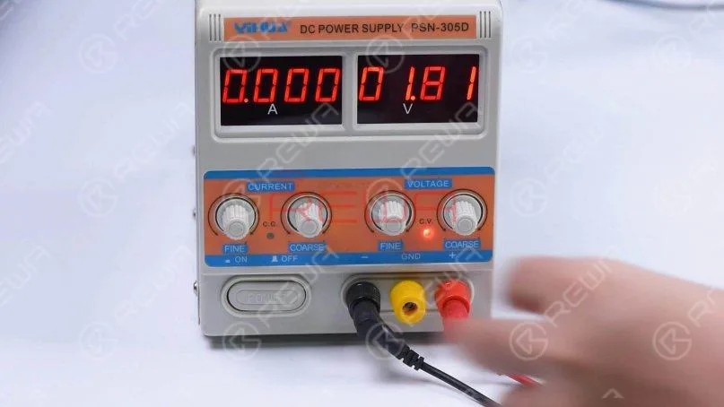
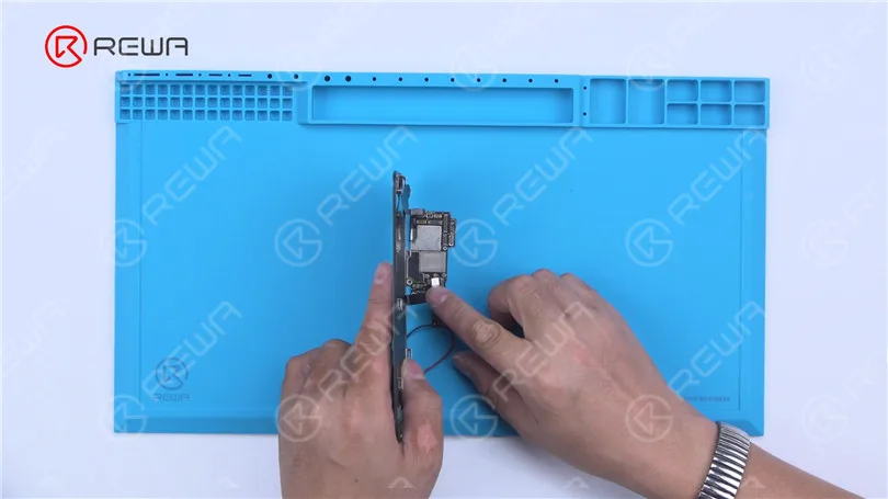
    Quindi vediamo se una singola scheda logica dell'iPhone 13 Pro è in grado di attivare l'avvio. Alimentare la scheda logica con un alimentatore a corrente continua.

    Collegare il display. Attivare l'avvio con una pinzetta.

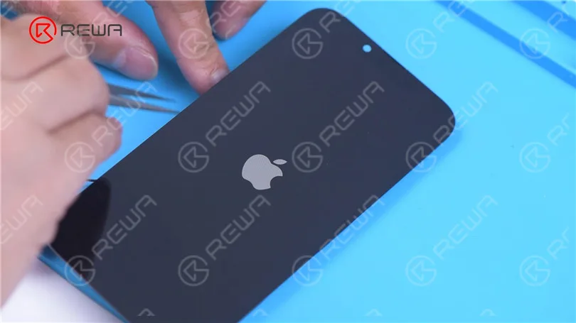
    Possiamo notare che l'iPhone 13 Pro ha impiegato più tempo per avviare il sistema rispetto ai modelli precedenti.

    Ci vogliono 8-10 secondi prima che il logo Apple appaia sullo schermo. Questo può essere causato dal sistema.
    Separazione della scheda madre dell'iPhone 13 Pro - La CPU più calda?
    Separazione della scheda madre dell'iPhone 13 Pro - La CPU più calda?

    Poi ricombiniamo la scheda dei segnali con la scheda logica.

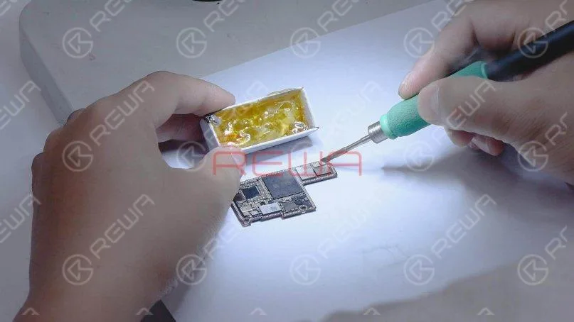
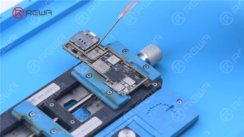
    Applicare un po' di Paste Flux sulle piazzole di collegamento della scheda dei segnali.

    Per pulire meglio lo stagno successivamente, applicare un po' di pasta saldante a bassa temperatura per neutralizzare la temperatura dei pad di incollaggio.
    Separazione della scheda madre dell'iPhone 13 Pro - La CPU più calda?

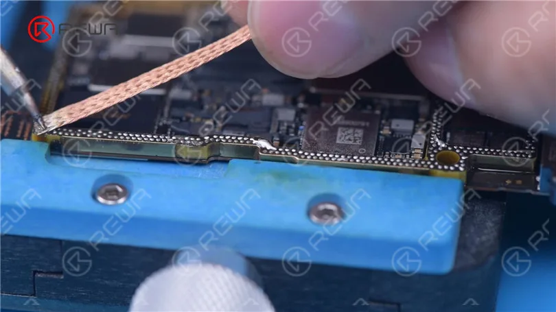
    Pulire le piazzole di incollaggio con il saldatore a 380 °C e lo stoppino per saldare.

    Applicare la pasta saldante sulle piazzole di incollaggio della scheda logica.

    Non toccare i componenti circostanti durante l'applicazione della pasta saldante.

    Questo aspetto va tenuto presente anche quando si utilizza il saldatore per rimuovere lo stagno.
    Separazione della scheda madre dell'iPhone 13 Pro - La CPU più calda?

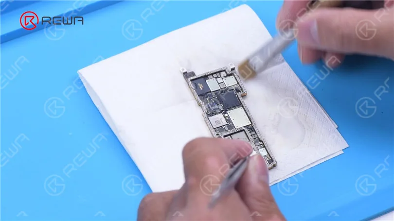
    Pulire i pad di collegamento con PCB Cleaner.
    Separazione della scheda madre dell'iPhone 13 Pro - La CPU più calda?

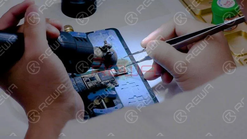
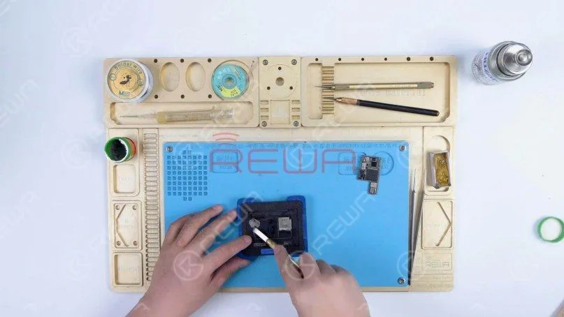
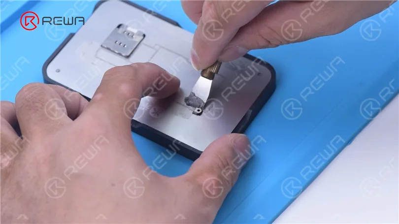
    Quindi si procede al reballing della scheda di segnalazione. Fissare il pannello di segnalazione alla piattaforma di reballing.

    Posizionare lo stencil di reballing. Applicare uniformemente la pasta saldante a media temperatura.
    Separazione della scheda madre dell'iPhone 13 Pro - La CPU più calda?

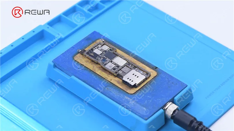
    Rimuovere lo stencil di reballing. Mettere la scheda di segnale sulla piattaforma di riscaldamento per riscaldarla.

    Dopo la formazione delle sfere di saldatura, raffreddare la scheda di segnale.
    Separazione della scheda madre dell'iPhone 13 Pro - La CPU più calda?

    Applicare un po' di Paste Flux sui pad di incollaggio.

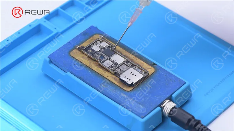
    Allineare la scheda logica con la scheda dei segnali.

    Continuare a riscaldare con la Piattaforma di riscaldamento a 170 °C.

    Aggiungere calore intorno alla scheda madre con la pistola ad aria calda a 330 °C.
    Separazione della scheda madre dell'iPhone 13 Pro - La CPU più calda?
    Separazione della scheda madre dell'iPhone 13 Pro - La CPU più calda?

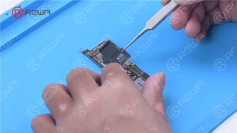
    Dopo che la scheda madre si è raffreddata, staccarla.

    Riattaccare i nastri di schiuma e di dissipazione del calore alla scheda madre.
    Separazione della scheda madre dell'iPhone 13 Pro - La CPU più calda?

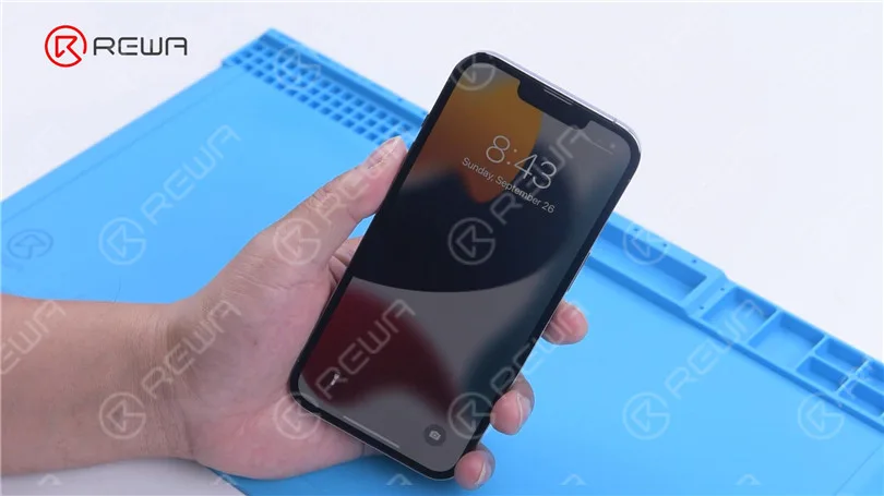
    Installare la scheda madre per il test. Il telefono si accende normalmente.
    Separazione della scheda madre dell'iPhone 13 Pro - La CPU più calda?

    In sintesi, attraverso questa separazione, si scopre che l'iPhone 13 Pro ha ancora una scheda madre a doppio strato.

    La scheda madre presenta alcuni cambiamenti nell'aspetto, ma la distribuzione dei chip principali è rimasta invariata.

    Inoltre, la CPU e la banda base sono impilate, il che non solo aumenta la difficoltà di riparazione, ma fa anche sì che la scheda madre si riscaldi facilmente.

    In determinate condizioni, è più probabile che la scheda madre presenti dei problemi.
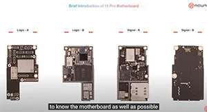
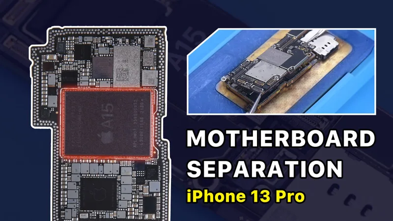
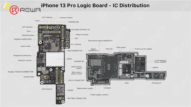
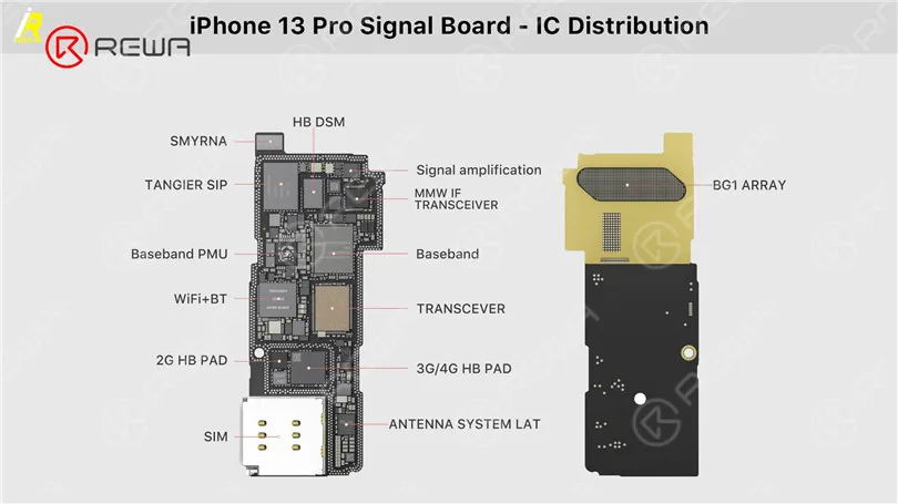
    Per riferimento, questo è il diagramma di distribuzione del chip della scheda madre dell'iPhone 13 Pro di iRepair.
    Separazione della scheda madre dell'iPhone 13 Pro - La CPU più calda?
    Separazione della scheda madre dell'iPhone 13 Pro - La CPU più calda?
  • iPhone 11 Pro Motherboard Chips Distribution | REWA Academy

    iPhone 11 Pro Motherboard Chips Distribution | REWA Academy

    Some repair technicians repair motherboards according to experience and thus the repair result cannot be guaranteed. Only when you comprehend the phone working principles can the motherboard problems be fully resolved. REWA Academy is about to launch the iPhone 11 Pro motherboard repair online course, providing technicians with systematic motherboard repair knowledge.

  • Risoluzione dei problemi di iPhone 11 Pro Max senza servizio

    Risoluzione dei problemi di iPhone 11 Pro Max senza servizio

    Recently, many repair technicians reported that they had received lots of iPhone 11 Pro Max with no service.

    Worse still, the fault could not be eliminated after replacing the signal board.

    Based on experience, REWA LAB technicians preliminarily conclude that the fault is likely on the signal pads of the logic board. Let’s check it out!

    Step 1: Fault analysis

    The motherboard has been repaired once.

    The original fault was no service but with the baseband modem firmware.

    The previous repair welded the baseband CPU and baseband EPROM to a good signal board.

    But the phone still had no service. It can be preliminarily judged that there are two possible faults.

    One is the damage of baseband CPU and baseband EPROM.

    The other is the damage of circuits related to the signal on the logic board.

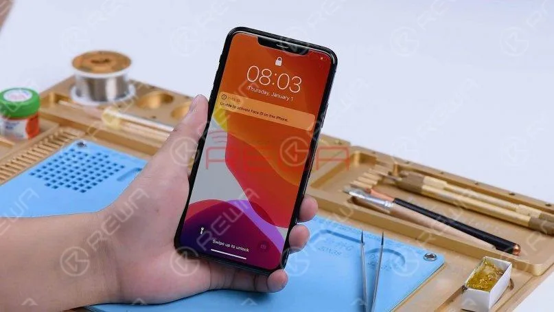
    First of all, we install the motherboard on the phone to test.

    The phone turns on normally but has no service.
    First of all, we install the motherboard on the phone to test. The phone turns on normally but has no service.

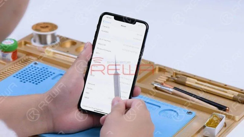
    Go to Settings, General, and About. We can see that the phone has no modem firmware.
    Go to Settings, General, and About. We can see that the phone has no modem firmware.

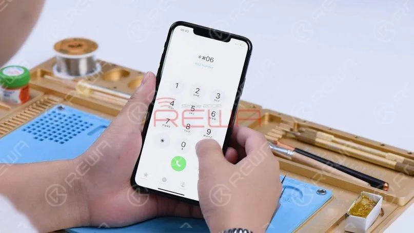
    Dial *#06# and the IMEI can’t be seen.

    Dial *#06# and the IMEI can’t be seen.

    The phone used to have modem firmware but now no longer has it. The cause may be related to pseudo soldering of the motherboard middle layer or damage of the baseband CPU and baseband EPROM.

    Step 2: Motherboard separation and troubleshooting

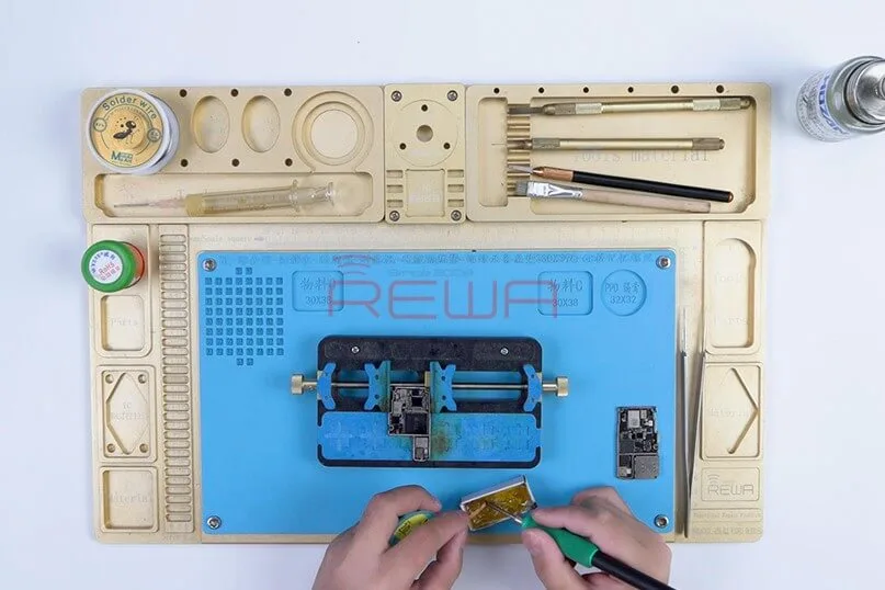
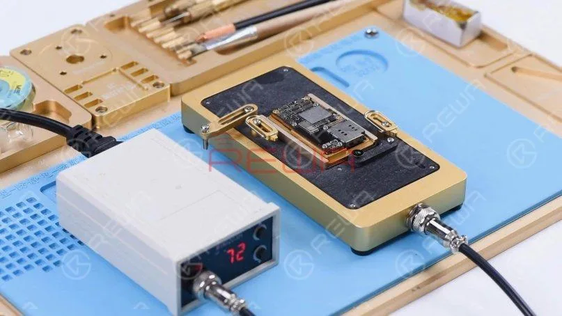
    Then we separate the motherboard to locate the faulty component. Put the motherboard on the Piattaforma di riscaldamento and set the temperature to 185℃.

    Then we separate the motherboard to locate the faulty component. Put the motherboard on the Heating Platform and set the temperature to 185℃.

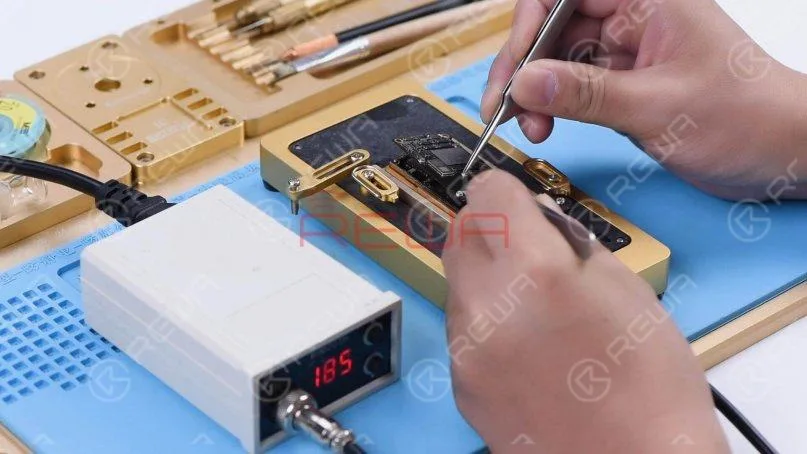
    When the temperature has risen to 185℃, remove the logic board with tweezers.
    When the temperature has risen to 185℃, remove the logic board with tweezers.

    Turn the power off and remove the signal board.

    Turn the power off and remove the signal board.

    Clean the logic board with PCB Cleaner.

    Since the signal board has been replaced, we need to check the logic board first.

    According to the test result, we can later determine whether the baseband CPU and EPROM are damaged.

    Clean the logic board with PCB Cleaner. Since the signal board has been replaced, we need to check the logic board first. According to the test result, we can later determine whether the baseband CPU and EPROM are damaged.

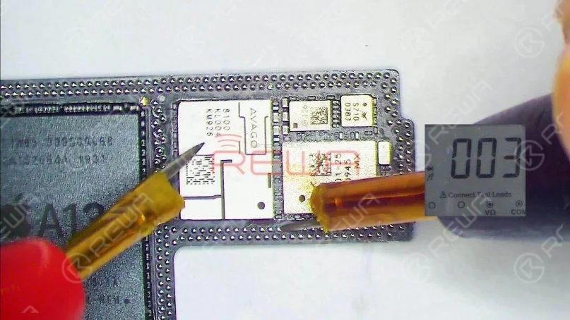
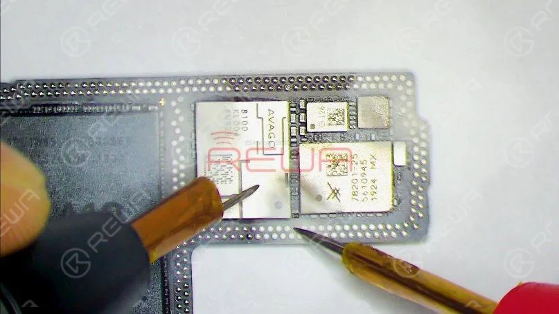
    Run diode mode measurement of the signal pads on the middle layer of the logic board.

    When measuring pin 131, the diode value is 003. The normal value should be around 400.

    Run diode mode measurement of the signal pads on the middle layer of the logic board. When measuring pin 131, the diode value is 003. The normal value should be around 400.

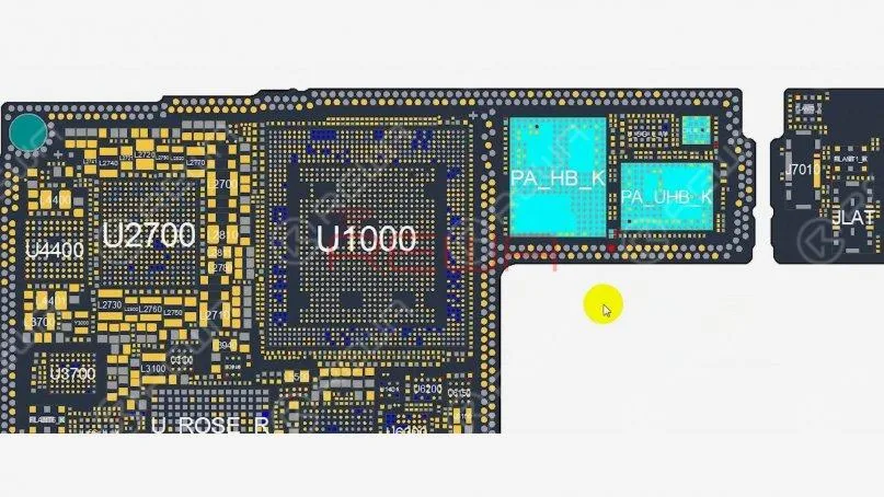
    Open the bitmap and many associated components are seen on the circuit.

    Open the bitmap and many associated components are seen on the circuit.

    Then we locate the faulty component with rosin detecting.

    Dip rosin with Soldering Iron at 365℃ and smoke some rosin on associated components.
    Then we locate the faulty component with rosin detecting. Dip rosin with Soldering Iron at 365℃ and smoke some rosin on associated components.

    Set the direct current supply to 1.8V. Connect the positive and negative anode of the direct current supply with multimeter probes.
    Set the direct current supply to 1.8V. Connect the positive and negative anode of the direct current supply with multimeter probes.

    Then connect the black probe to the ground and connect the red probe to pin 113 on the logic board. We can see rosin on a capacitor has melted.

    It indicates that the component is damaged. This circuit has multiple filter capacitors, so we can directly remove the damaged capacitor.
    Then connect the black probe to the ground and connect the red probe to pin 113 on the logic board. We can see rosin on a capacitor has melted. It indicates that the component is damaged. This circuit has multiple filter capacitors, so we can directly remove the damaged capacitor.

    Remove the capacitor with Pistola ad aria calda at 350℃ and airflow 3.

    Remove the capacitor with Hot Air Gun at 350℃ and airflow 3.

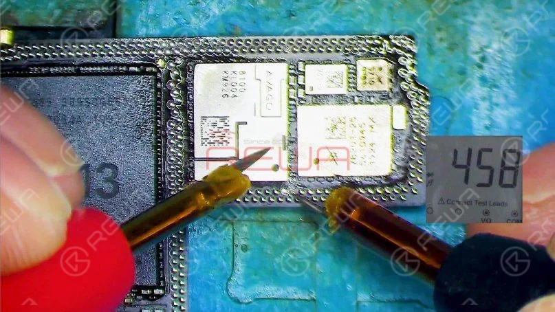
    Measure the logic board again after it has cooled. The diode value returns to a normal value of 458.
    Measure the logic board again after it has cooled. The diode value returns to a normal value of 458.

    Step 3: Motherboard restoration

    Next, we need to restore the motherboard.

    Firstly, we need to remove tin on the bonding pad of the motherboard.

    Smear rosin with Soldering Iron at 365℃ and solder-wick to remove tin on the bonding pad.

    Next, we need to restore the motherboard. Firstly, we need to remove tin on the bonding pad of the motherboard. Smear rosin with Soldering Iron at 365℃ and solder-wick to remove tin on the bonding pad.

    Remove tin on the signal board with the same method.

    After that, clean the logic board and signal board with PCB Cleaner.

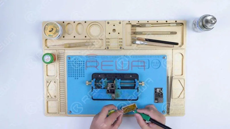
    Next, attach the signal board to the Reballing Platform and put the Reballing Stencil in position.

    Apply a layer of medium-temperature Solder Paste evenly.
    Remove tin on the signal board with the same method. After that, clean the logic board and signal board with PCB Cleaner.Next, attach the signal board to the Reballing Platform and put the Reballing Stencil in position. Apply a layer of medium-temperature Solder Paste evenly.

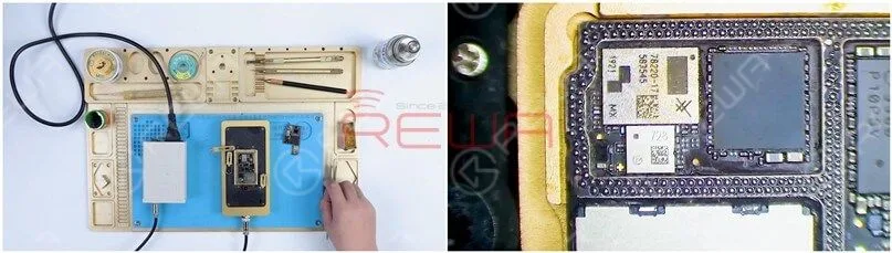
    After reballing, put the signal board on the 185℃ Heating Platform to heat.

    When the solder balls are formed, turn the power off and cool the signal board.
    After reballing, put the signal board on the 185℃ Heating Platform to heat. When the solder balls are formed, turn the power off and cool the signal board.

    Applicare alcuni Flusso di pasta to the bonding pad of the signal board and align the logic board with the signal board.
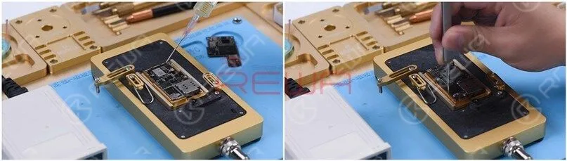
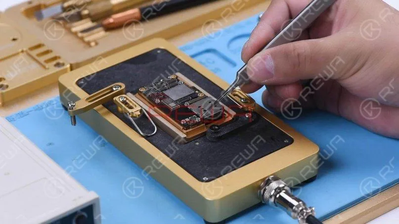
    Apply some Paste Flux to the bonding pad of the signal board and align the logic board with the signal board.

    Keep heating the motherboard on the 185℃ Heating Platform.

    Push the logic board gently with tweezers and the logic board can return to the previous position.

    It shows that the motherboard has completed soldering.

    Keep heating the motherboard on the 185℃ Heating Platform. Push the logic board gently with tweezers and the logic board can return to the previous position. It shows that the motherboard has completed soldering.

    Turn the power off and cool the motherboard for 5 minutes.

    Then remove the motherboard and install it on the phone.

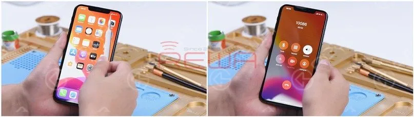
    The phone turns on normally and the 4G signal can be received.

    A phone call can also be made. The fault is cleared.

    Turn the power off and cool the motherboard for 5 minutes. Then remove the motherboard and install it on the phone. The phone turns on normally and the 4G signal can be received. A phone call can also be made. The fault is cleared.

    Sintesi

    The iPhone 11 Pro Max has been repaired once and still has no service after the baseband CPU and EPROM has been welded to a good signal board.

    It can be preliminarily judged that there are two possible faults. One is the damage of baseband CPU and baseband EPROM. The other is the damage of circuits related to the signal on the logic board.

    Through measuring the signal pads on the logic board and rosin detecting, a capacitor was found damaged.

    After removing the capacitor, the no service fault was cleared.

    We can rule out the possibility of baseband CPU and EPROM fault since the no service fault was eliminated after repairing the logic board.

    Se desideri approfondire i tuoi studi, non esitare a visitare il nostro accademia per corsi di riparazione.