Tag: saldatura

  • How iPhone Aftermarket Battery BMS Boards Are Made

    How iPhone Aftermarket Battery BMS Boards Are Made

    When choosing an iPhone aftermarket battery, the BMS board (Battery Management System board) plays an important role in battery performance. So, what makes a third-party battery board reliable?

    In this article, REWA Lab takes you to explore how an iPhone aftermarket battery BMS board is manufactured, from bare PCB assembly and TI chip placement to firmware programming, functional testing, battery cell assembly, and final strict quality inspection.
    how iphone aftermarket battery bms boards made the crucial stages to

    What Is an iPhone Battery BMS Board?

    The BMS board is the control and protection system of a rechargeable battery, helping monitor the battery and protect it during charging and use.

    For an aftermarket iPhone battery, the BMS board works alongside the battery cell. While the cell stores the electrical energy, the BMS board manages and monitors important battery-related functions.
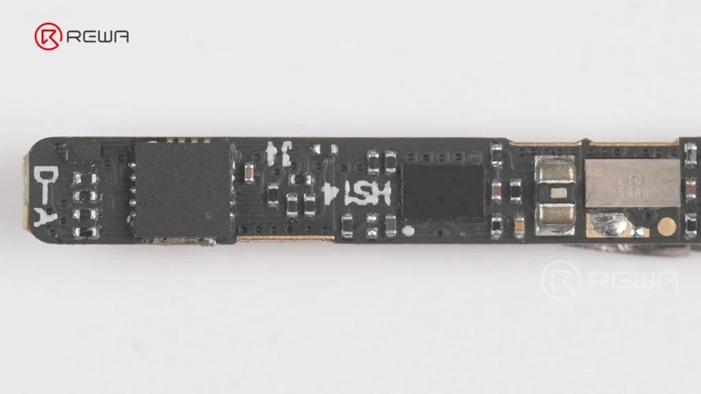
    Close-up view of a populated black iPhone battery BMS circuit board with surface-mounted chips and electronic components

    Depending on the design, a battery BMS board can help with functions such as:

    • Battery voltage & current monitoring
    • Temperature-related protection
    • Overcharge & short-circuit protection
    • Battery data and state-of-charge estimation
    • Communication between the battery and device

    This is why two aftermarket batteries using cells with similar specifications can still have different real-world performance and reliability.

    Step 1: Bare PCB Preparation and SMT Assembly

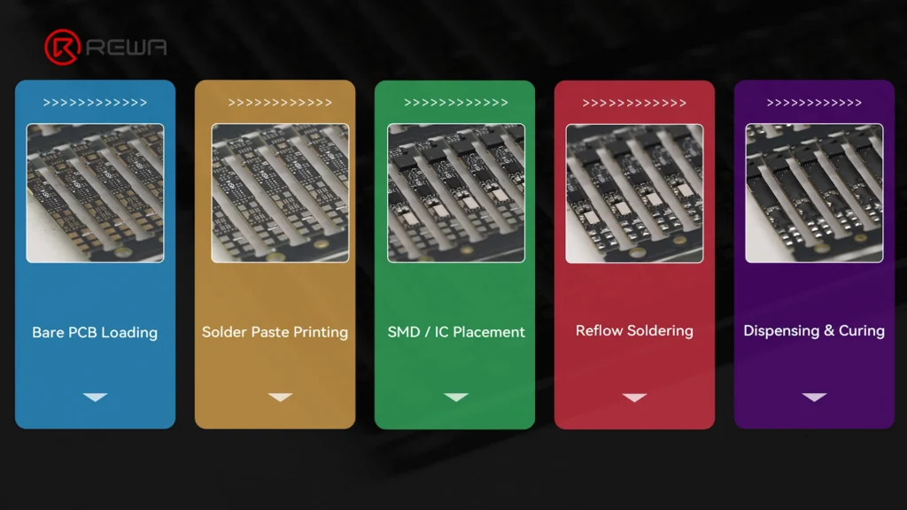
    The manufacturing process starts with a bare PCB, which is the foundation of the BMS board. Before production begins, the factory receives bare PCBs that have already passed IQC inspection and loads them onto SMT feeder racks for automated component placement.

    In poche parole:

    SMT stands for Surface Mount Technology. It is a manufacturing method that places tiny electronic components directly onto the surface of a circuit board.

    The basic process begins with solder paste printing. The PCB is positioned against a stencil, and solder paste is applied to precisely defined positions on the board.
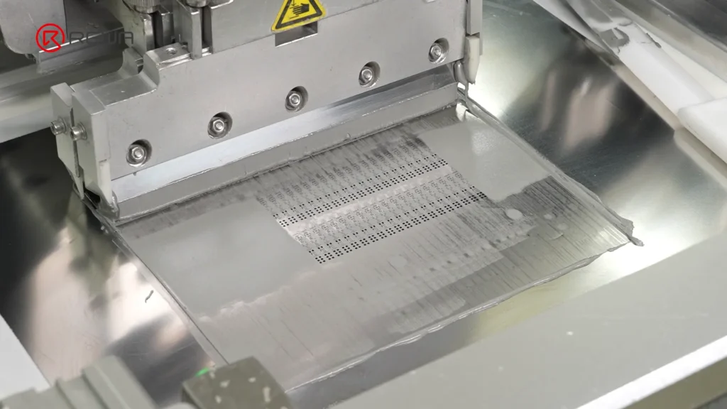
    Automated SMT squeegee applying gray solder paste over a stencil onto a BMS circuit board

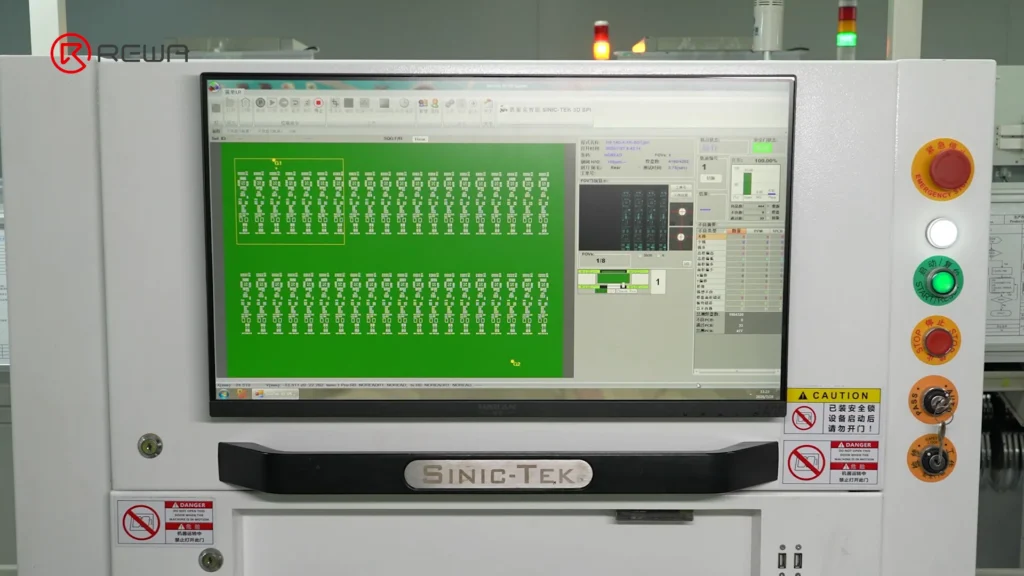
    Infrared marking helps identify the positions of the solder pads, while an SPI system checks the printed solder paste to identify issues such as:

    • Solder paste offset
    • Insufficient solder paste
    • Excessive solder paste
    • Solder bridging
    A Sinic-Tek 3D SPI machine monitor displaying a panel inspection layout for solder paste quality control

    This inspection is important because inaccurate solder paste printing can affect the quality of component soldering later in the process.

    Step 2: High-Speed Component Placement

    After solder paste printing, SMT machines precisely place resistors, capacitors, inductors, and other components onto their designated positions on the PCB.

    High-speed nozzles pick up individual components and place them according to the programmed layout of the PCB. Infrared reference marks help the equipment maintain accurate positioning.
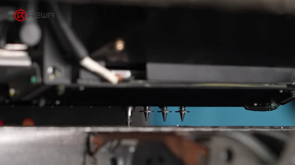
    Automated SMT pick-and-place nozzles positioned above a circuit board

    For battery BMS boards, precise component placement is essential because the board contains many small components within a compact design.

    Step 3: Installing the TI Battery Management Chip

    One of the key components on the board is the TI chip. As a key control component of the battery management system, it serves as the “brain” of the BMS, helping monitor and manage battery performance.
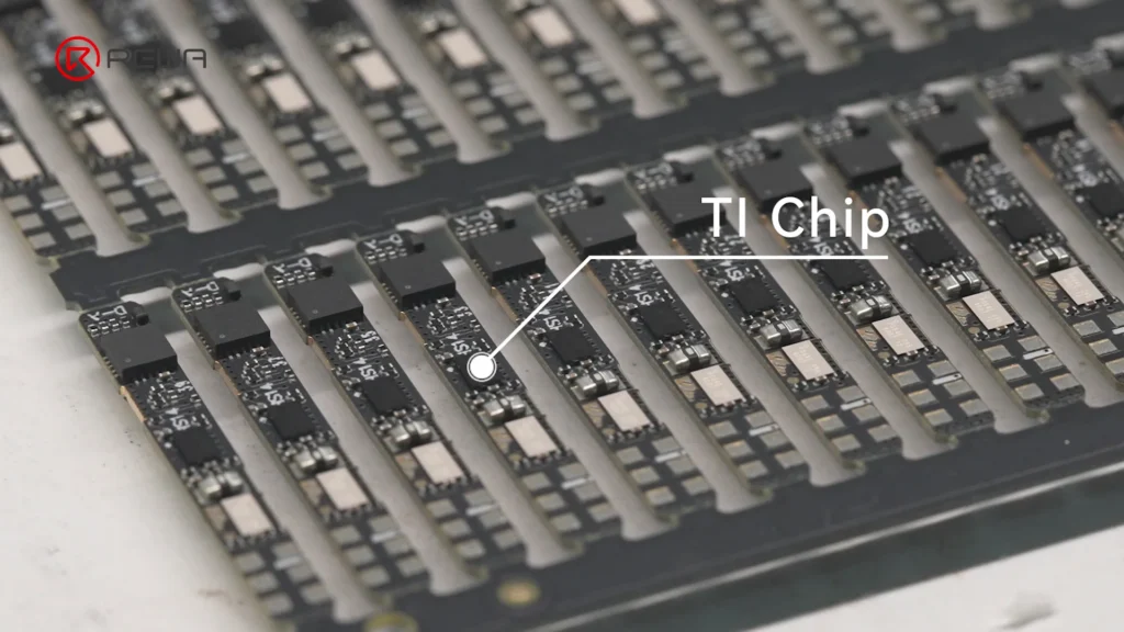
    Array of BMS circuit boards with a callout label pointing to the installed TI chip

    Il Batteria selezionata REWA board uses a custom TI chip with an Impedance Track algorithm.

    In poche parole:

    The algorithm helps the battery system estimate the battery’s remaining capacity more accurately by tracking the battery’s electrical characteristics, including impedance.

    Battery impedance changes as the battery operates and ages. Monitoring these characteristics allows the battery management system to make more informed estimates of the battery’s actual state.

    Step 4: Reflow Soldering and AOI Inspection

    Once the components have been placed, the PCB enters the reflow soldering process. The board passes through a controlled thermal profile consisting of preheat, soak, reflow, and cooling stages, permanently connecting the components to the PCB.

    Afterward, the board undergoes AOI (Automated Optical Inspection) scanning.

    Simply put:

    AOI uses cameras to inspect the board automatically and compare the soldered components and joints against predefined standards or a golden sample.
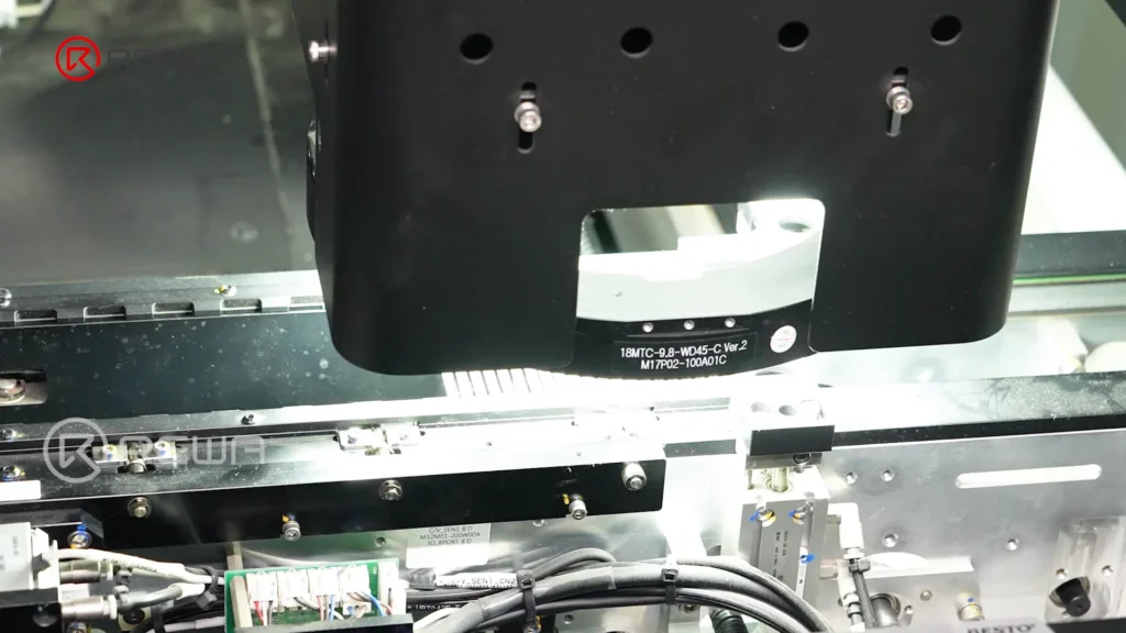
    Automated optical inspection machine head scanning circuit boards under bright light on an assembly line

    If the system identifies an NG (No Good) board, the board is manually reviewed to separate real defects from false positives.

    Step 5: Underfill Reinforces BGA Component Connections

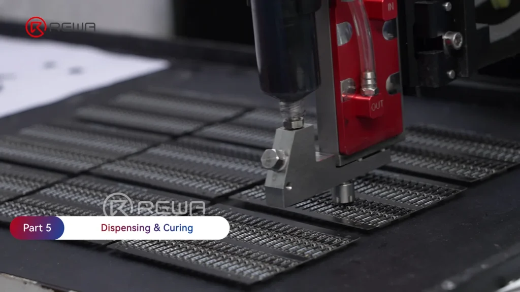
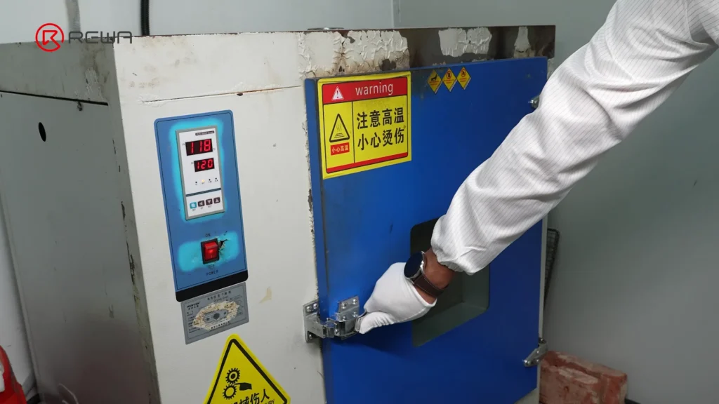
    After solder inspection, automated equipment applies underfill along the edges of BGA components before the adhesive is cured in an oven, which helps provide additional mechanical support.

    For battery BMS boards, this stage can improve resistance to physical shock and vibration, helping strengthen the connection between the component and PCB during handling and use.
    How iPhone Aftermarket Battery BMS Boards Are Made
    A gloved worker closing the door of an industrial drying oven used to cure underfill adhesive

    Step 6: Firmware Programming and Flex Cable Bonding

    The completed PCB is programmed with firmware before its flex cable is bonded using controlled heat and pressure. To put it simply, firmware is the embedded software that controls how the hardware operates.

    How do the controlled heat and pressure achieve?

    Through a hot-bar bonding process, the controlled heat and pressure are used to bond the flex cable to the PCB.
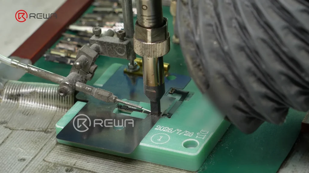
    bonding flex cable

    After bonding, the flex cable connection is verified through FCT (Functional Circuit Test) to check whether the assembled board actually functions as intended.

    Step 7: Battery Cell and BMS Board Assembly

    In the assembly stage, the factory first uses capacity-matched cells. The cell tabs are then cut before the cell is connected to the BMS board through fiber laser spot welding.

    Why Is Weld Quality Important?

    The weld connects the battery cell to the BMS board, so the quality of this connection directly affects the electrical and mechanical integrity of the battery pack.
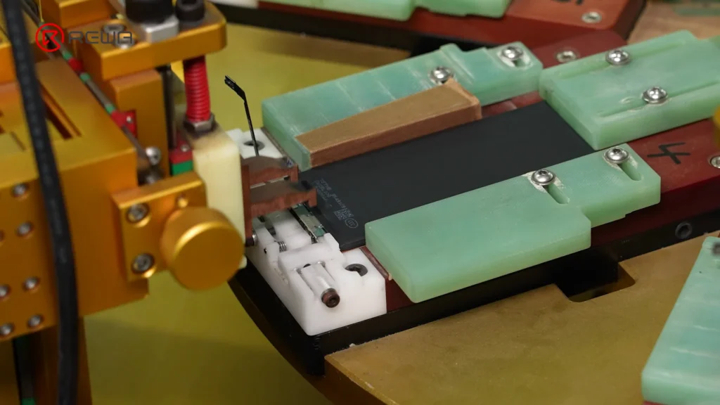
    Automated spot welding equipment connecting a battery cell to a BMS board held in an assembly fixture

    After welding, each weld joint is checked for durability. The battery pack then receives insulation tape and a rubber casing as part of the assembly process, helping provide both electrical insulation and physical protection.

    Step 8: Final Quality Inspection and Battery Testing

    Manufacturing does not end when the battery pack is assembled. A strict final quality inspection is performed before the battery is considered ready for shipment.

    After final inspection, the battery enters a resting period, during which parameters such as voltage and internal resistance are monitored.
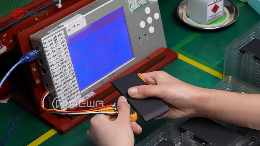
    Technician connecting an assembled iPhone battery to a digital testing device to monitor voltage and internal resistance

    Monitoring voltage and internal resistance during the resting period provides additional data for quality control.

    Why the BMS Board Matters for Aftermarket iPhone Batteries

    The BMS board is often hidden inside the battery, so it is easy to overlook when comparing aftermarket batteries. However, its design and manufacturing quality can influence important aspects of battery operation.

    A reliable third-party battery requires more than simply selecting a battery cell with the right capacity. The cell, BMS board, firmware, electrical connections, protection circuitry, manufacturing process and strict quality test before shipping all work together.
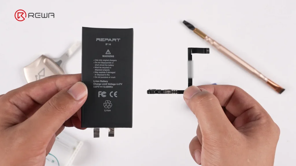
    Hands holding a black iPhone 14 battery cell on the left and a small BMS board with flex cable on the right

    For distributors, refurbishing facilities, and repair shops, this means that battery evaluation should go beyond looking at the printed capacity or external appearance.

    Domande frequenti

    What is the difference between a battery cell and a BMS board?

    The battery cell is the component that stores electrical energy. The BMS board is the electronic management and protection system that monitors the cell and controls related battery functions.

    What is a TI chip in a battery BMS board?

    TI refers to Texas Instruments, a semiconductor manufacturer whose battery-management ICs are used in various battery applications. In the REWA Selected battery board shown in the video, a custom TI chip with an Impedance Track algorithm is used to support accurate battery monitoring and gauge estimation.

    Why are SPI and AOI inspections important?

    SPI checks the accuracy of solder paste printing before components are soldered, while AOI uses cameras to inspect the assembled PCB and solder joints afterward. These inspections help identify manufacturing issues at different stages of PCB production.

    Why does REWA test battery voltage and internal resistance after assembly?

    Voltage and internal resistance provide important information about the electrical condition of a battery pack. Monitoring these parameters after assembly and during the resting period adds another layer of quality control before the battery is shipped.

    Why measure internal resistance during final quality inspection?

    Internal resistance is one of the important electrical characteristics of a battery. Lower internal resistance generally means less electrical energy is lost inside the battery when current flows, although battery performance cannot be judged by this parameter alone.

    Conclusione:

    An aftermarket iPhone battery is more than a battery cell. Behind the finished product is a BMS board that integrates electronic components, battery-management technology, protection functions, firmware, and flex-cable connections.

    From a bare PCB to a complete battery pack, every stage can contribute to the consistency and reliability of the finished battery.

    By combining rigorous quality control process with technical support, REWA Technology is committed to developing high-standard aftermarket battery solutions for professional repair businesses worldwide. If you have any question, please feel free to contattateci.
  • Riparare i pad di saldatura rotti con il capocorda a saldare

    Riparare i pad di saldatura rotti con il capocorda a saldare

    Il capocorda di saldatura REFOX può essere posizionato direttamente sulle piazzole mancanti, in modo efficiente e conveniente con una saldatura stabile.

  • Mastering Desoldering & Soldering of iPhone X PMU

    Mastering Desoldering & Soldering of iPhone X PMU

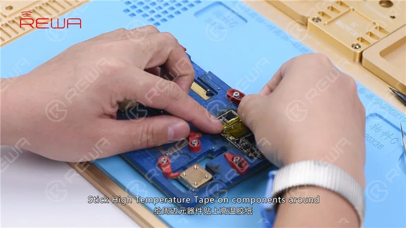
    Today’s handwork course will focus on a tutorial for desoldering and soldering the iPhone X PMU. Begin by attaching the upper layer of the motherboard to the PCB Holder, then proceed to apply High-temperature Tape on the surrounding components.

    mastering desoldering soldering iphone pmu h023 sol

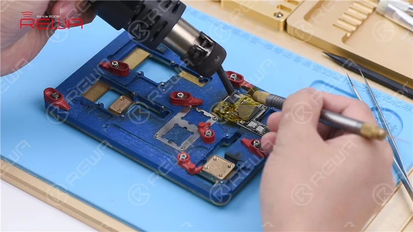
    Start by removing the black adhesive surrounding the PMU. Apply heat using a Hot Air Gun set at 280℃ with an air flow of 3. Then, use a specialized knife to get rid of the black adhesive around the chip.

    mastering desoldering soldering iphone pmu h023 sol 2

    Attenzione: When removing the black adhesive near the PMU to prevent dislodging any nearby components.

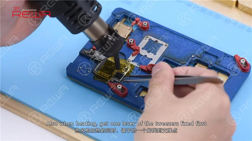
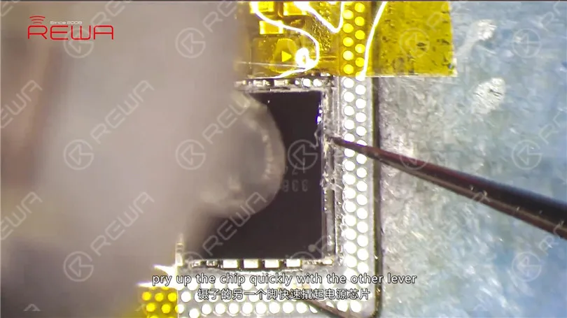
    Apply heat to the PMU using a Hot Air Gun set at 330℃ with an air flow of 5. Prior to heating, secure one end of the tweezers. After 15 seconds, when the solder begins to melt, swiftly lift the chip using the other end of the tweezers. Ensure that you lift the chip at the appropriate moment to avoid causing damage to the bonding pad.

    mastering desoldering soldering iphone pmu h023 sol 3
    mastering desoldering soldering iphone pmu h023 sol 4

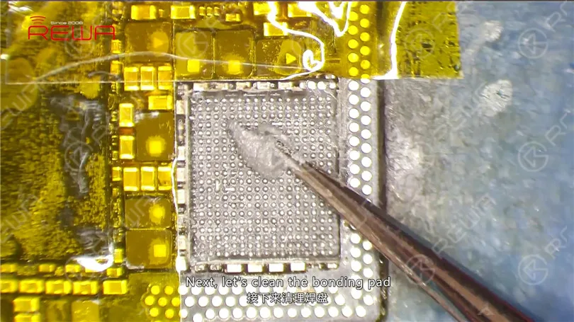
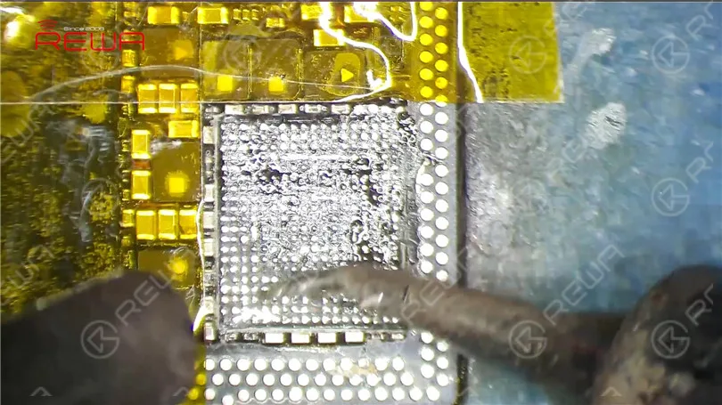
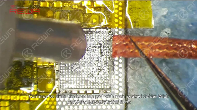
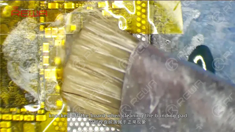
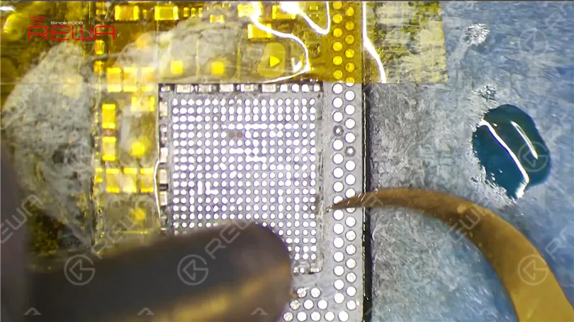
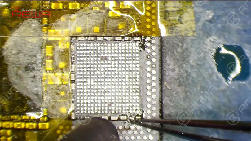
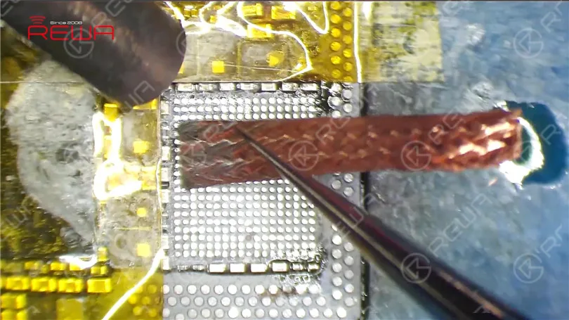
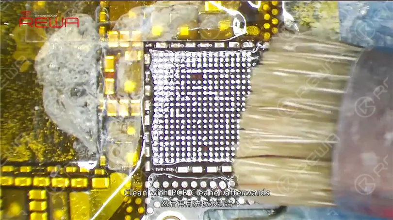
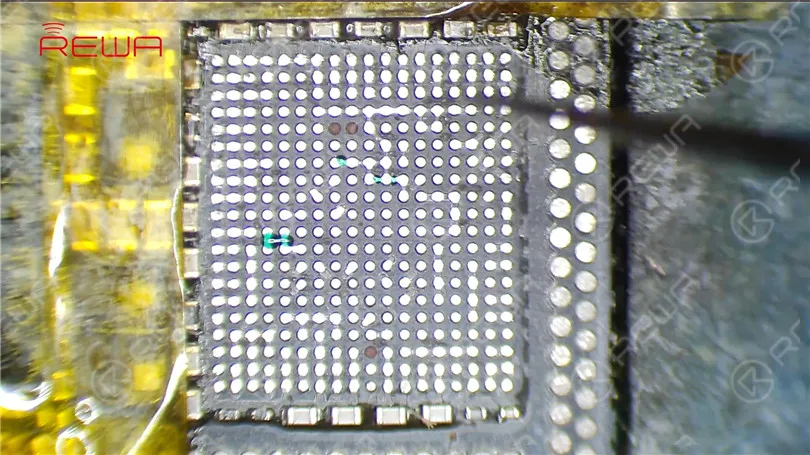
    Next, let’s clean the bonding pad. Apply some mid-temperature Solder Paste to the bonding pad. Heat with Hot Air Gun at 280℃. Meantime, clean the bonding pad with Soldering Iron at 360℃. Continue to clean the bonding pad with rosin soaked Solder Wick. Clean with PCB Cleaner afterwards. Tips: bonding pads of those empty pins might get knocked off the board when cleaning the bonding pad, which is normal. We can just leave them alone.

    desoldering&soldering of iPhone X PMU
    mastering desoldering soldering iphone pmu h023 sol 6
    mastering desoldering soldering iphone pmu h023 sol 7
    mastering desoldering soldering iphone pmu h023 sol 8

    Continue to remove black adhesive on/around the bonding pad. Also when we pry up the chip, components around get knocked off the board. So our next move is to re-solder these components. First, apply some Paste Flux to their bonding pads. Then, apply solders with Soldering Iron. Get these components in position. And then solder with Hot Air Gun at 330℃, air flow 3.

    mastering desoldering soldering iphone pmu h023 sol 9
    mastering desoldering soldering iphone pmu h023 sol 10

    Before soldering the chip, clean the bonding pad again. Clean with PCB Cleaner afterwards.

    mastering desoldering soldering iphone pmu h023 sol 11
    mastering desoldering soldering iphone pmu h023 sol 12

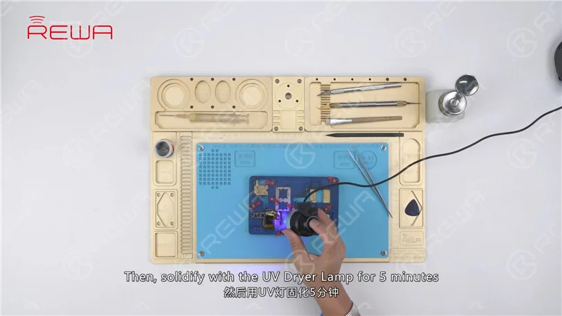
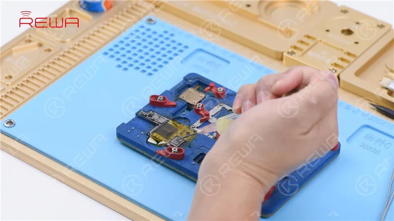
    Also when we remove the black adhesive, some of the insulation varnish on PCB has fallen off the board. So we need to remedy with the UV Curable Solder Mask. Dip some UV Curable Solder Mask with tweezers. And apply the solder mask to the exposed area. Then, solidify with the UV Dryer Lamp for 5 minutes.

    mastering desoldering soldering iphone pmu content 9ff202ff81dc
    mastering desoldering soldering iphone pmu h023 sol 13

    Now we can solder the PMU. Apply some Paste Flux to the bonding pad. Get a new PMU in position. Make sure you put it in the right direction. Solder with Hot Air Gun at 330℃, air flow 3 for 20s.

    mastering desoldering soldering iphone pmu h023 sol 14

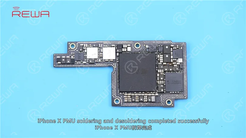
    With the chip sinking and Paste Flux flowing, continue heating for 10s. Wait for the upper layer to cool for 5 minutes. Tear off the High Temperature Tape. Clean with PCB Cleaner afterwards. iPhone X PMU soldering and desoldering completed successfully.

    mastering desoldering soldering iphone pmu h023 sol 15
  • Consigli per la saldatura e dissaldatura manuale del connettore di iPhone X | Corso Online REWA Academy

    Consigli per la saldatura e dissaldatura manuale del connettore di iPhone X | Corso Online REWA Academy

    Oggi, il corso aperto di REWA Academy condividerà alcune tecniche manuali sulla riparazione della scheda madre dell'iPhone. Prendendo come esempio la dissaldatura e la saldatura del connettore FPC Wi-Fi e del connettore del touch della serie iPhone X e combinandole con alcuni errori che i tecnici di riparazione alle prime armi potrebbero commettere, condivideremo anche suggerimenti più diretti ed efficienti.

  • Efficient Soldering/Desoldering Tool for iPhone X/XS/XS Max

    Efficient Soldering/Desoldering Tool for iPhone X/XS/XS Max

    The iPhone XS, with its stunning design and powerful features, has become a sensation among young tech enthusiasts. However, its intricate motherboard, comprising thousands of neatly soldered components in a compact space, presents a unique challenge for repair experts. This article introduces a game-changing solution that can make iPhone X/XS/XS Max motherboard repair a breeze, ensuring professional repairs with ease and precision.

    The Challenge of iPhone XS Logic Board Repair

    The iPhone XS logic board is a marvel of engineering, designed as a double-stacked board soldered together with the help of a third-spaced PCB. Repairing it requires separating these two layers, a task that, until recently, was quite daunting. Traditional repair methods involve using a hot air gun to heat the upper and lower logic board, a process that can be challenging to control. Excessive heat can damage the motherboard, leading to hidden problems.

    Introducing the iPhone Motherboard Soldering/Desoldering Rework Station

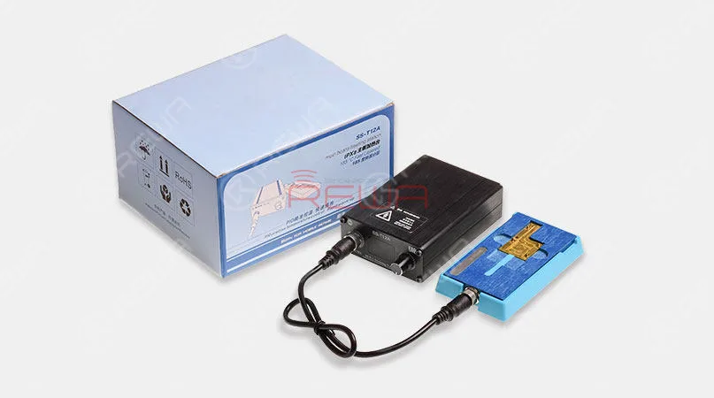
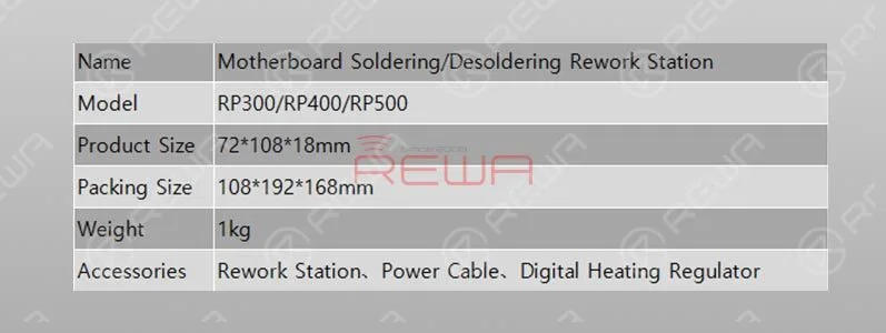
    To overcome these challenges, REWA has developed an innovative solution – the iPhone Motherboard Soldering/Desoldering Rework Station. This tool offers a range of features that simplify and streamline the repair process:

    Desoldering Tool for iPhone X/XS/XS Max

    Special Features:

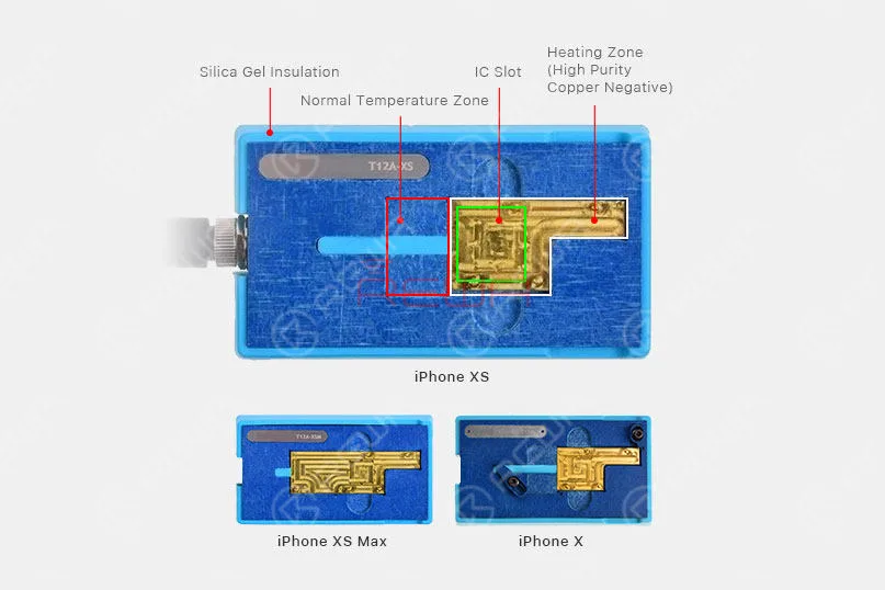
    • Silica Gel Insulation: Provides optimal insulation to safeguard sensitive components.
    • Precise Temperature Control: Ensures the right amount of heat for successful repairs.
    • Fast Heating-up: Save time with quick, efficient heating.
    • LED Digital Display: Provides real-time temperature monitoring.
    • Threaded coupling: Ensures secure and stable connections.
    • Partial Heating: Allows precise targeting of components.
    Desoldering Tool for iPhone X/XS/XS Max

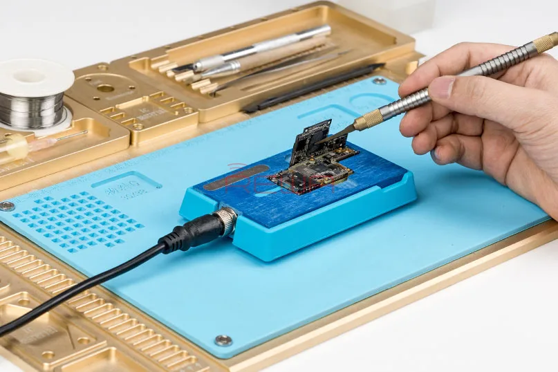
    How to Use the Rework Station

    Repairing an iPhone X/XS/XS Max logic board is now a straightforward process with the Rework Station. Here are three simple steps to achieve success:

    Fase 1: Place the motherboard on the specialized Rework Station.

    Gently position the logic board on the station, ensuring it’s secure and ready for repair.

    Fase 2: Wait for 1 minute after adjusting the heating temperature.

    Use the precise temperature control to set the desired heat level. After making the adjustment, wait for a minute to allow the station to reach the optimal temperature.

    Fase 3: Motherboard soldering/desoldering completed.

    With the station ready, the motherboard can be efficiently repaired, ensuring a successful outcome without the risk of overheating.

    Product Details

    Desoldering Tool for iPhone X/XS/XS Max

    Witness the Magic in Action

    To see the Rework Station in action, we’ve prepared a special video showcasing the iPhone XS motherboard repair process using this incredible tool. Check it out now for a first-hand look at how this technology can transform your repair process and ensure professional results.

    Conclusione:

    By incorporating the iPhone Motherboard Soldering/Desoldering Rework Station into your repair toolkit, you’ll not only save time but also elevate the quality of your repairs.