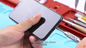
iPhone won’t turn on and the screen is black or frozen? After software issue being excluded, the problem may be caused by a faulty logic board. Since logic board of iPhone X is a single one that’s basically been folded over and soldered together, the unique design and structure have made any repairs to the logic board far more difficult than previous series. With our iPhone X won’t power on repair case today, the fault has been confirmed as inductor damage by voltage measurement. And we can fix the iPhone X won’t turn on issue by inductor replacing and board re-soldering. Let’s check out the video to see how to fix iPhone X black screen issue.
Tag: iPhone
-
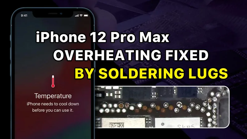
How to Fix iPhone 12 Pro Max Overheating Issue with Soldering Lugs
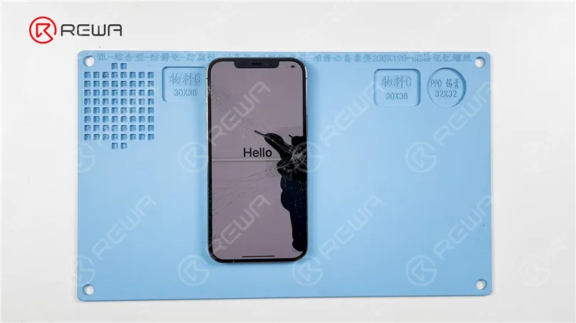
Today we will share how to fix iPhone 12 Pro Max overheating or temperature warning issue. The phone has been dropped before and the screen is cracked. After boot-up, the phone shows a temperature warning.
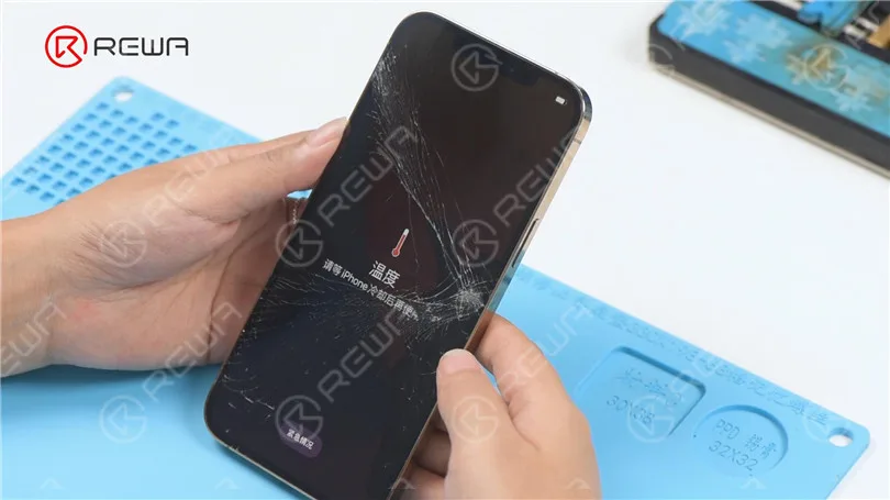
Next, we take apart the phone for testing. Disconnect the flex cables. Remove the motherboard. In the first place, we check if the motherboard is deformed. The motherboard is not deformed.
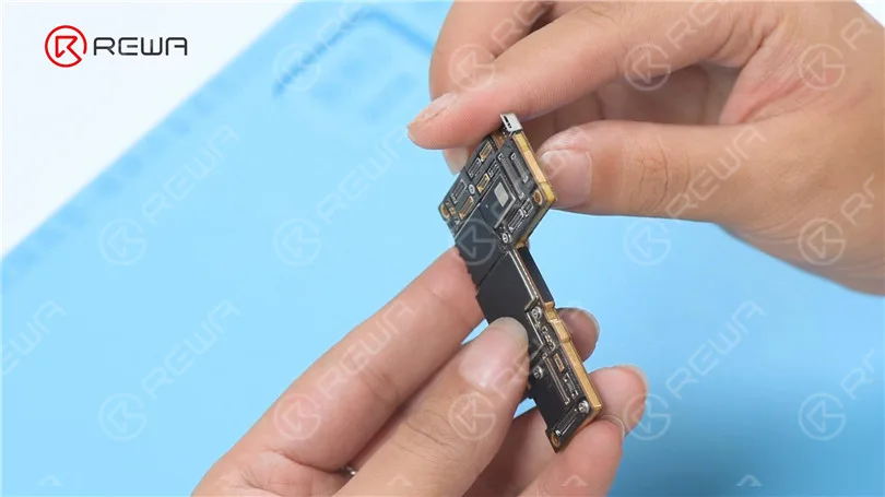
It can be seen under the microscope that the motherboard has pseudo-soldering. Then we need to separate the motherboard.
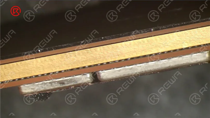
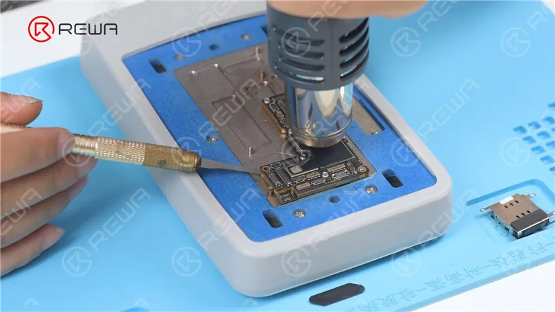
Detach the foam and plastic part. Put the motherboard on the 165 °C Piattaforma di riscaldamento to heat. Since the middle layer of iPhone 12 lineup adopts middle-temperature solder paste for soldering, we need to assist the heating with a Hot Air Gun at 330 °C. Try to pry up the logic board with a Pry Blade while heating. If the logic board becomes loose, remove it. Then remove the signal board.
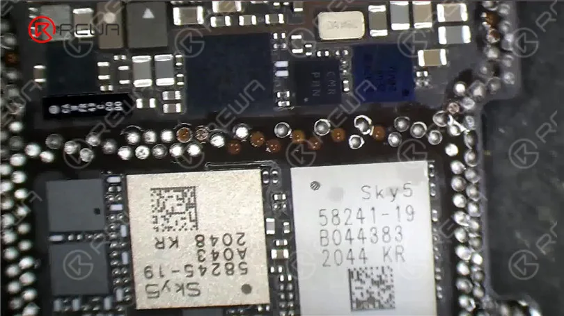
It can be seen under the microscope that pads on the logic board are missing. Then we need to repair the bonding pads. Clean the bonding pads with Saldatore at 380 °C and Solder Wick. Next, clean the bonding pads with PCB Cleaner.
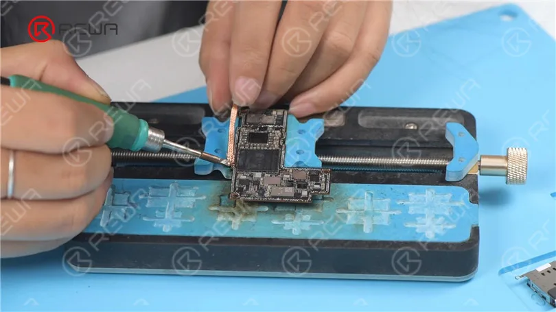
Then scrape the missing pads to show the circuits with a Sculpture Knife. Please pay attention not to damage the GND while scraping.
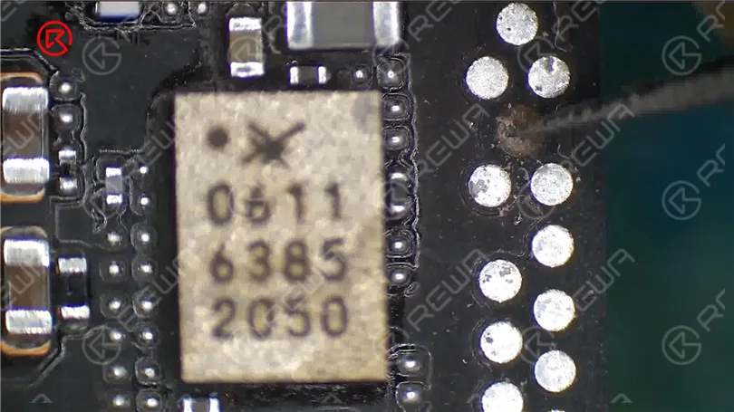
Clean the bonding pads with PCB Cleaner. Apply tin to the bonding pads with a Soldering Iron.
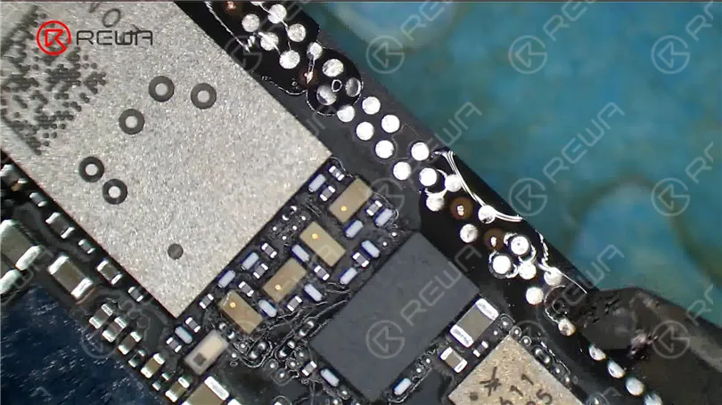
Then we put the Soldering Lugs in position. Apply some Paste Flux. Heat with a Soldering Iron to solder. Clean the bonding pads with PCB Cleaner.
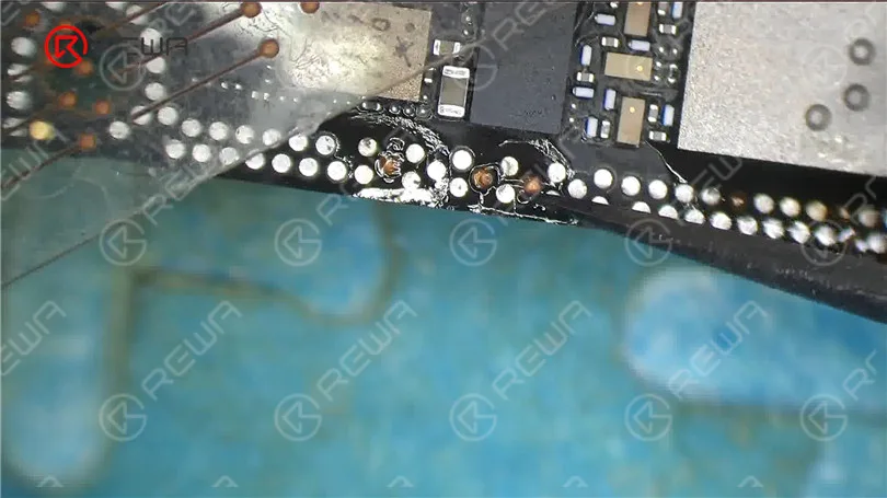
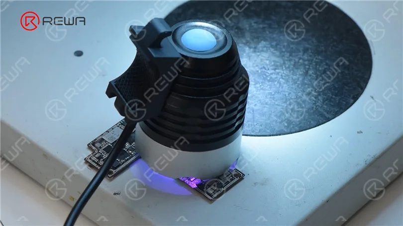
Apply some Solder Mask to the bonding pads. Then solidify with a UV Lamp. After solidifying, remove excess solder mask with a Sculpture Knife to show the pads.
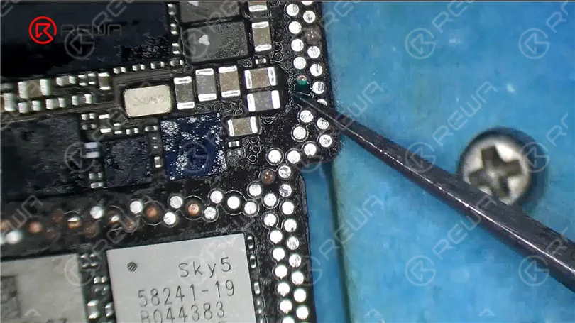
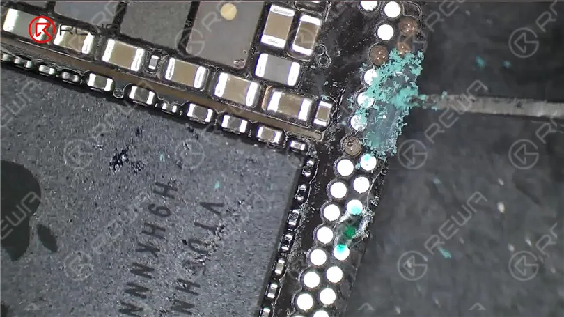
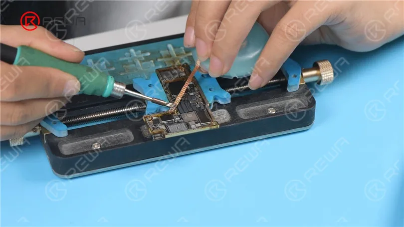
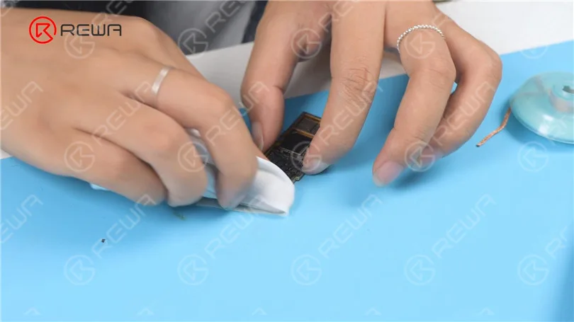
Clean the bonding pads with PCB Cleaner. Then clean the bonding pads with Soldering Iron and Solder Wick. Keep cleaning the bonding pads with a Dust-free Wipe.
Next, we reball the signal board. Attach the signal board to the holder. Put the reballing stencil in position. Apply some low-temperature Solder Paste evenly. Remove excess solder paste.
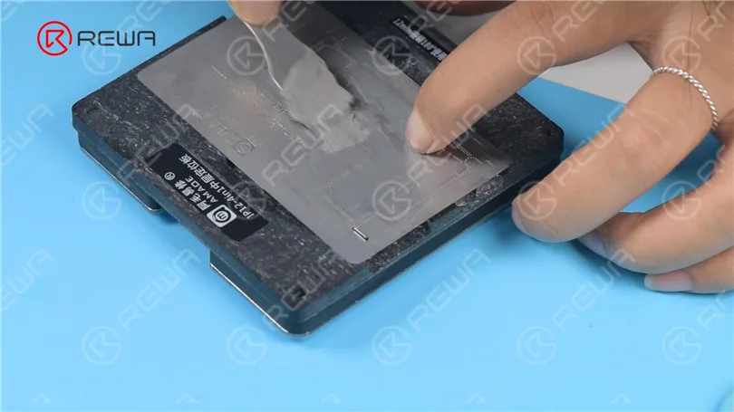
Detach the reballing stencil. Put the motherboard on the 165 °C Heating Platform to heat for recombination. Remove the motherboard after it has cooled for 5 minutes.
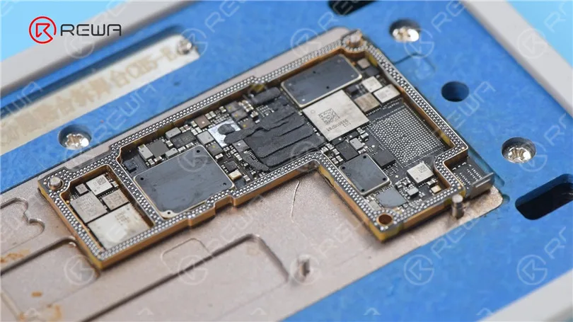
Install the motherboard for testing. Connect the screen. The phone turns on normally. The temperature warning has disappeared.
-
L'iPhone 11 Pro non si accende - Guida professionale alla riparazione
Ciao a tutti! Il nostro corso oggi riguarderà la riparazione di un iPhone 11 Pro che non si accende.
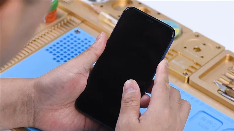
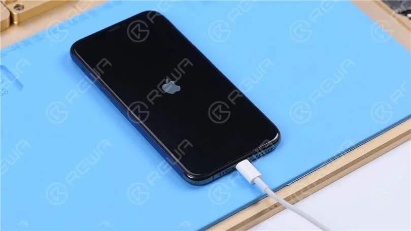
Premi il pulsante di accensione. Il telefono non si accende.
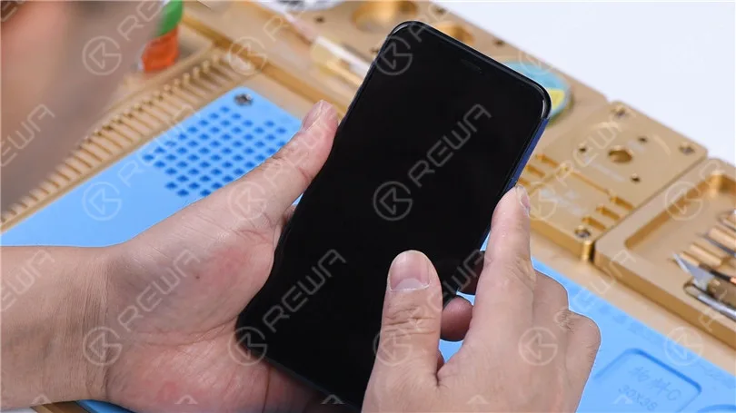
Smonta e prova
Poi smontiamo il telefono e testiamo.
Rimuovere le due viti pentalobe sul bordo inferiore.
Tira la piccola sporgenza sulla ventosa per sollevare lo schermo.
Inserisci una graffa quando c'è uno spazio e falla scorrere lungo lo spazio.
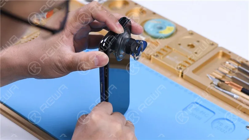
Dopo aver sollevato lo schermo, rimuovere i coperchi di protezione.
Scollega la batteria e rimuovi lo schermo. Collega la scheda madre con il cavo di alimentazione.
L'amperometro mostra una corrente elevata di 3,1A.
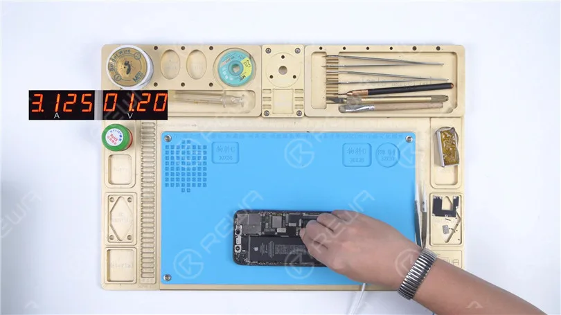
Scollegare i cavi flessibili. Rimuovere il vassoio della scheda SIM.
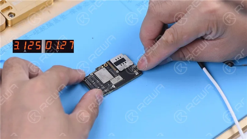
Scollegare la scheda madre. Ricollegare la scheda madre con il cavo di alimentazione.
L'amperometro mostra ancora una corrente elevata di 3,1 A.
Indica che la corrente elevata non ha nulla a che fare con altri cavi flessibili.
Il guasto è sulla scheda madre.
Misurazione in modalità diodo
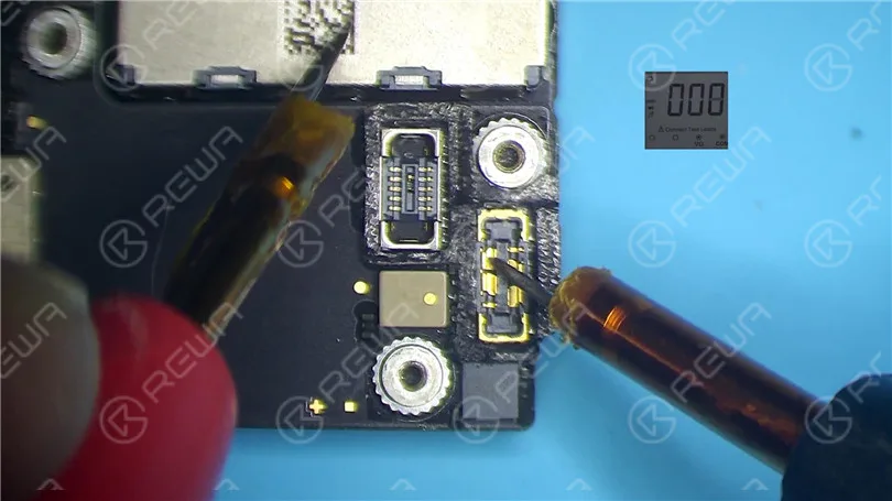
Esegui misurazione in modalità diodo del pin 1 del J7010 del connettore della batteria.
Il valore del diodo è 0. Indica che il circuito di alimentazione principale è in corto con la massa.
Poiché il circuito fornisce contemporaneamente alimentazione alla logic board e alla signal board, dobbiamo separare la motherboard per localizzare il guasto.
Separazione della scheda madre
Rimuovere la schiuma sulla scheda madre.
Scalda il retro della scheda madre con una pistola ad aria calda a 240 gradi Celsius.
Rimuovere la carta protettiva.
Metti la scheda madre su Piattaforma di riscaldamento.
Per facilitare la rimozione della scheda logica dopo la separazione, avvitare una vite sulla scheda logica.
Imposta la temperatura della piastra riscaldante a 185 gradi Celsius.
Bloccare la vite per rimuovere la scheda logica quando la temperatura è salita a 185 gradi Celsius. Rimuovere la scheda del segnale.
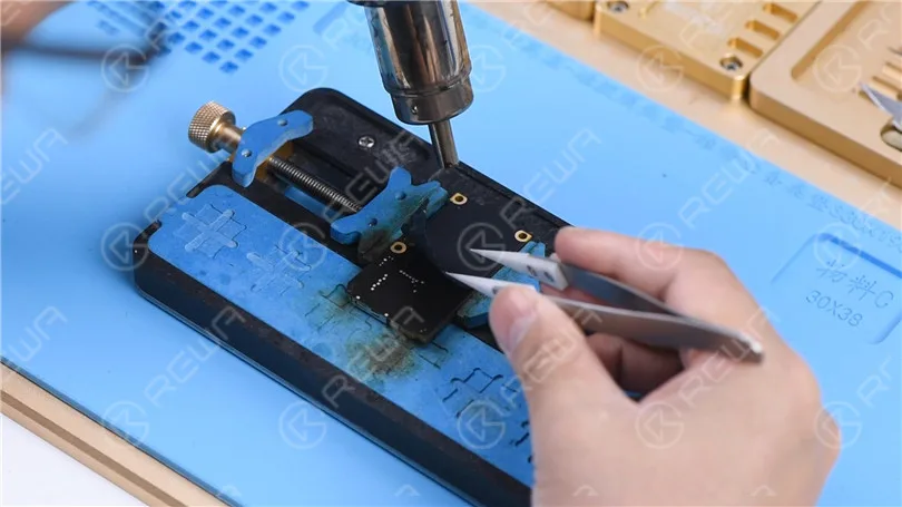
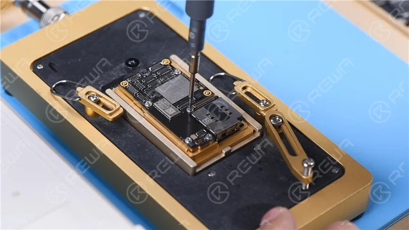
Misurazione in modalità diodo
Esegui la misurazione in modalità diodo del pin 286 sulla scheda del segnale. Il valore del diodo è 0.
Indica che l'alimentazione principale della scheda del segnale è in corto verso massa.
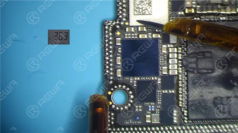
Misura il pin 286 sulla scheda logica.
Il valore del diodo è 363, il che significa che la logic board è normale.
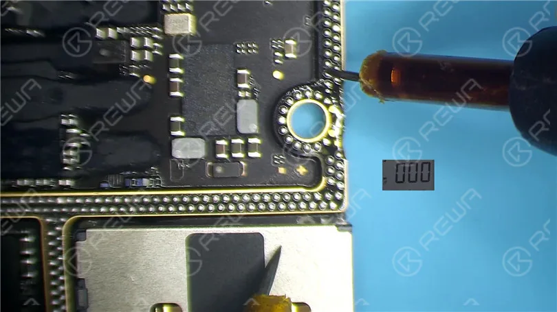
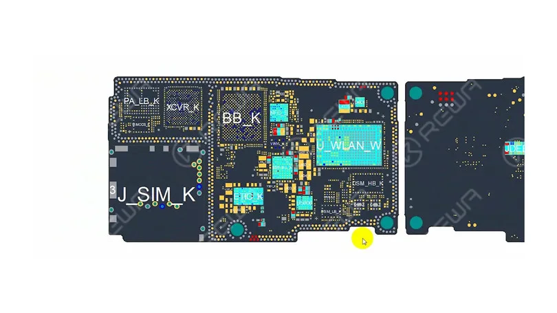
Apri la bitmap. Possiamo vedere che ci sono molti componenti associati sul circuito dell'alimentatore principale.
Rilevamento della pece greca
Successivamente, dobbiamo individuare il componente difettoso con il rilevamento di colofonia.
Rimuovere la pasta termica con un bisturi da scultore.
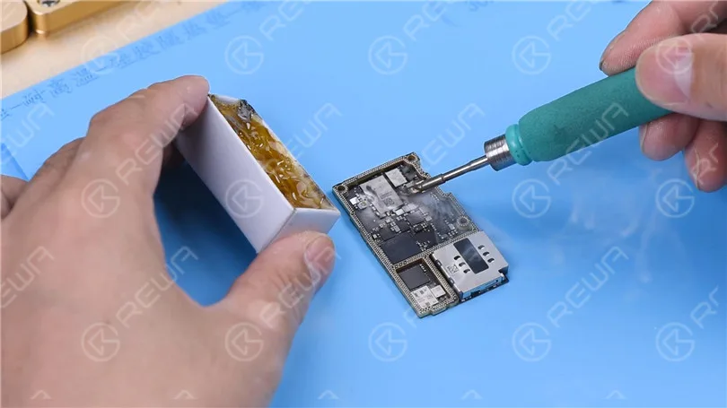
Saldare il flussante con un saldatore a 365 gradi Celsius.
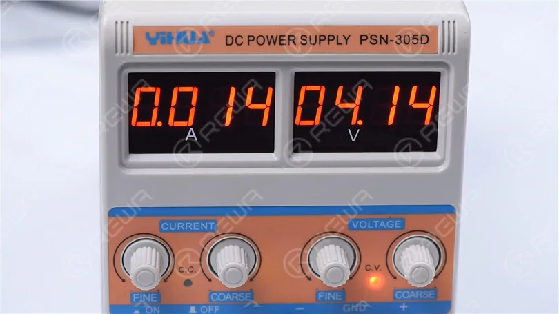
Fumo resina sulla scheda di segnalazione. Impostare l'alimentazione in corrente continua a 4,1V.
Collega l'anodo positivo e negativo dell'alimentazione a corrente continua con le sonde del multimetro.
Collega la sonda nera a massa.
Collega la sonda rossa al pin 286 sulla scheda del segnale.
Si può vedere la colofonia sul condensatore C1200 K che si è fusa. Ciò indica che il condensatore è danneggiato.
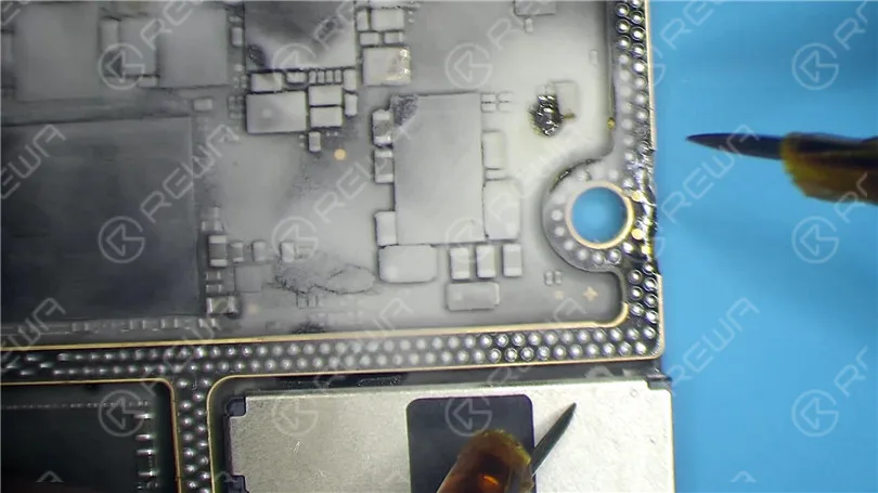
Poi scaldiamo con la pistola ad aria calda a 350 gradi Celsius. Rimuovere il condensatore con una pinzetta.
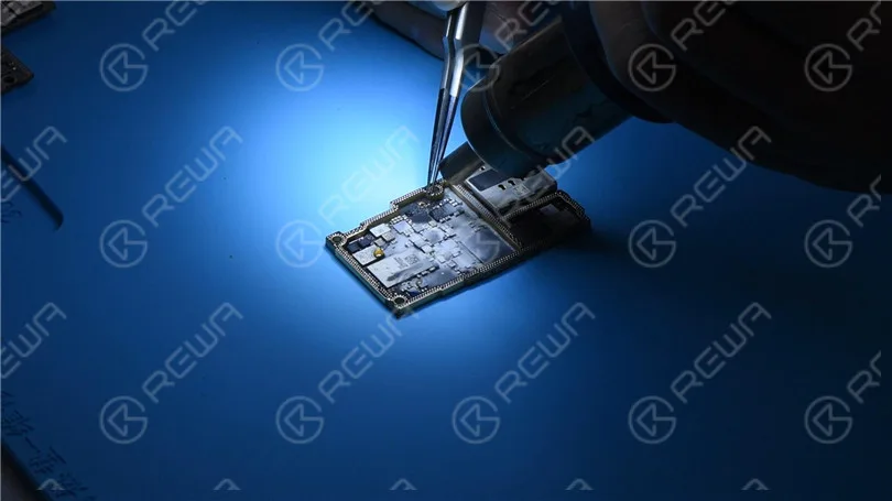
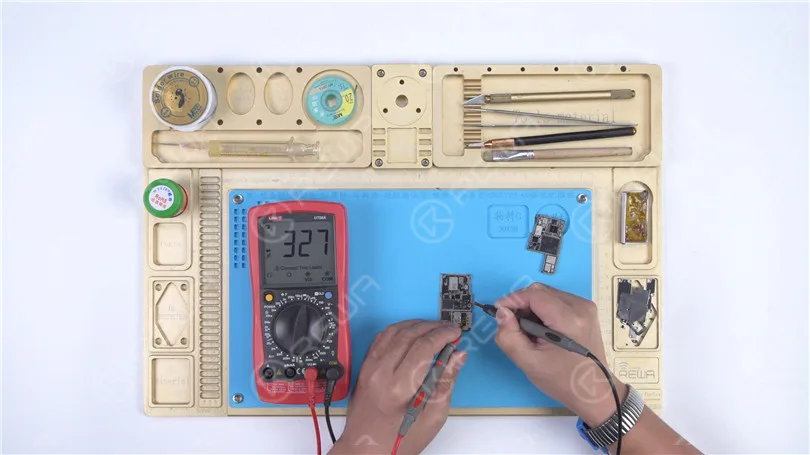
Pulisci la colofonia sulla scheda del segnale con il pulitore per PCB. Esegui una seconda misurazione in modalità diodo. Il valore del diodo ritorna a un valore normale di 327.
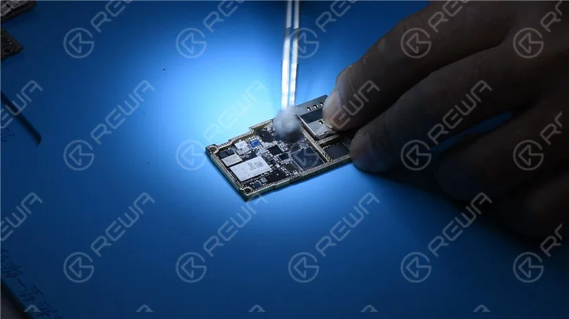
Ricombinazione della scheda madre
Spalmare la pece con un saldatore e della treccia dissaldante a 365 gradi Celsius per rimuovere lo stagno sul pad di saldatura.
Pulisci la scheda del segnale con un pulitore per PCB. Rimuovi lo stagno e pulisci la scheda logica con lo stesso metodo.
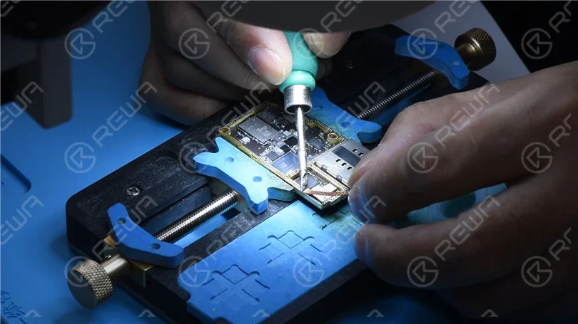
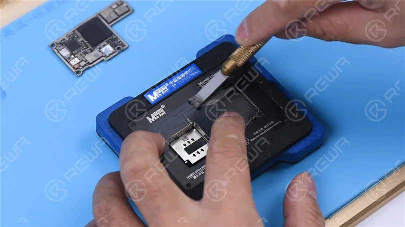
Attaccare la scheda di segnale alla Piattaforma di Reballing.
Posizionare la maschera di reballing. Per evitare che la pasta saldante fluisca nelle fessure della scheda madre, inserire una piastra metallica.
Applicare uno strato di pasta saldante a bassa temperatura.
Rimuovere la maschera di reballing.
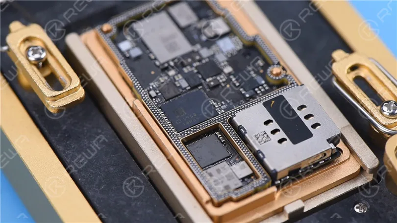
Posizionare il pannello del segnale sulla piattaforma di riscaldamento a 185 gradi Celsius per riscaldare.
Dopo che le sfere di saldatura si sono formate, spegni l'alimentazione e raffredda la scheda madre per 5 minuti.
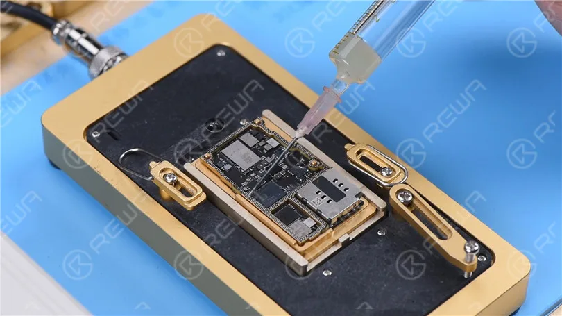
Applica un po' di pasta flussante.
Allineare la scheda logica con la scheda dei segnali.
Mantenere il riscaldamento sulla piastra riscaldante a 185 gradi Celsius.
Quando la temperatura raggiunge i 185 gradi Celsius, continuare a scaldare per 1 minuto.
Questo passaggio serve a garantire che la scheda logica e la scheda del segnale si adattino perfettamente.
Test
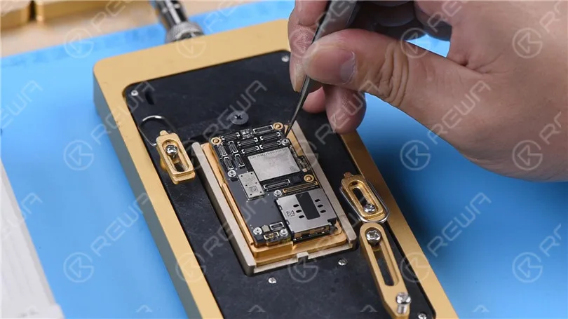
Collega la scheda madre con il cavo di alimentazione.
Cortocircuito a massa del pin 12 della J7700. La corrente di avvio diventa normale.
Metti la scheda madre sul telefono.
Collega i cavi flessibili. Collega lo schermo e la batteria.
Perché la batteria è scarica. Collega il cavo di ricarica e il telefono si accende normalmente.
-
Riparare iPhone X No Service saldando un filo
L'iPhone X non ha banda base, nessun numero IMEI e nessun servizio. Guarda questo video per vedere come risolviamo il problema realizzando ponticelli.
-
Come riparare il pulsante Home di iPhone 7 che non funziona dopo un danno d'acqua
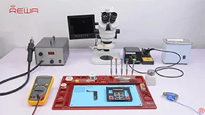
Water damage is a common issue for iPhone in daily use. In this video, the home button of iPhone 7 is not working after water damaged, because lines on logic board get corroded and damaged. Since there is a high failure risk in repairing, REWA LAB presents you a method to fix heavily corroded and damaged logic board step by step by Ultrasonic Cleaner and making jumper wire. To fix your iPhone 7 home button issue caused by water damage, please follow the repair operations of our tutorial video.
-
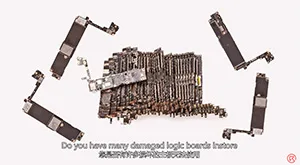
Servizio di riparazione della scheda logica di iPhone/iPad/MacBook REWA
Non avete idee per le vostre schede logiche difettose? Non sapete come gestire le riparazioni più difficili? Perché non rivolgersi a REWA? Offriamo servizi di riparazione di schede logiche a livello di chip per iPhone, iPad e MacBook. Esperti e tecniche professionali possono liberarvi da riparazioni pesanti e difficili. Con soli 5 passaggi, possiamo risolvere quasi tutti i problemi di riparazione della scheda madre di iPhone, iPad e MacBook. Guardate il video per i dettagli.
-
Riparazione del touch screen dell'iPhone X non reattivo
Il nostro corso di oggi riguarda la riparazione del touchscreen dell'iPhone X che non risponde.
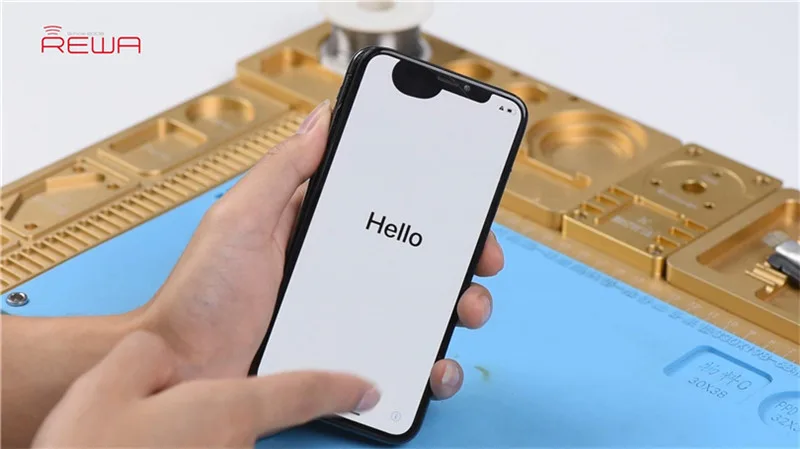
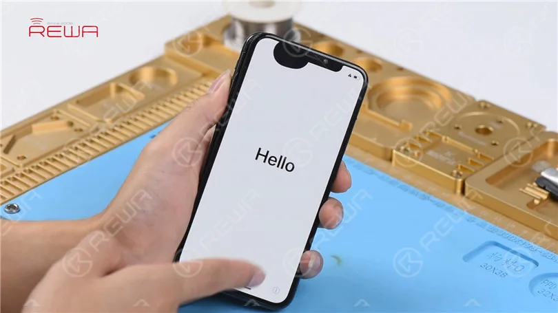
Premere il pulsante di accensione per accendere il telefono. Il telefono si accende normalmente. Il touch screen del telefono non risponde.
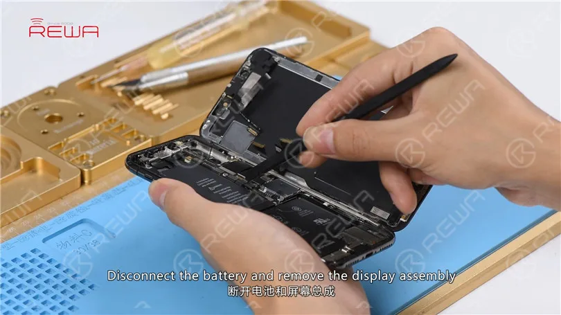
Spegnere il telefono e smontarlo. Scollegare la batteria e rimuovere il display.
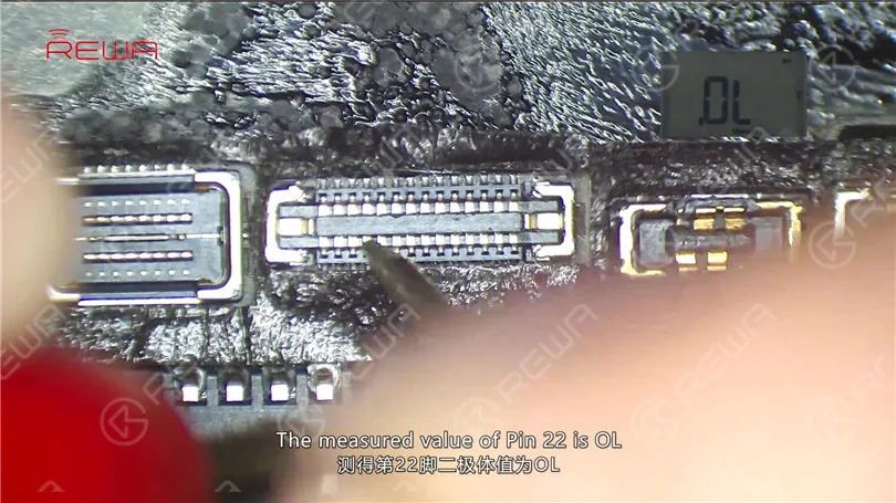
Estrarre la scheda madre. La prima cosa da fare è controllare il connettore FPC del Touch ID J5800. Eseguire la misurazione in modalità diodo di J5800. Il valore misurato del pin 22 è OL, il che indica che il circuito del pin 22 è aperto.
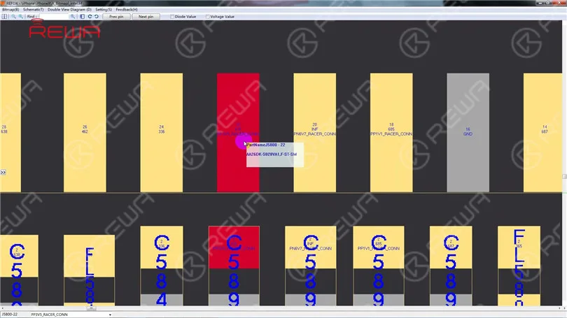
Possiamo notare che nel circuito è presente un induttore FL5893. Iniziamo con FL5893.
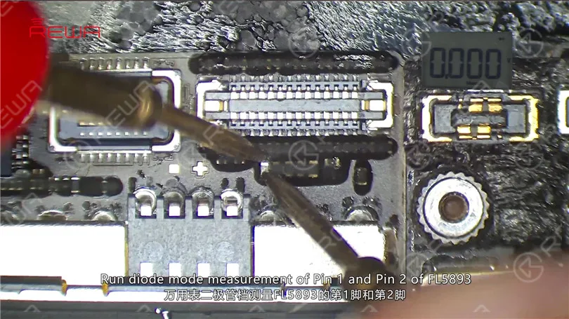
Innanzitutto, rimuovere la spugna intorno a J5800 con una pinzetta. Eseguire la misurazione in modalità diodo dei pin 1 e 2 di FL5893. Il valore misurato dei due pin è 0. A giudicare dal valore misurato, FL5893 è in stato normale.
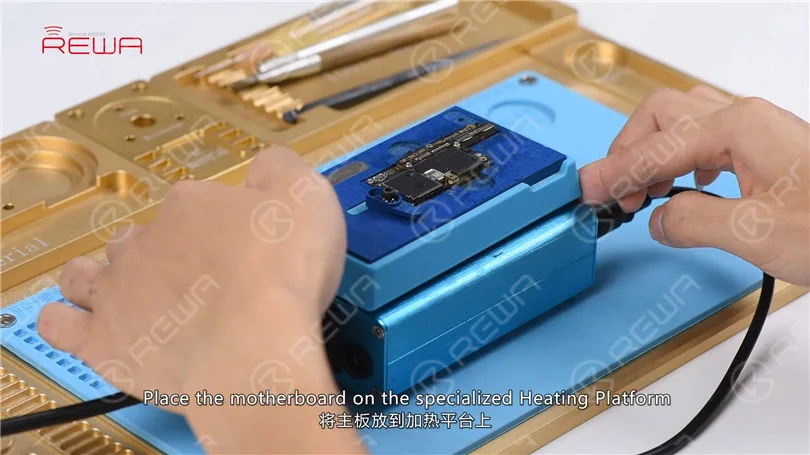
Possiamo vedere che il circuito si dirige verso il PCB del terzo spazio. È quindi necessario separare la scheda madre per controllare il PCB del terzo spazio. Posizionare la scheda madre sulla piattaforma di riscaldamento specializzata. Quando la temperatura della piattaforma raggiunge i 160℃, prelevare lo strato superiore con una pinzetta.
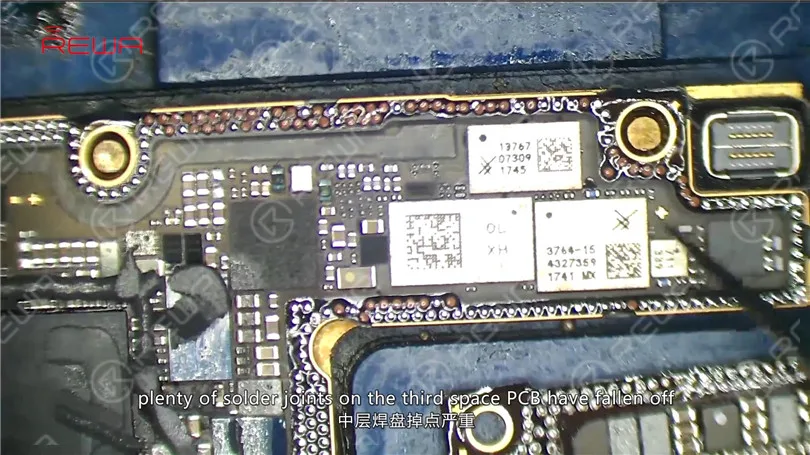
Come si può vedere, molte giunzioni di saldatura sulla scheda PCB del terzo spazio si sono staccate. E la scheda madre è gravemente deformata. A giudicare da questo, la scheda madre non è riparabile.
Conclusione:
Il touchscreen dell'iPhone X non risponde. La prima cosa da fare è controllare il connettore FPC del Touch ID J5800. Eseguire la misurazione in modalità diodo di J5800. A giudicare dal valore misurato, il circuito del pin 22 è aperto. Nella bitmap si può notare che il circuito si dirige verso il terzo spazio del PCB. Se si separa la scheda madre, si scopre che molti giunti di saldatura sul PCB del terzo spazio sono caduti. La scheda madre è inoltre gravemente deformata. A giudicare da questo, la scheda madre non è riparabile.
-
How to Fix iPhone X Bottom Speaker Not Working
Today we will share how to fix iPhone X bottom speaker not working.
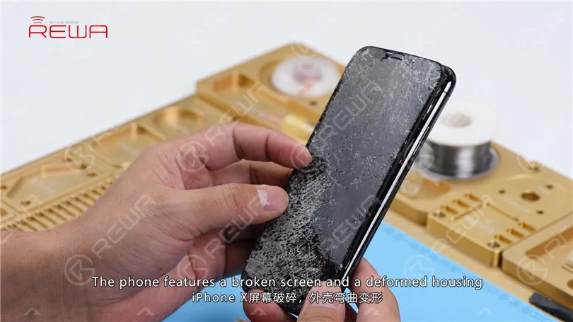
The phone features a broken screen and a deformed housing. Get a new display assembly installed and test. The phone turns on normally. Both the front camera and the rear camera work normally. WiFi also functions well.
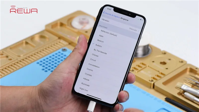
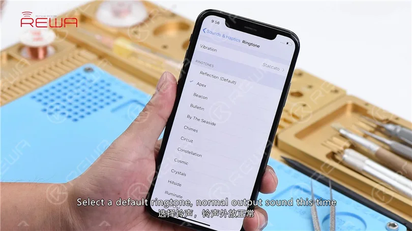
Go to Sounds & Haptics > Ringtone. Select a default ringtone and there is no output sound. But the sound works fine with headphones in.
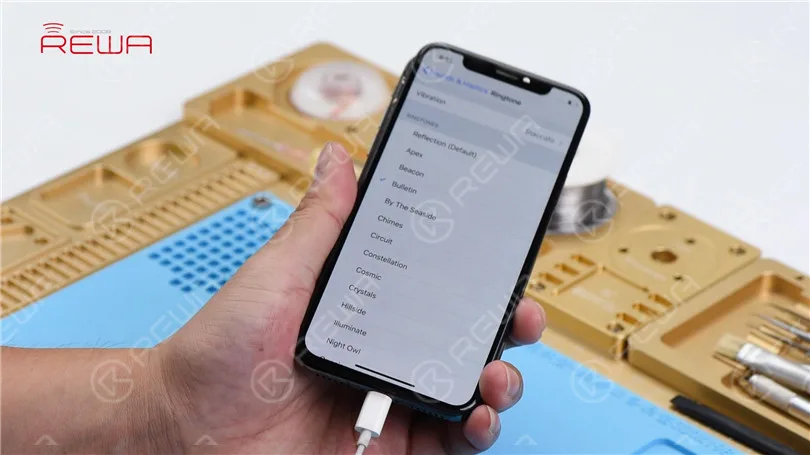
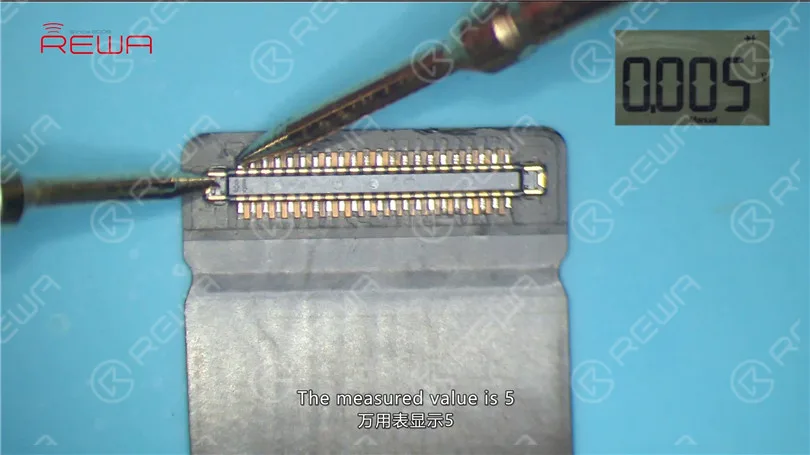
The preliminary judgment is that the audio circuit is in normal condition. It’s just that the bottom speaker is not working. Remove the display assembly and disconnect the battery. Disconnect the charging port flex cable. Run diode mode measurement of Pin 1 and Pin 45 of the DOCK connector. The measured value is 5, which indicates that the bottom speaker is in normal condition.
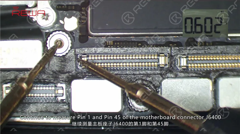
Continue to measure Pin 1 and Pin 45 of the motherboard connector J6400. The measured value of Pin 45 is 602, which is normal.
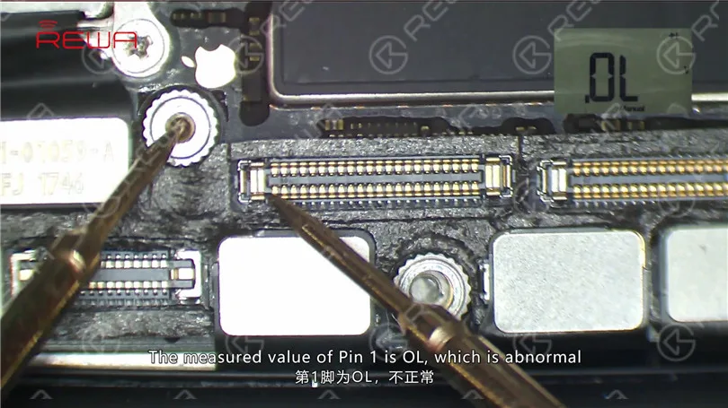
The measured value of Pin 1 is OL, which is abnormal.
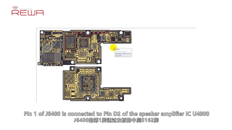
Judging by this, Pin 1 relevant circuit has been open-circuited. Pin 1 of J6400 is connected to Pin 2 of the speaker amplifier IC U4900 by way of Pin S162 on cylinders around the edge of the lower layer. So our next move is to check the circuit carefully. Disconnect flex cables on the motherboard and take out the motherboard. Fix the motherboard to the Holder. Heat with Hot Air Gun at 360℃, air flow 65.
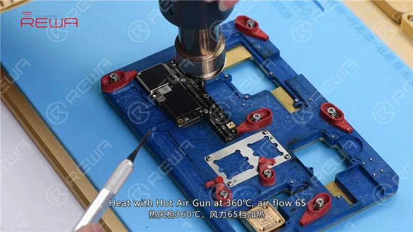
One minute later, pry up the upper layer step by step. Tips: make sure you pry up the upper layer at the right moment when tins on cylinders have melted. We can see clearly that there are multiple missing pins on the upper layer, including Pin S166 of the NFC circuit.
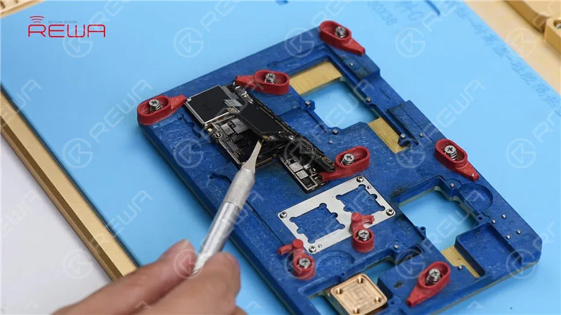
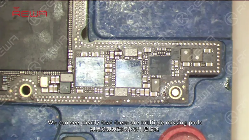
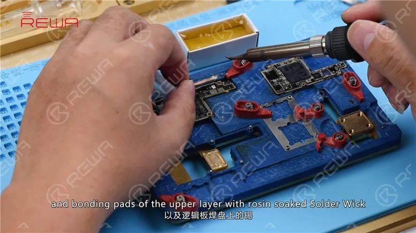
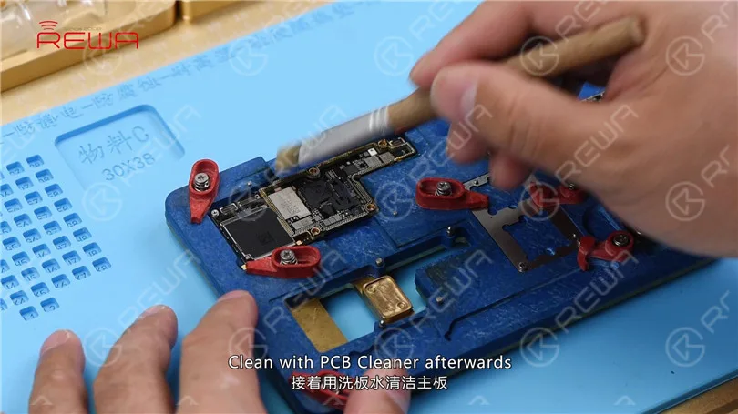
Judging by this, the phone has been dropped, which resulted in pseudo soldering of the motherboard accompanied with the detachment of pins. Since most of those missing pins are ground pins, we can just ignore them. Yet we need to treat Pin S166 with jumper wiring. Remove tins on cylinders around the edge of the lower layer and bonding pads of the upper layer with rosin soaked Solder Wick. Clean with PCB Cleaner afterwards.
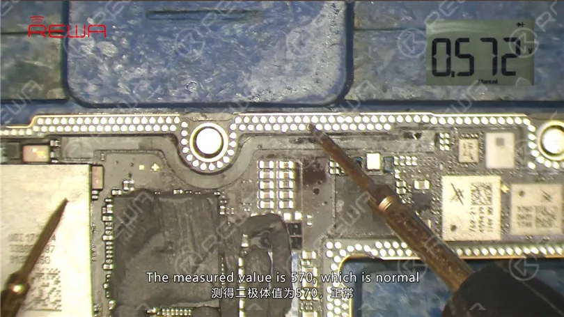
Run diode mode measurement of Pin S162 on cylinders. The measured value is 570, which is normal. Continue to measure Pin S163. The measured value is 570, which is normal. Judging by this, the open-circuited condition of Pin 1 relevant circuit is caused by pseudo soldering of cylinders around the edge of the lower layer.
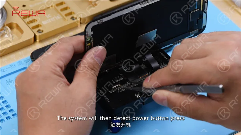
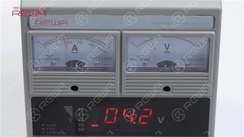
Now, let’s get the motherboard installed to the testing kit. Buckle up the extension flex cable of the display assembly. Then the charging port flex cable and the display assembly. Connect the battery connector with the DC Power Supply. Short Pin 9 of J4300 to the ground with tweezers. The system will then detect power button press. Current reading on the ammeter is normal.
Go to Settings > Sounds & Haptics > Ringtone. Select a default ringtone. Normal output sound this time.
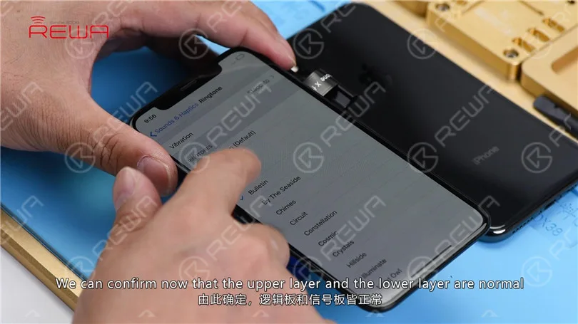
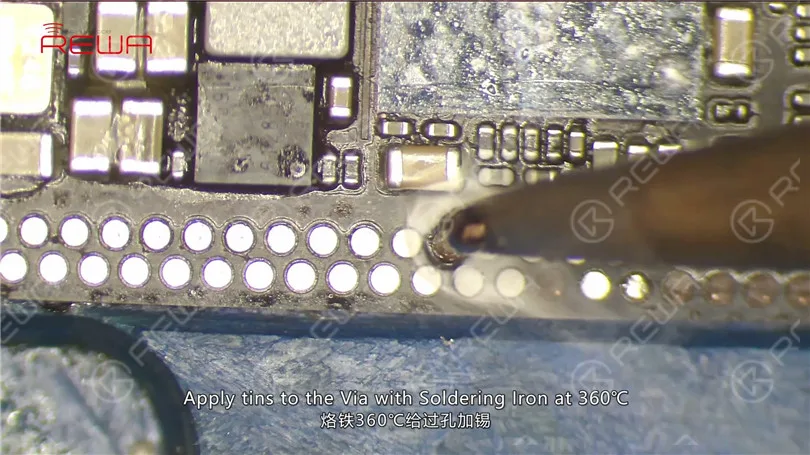
We can confirm now that the upper layer and the lower layer are normal. And the fault is caused by pseudo soldering of cylinders. We can fix the problem by soldering the two layers together. Also before soldering, we need to treat Pin S166 with jumper wiring. Apply tins to the Via with Soldering Iron at 360℃. Prepare a length of tin applied Enameled Copper Wire of 0.02mm in diameter. Solder one end to the tin applied Via.
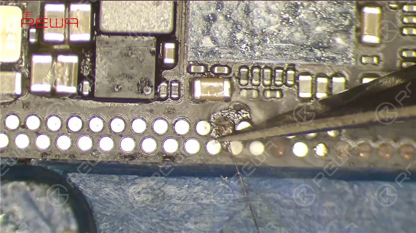
Clean with PCB Cleaner afterwards. Then apply some UV Curable Solder Mask to the soldered area. And solidify the upper layer under Lampada UV per essiccazione for 2 minutes.
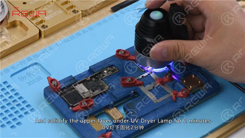
Then get the other end to the right position. Next, attach the lower layer to PCB Holder. Fix the BGA Reballing Stencil to the right position. Smear Soldering Paste evenly on the BGA reballing stencil with BGA Scraper. Wipe out excess Soldering Paste with lint-free wiping cloth.
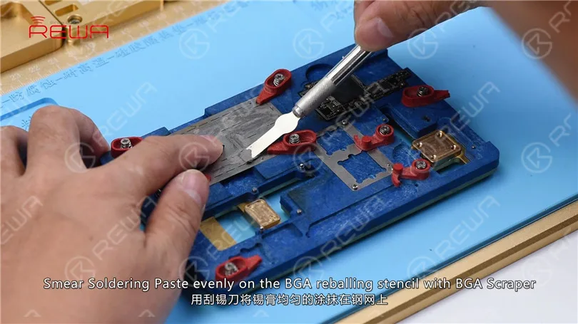
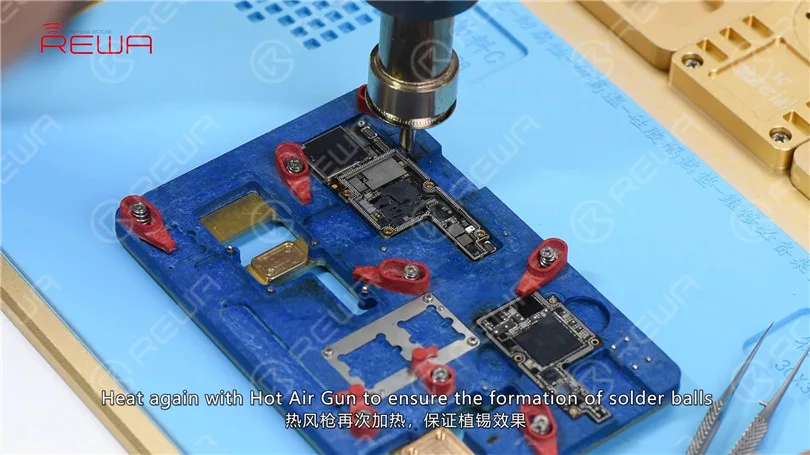
Then heat evenly with Hot Air Gun at 350℃, air flow 35. So that all solder balls can solidify completely. Remove the BGA reballing stencil after 2 minutes. Heat again with Hot Air Gun to ensure the formation of solder balls.
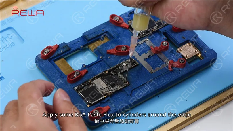
Apply some BGA Paste Flux to cylinders around the edge and get the upper layer in position.
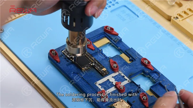
Heat evenly with Hot Air Gun at 350℃, air flow 65. The soldering process is finished with the upper layer sinking and Paste Flux overflowing.
Wait for the motherboard to cool for 5 minutes. Now, let’s assemble the phone and test. Go to Settings>Sounds&Haptics>Ringtone. Select a default ringtone, normal output sound this time.
-
REWA Deep Test for iPhone X Aftermarket LCD Screen
Many people in the cell phone repair industry have expectations for iPhone X aftermarket screen to reduce the repair cost of iPhone X screen repair. Since iPhone X is different with previous models, the difficulty of iPhone X aftermarket screen production is quite high. After fully tested the first batch of iPhone X LCD aftermarket screens, REWA shares our test results with you for your information.
-
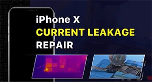
Come risolvere il problema della batteria dell'iPhone X che si scarica velocemente - Il difetto si nasconde sotto il lettore di schede
La batteria dell'iPhone X si sta scaricando rapidamente con un problema di surriscaldamento. Dopo la misurazione, si è scoperto che la scheda madre presenta una dispersione di corrente. Poiché la corrente è troppo piccola, il rilevamento della colofonia non è in grado di individuare il guasto. Pertanto, utilizziamo una termocamera per individuare la parte difettosa. Dopo vari controlli, si scopre che la parte difettosa si trova sotto il lettore di schede.
-
iPhone Motherboard Repair Live Course Preview
The iPhone Motherboard Repair Live Course is suitable for iPhone motherboard repair beginners. The course includes troubleshooting methods and demo repair for common motherboard problems. In the meantime, we offer continuous technical support for your learning. Join REWA Academy live course on 6 Sept to enrich your repair knowledge.
-
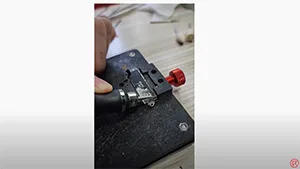
Entra nel Taptic Engine dell'iPhone
Una combinazione di “tap” (tocco) e “haptic feedback” (feedback aptico), il Taptic Engine è una tecnologia creata da Apple per fornire agli utenti sensazioni tattili sotto forma di vibrazioni. Quindi cosa c'è dentro il Taptic Engine? Guarda questo video per scoprirlo!
 English
 Español
 Français
 Deutsch
 Italiano