Tag: iphone won’t turn on

  • Guida alla riparazione del problema di iPhone 12 Pro Max che non si accende

    Guida alla riparazione dell'iPhone 12 Pro Max che non si accende

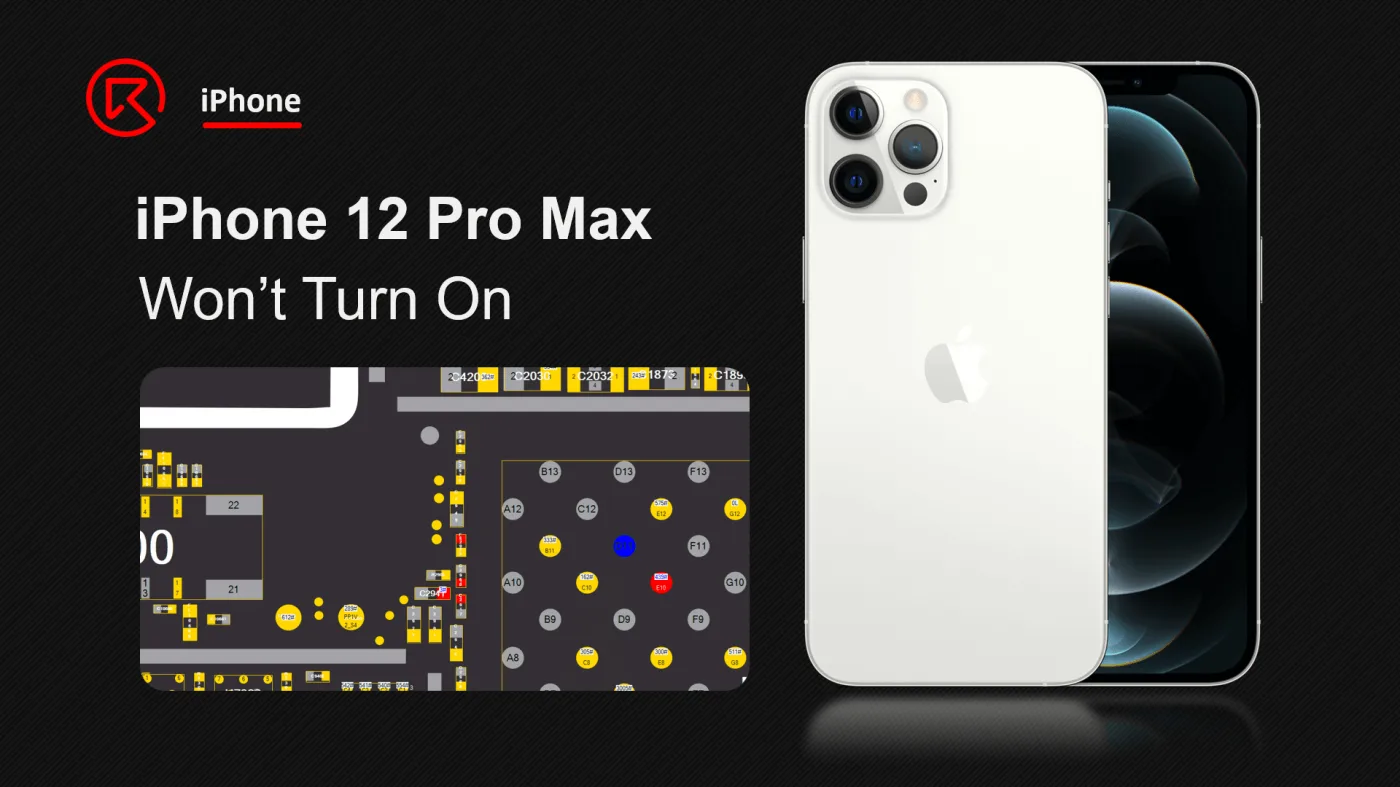
    L'iPhone 12 Pro Max, annunciato il 13 ottobre 2020, è uno smartphone di fascia alta noto per le sue funzioni avanzate. Tuttavia, una caduta grave può causare l'impossibilità di accenderlo. Questa guida illustra i passaggi per risolvere e riparare questo problema.
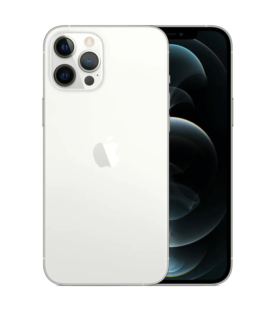
    iphone 12 pro max cannot charge stuck apple logo

    Dettagli telefonici

    Modello: iPhone 12 Pro Max

    Annunciato: 2020, 13 ottobre

    Fenomeno dei difetti

    Un iPhone 12 Pro Max gravemente danneggiato da una caduta potrebbe non accendersi. In questi casi, la seguente procedura di risoluzione dei problemi e di riparazione può essere utile.

    Processo di risoluzione dei problemi

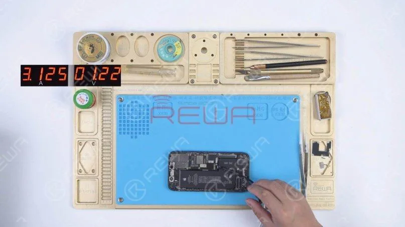
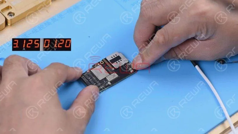
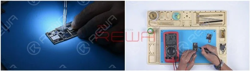
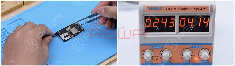
    Per prima cosa, colleghiamo la scheda madre con l'alimentatore CC, non c'è perdita di corrente. Ma quando si attiva il processo di avvio con una pinzetta, la corrente salta direttamente a 1100mA.
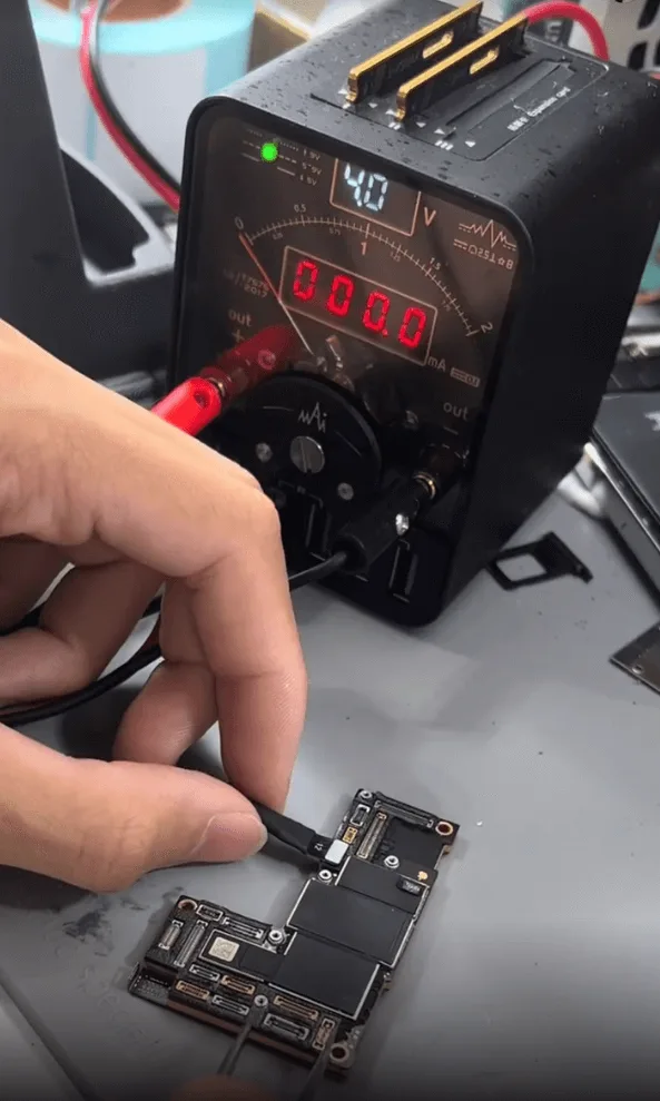
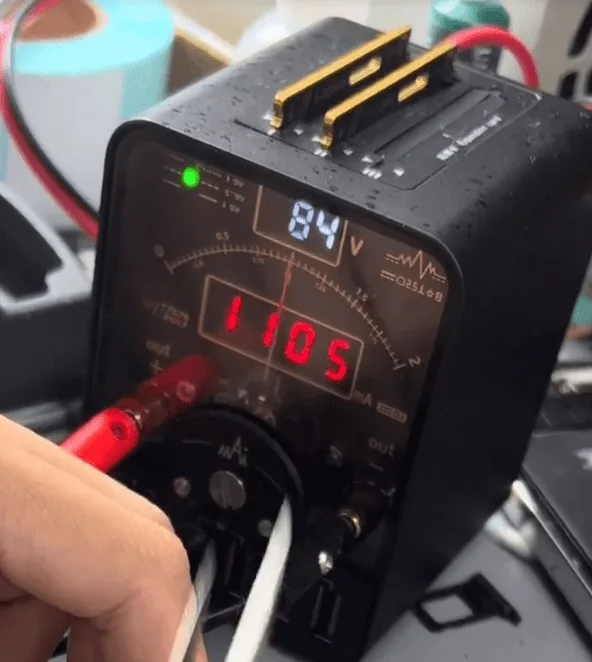
    iphone 12 pro max won turn issue repair guide trigger to boot
    iphone 12 pro max won turn issue repair guide 1100ma directly

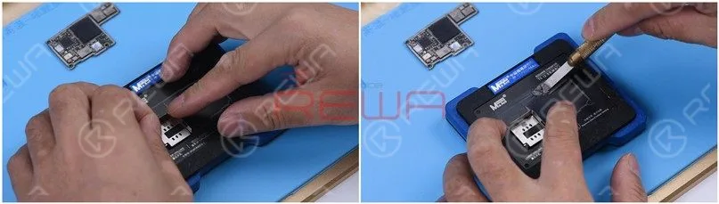
    Quindi, rimuoviamo le schiume intorno ai connettori e teniamo la scheda madre sulla piattaforma di riscaldamento per separare i due strati della scheda madre.
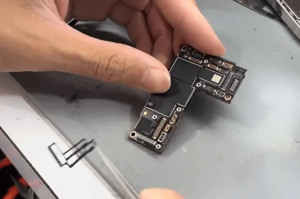
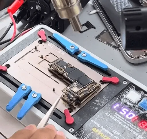
    iphone 12 pro max won turn issue repair guide remove the foams around
    iphone 12 pro max won turn issue repair guide separate with the heating

    Dopo la separazione, non sorprende che molti cuscinetti si siano staccati; in seguito dovremo dedicare molto tempo a sistemare i cuscinetti mancanti. In ogni caso, risolviamo prima il problema dello stivale.

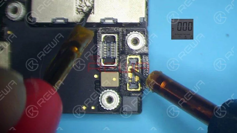
    Quando si misurano i valori dei diodi sui binari di alimentazione in uscita dalla PMU alla CPU, si scopre che un condensatore intorno alla CPU è cortocircuitato a terra.
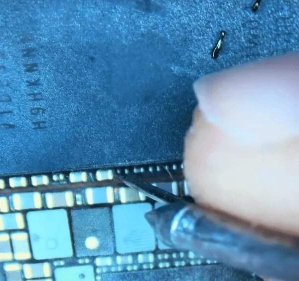
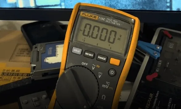
    iphone 12 pro max won turn issue repair guide when measuring with
    iphone 12 pro max won turn issue repair guide find one rail is shorted

    Fare riferimento al Bitmap di Refoxè PP1V2_IO.

    Come possiamo vedere, ci sono molti componenti legati al PP1V2_IO.
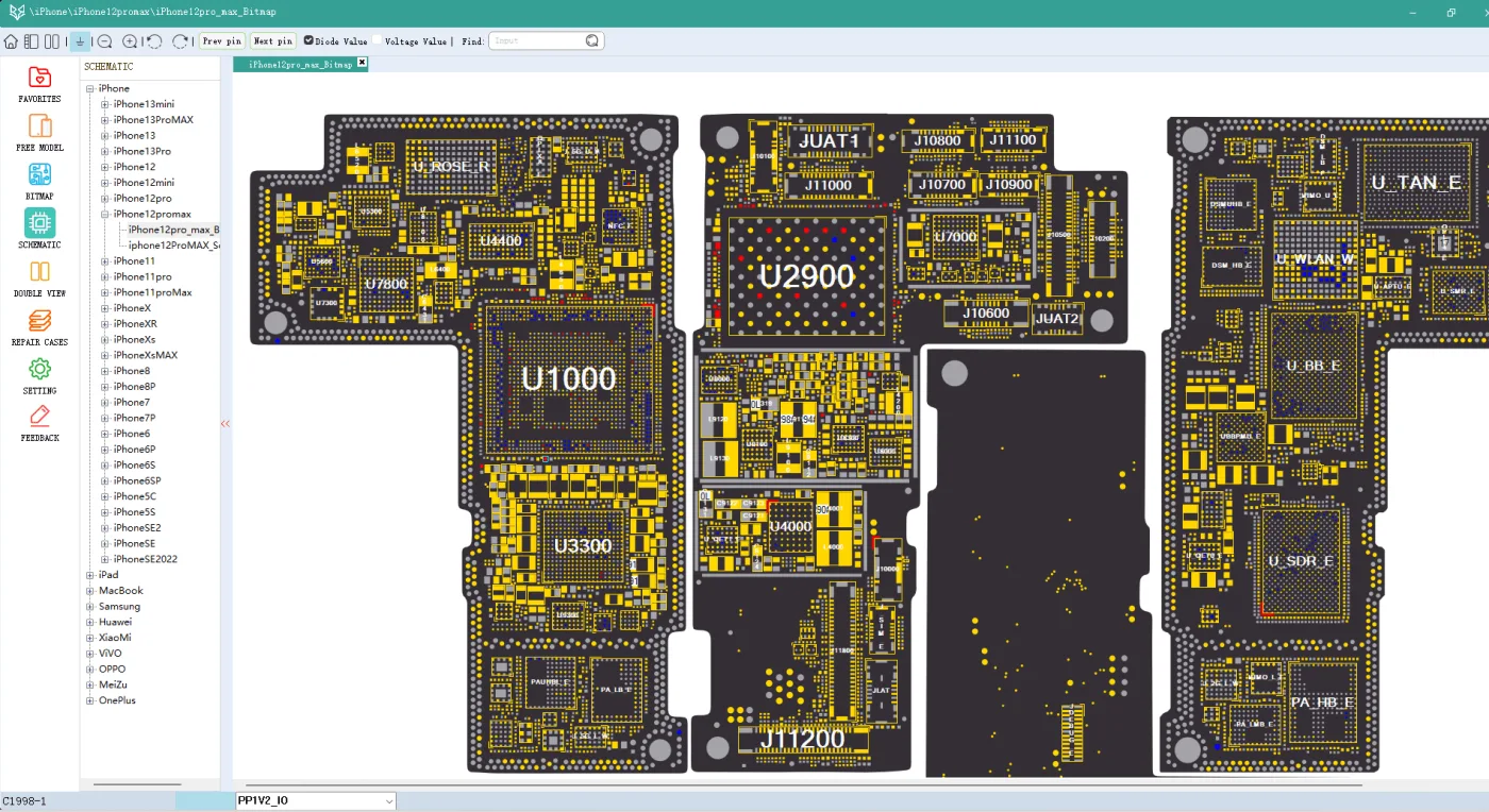
    iphone 12 pro max won turn issue repair guide refox bitmap

    Per individuare l'esatto componente in cortocircuito, è necessario utilizzare il metodo di ispezione della colofonia.

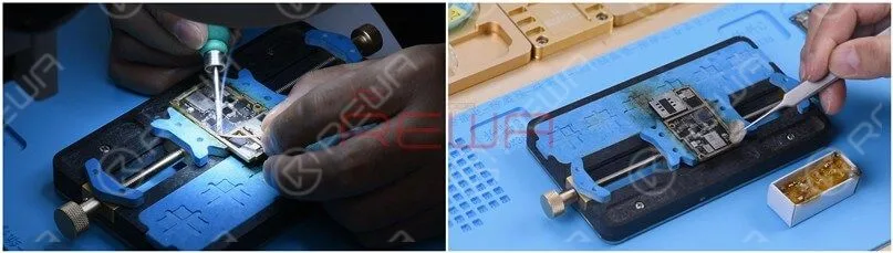
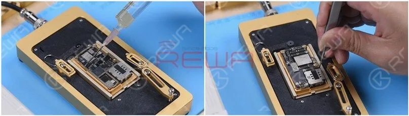
    Applicare il fumo di colofonia sulla superficie delle aree interessate della scheda madre.
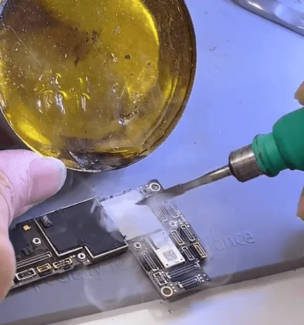
    iphone 12 pro max won turn issue repair guide apply rosin smoke on the

    Quindi collegare la scheda madre con l'alimentatore CC e controllare al microscopio, per trovare facilmente il componente in cortocircuito.
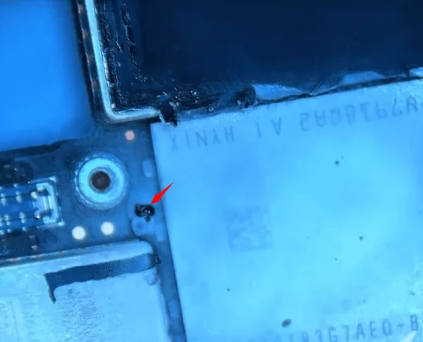
    iphone 12 pro max won turn issue repair guide the shorted capacitor

    Fare riferimento alla bitmap, si tratta del condensatore C2941
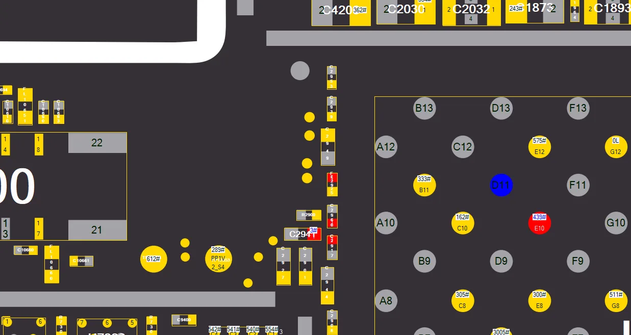
    iphone 12 pro max won turn issue repair guide c2941

    Poiché si tratta di un condensatore di tipo filtrante, per evitare di danneggiare con il calore la NAND e i connettori che la circondano. Possiamo rimuoverlo direttamente con una pinzetta.

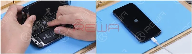
    Successivamente, collegare la scheda logica con lo schermo e avviare di nuovo la macchina con l'alimentazione CC, il telefono può essere avviato.
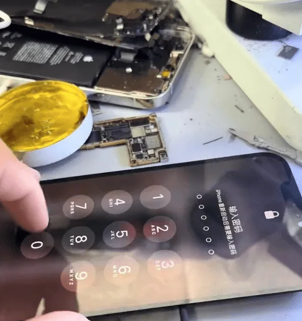
    iphone 12 pro max won turn issue repair guide phone can be booted

    Quindi, sistemiamo i rilievi mancanti sullo strato centrale.
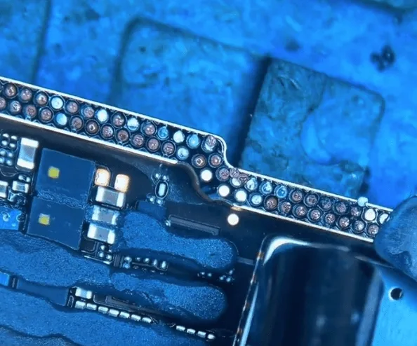
    iphone 12 pro max won turn issue repair guide the missing pads on middle

    Riparare i cuscinetti mancanti non è molto difficile, ma richiede molta pazienza.

    Per il pad che non ha un punto di connessione
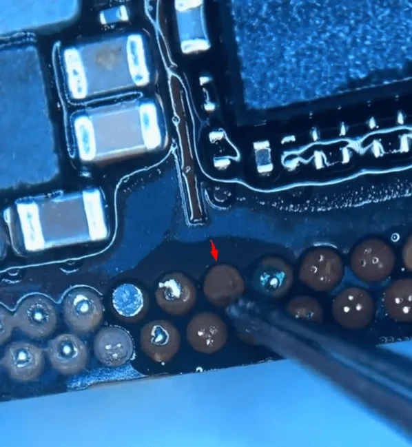
    iphone 12 pro max won turn issue repair guide for the pad that has no

    Prima è necessario grattare leggermente la radice del cuscinetto con un coltello da scultura.
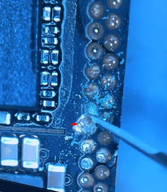
    iphone 12 pro max won turn issue repair guide scratch out the pads

    Dopo di che, sulla base della "radice" per saltare il filo e fare un cerchio
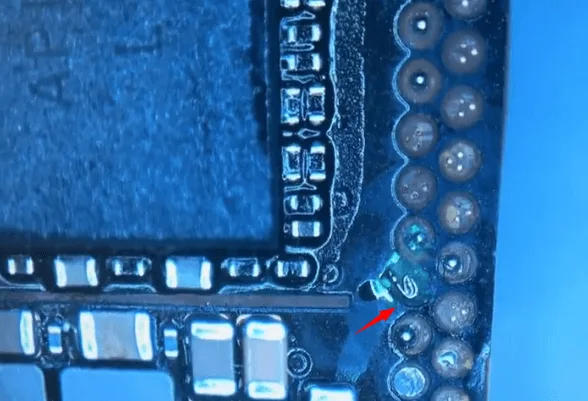
    iphone 12 pro max won turn issue repair guide make circle

    Quindi saldare un capocorda di rame sulla superficie
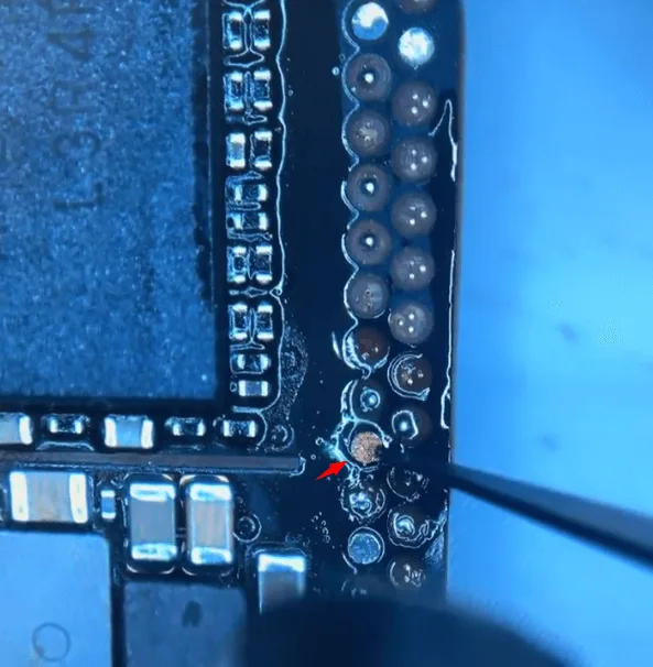
    iphone 12 pro max won turn issue repair guide solder copper lug on the

    Quindi polimerizzare e rinforzare con la maschera UV e la lampada UV.
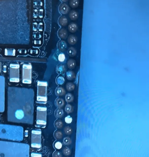
    iphone 12 pro max won turn issue repair guide cure with the uv lamp

    Assemblaggio e test

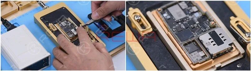
    Quindi assemblare i due strati della scheda madre prima con la piattaforma di riscaldamento
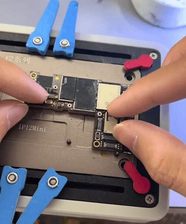
    iphone 12 pro max won turn issue repair guide heating platform

    Quando la scheda madre si raffredda, assemblare il telefono per testare e tutte le funzioni sono OK.

    Il problema si risolve rimuovendo il condensatore danneggiato e ricombinando i due strati della scheda madre.
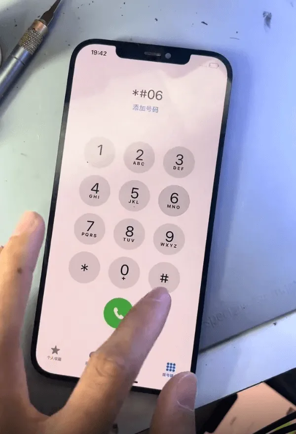
    L'iPhone 12 Pro Max non si accende

    Sintesi

    Il problema dell'iPhone 12 Pro Max che non si accendeva a causa di un grave danno da caduta è stato risolto da:

    • Rimozione del condensatore danneggiato (C2941).
    • Ricombinazione dei due strati della scheda madre.
    • Fissare i cuscinetti mancanti.

    Questa riparazione richiede un'ispezione accurata e un lavoro preciso per garantire il ripristino della piena funzionalità del telefono senza causare ulteriori danni.
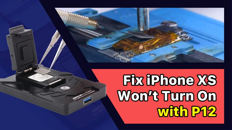
  • Risolvi il problema dell'iPhone XS che non si accende con P12 (Programmatore NAND per iPhone 6 – iPhone 11 Pro Max)

    Risolvi il problema dell'iPhone XS che non si accende con P12 (Programmatore NAND per iPhone 6 – iPhone 11 Pro Max)

    NAND replacement is a common repair procedure in iPhone repair, whether for storage upgrade or fixing issues like not turning on caused by a damaged NAND. For NAND replacement, a NAND programmer is needed to read and write the NAND data.
    Fix iPhone XS Won't Turn On with P12 (NAND Programmer for iPhone 6 - iPhone 11 Pro Max)

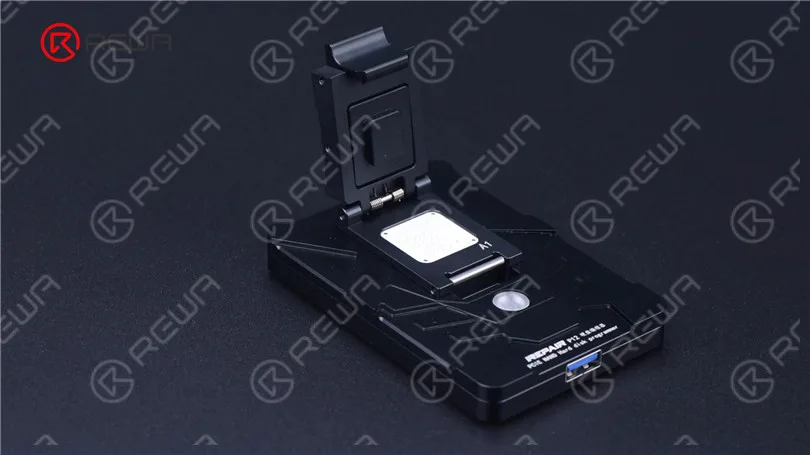
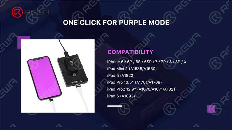
    Today we will repair an iPhone with the latest NAND programmer P12, Compared to other NAND programmers on the market, P12 supports a wide array of models, which includes NAND read & write and WiFi unbinding for iPhone 6-iPhone 11 Pro Max and some iPad models. What’s more, P12 can work without an internet connection and is free for use permanently.

    Fix iPhone XS Won't Turn On with P12 (NAND Programmer for iPhone 6 - iPhone 11 Pro Max)
    Fix iPhone XS Won't Turn On with P12 (NAND Programmer for iPhone 6 - iPhone 11 Pro Max)
    Fix iPhone XS Won't Turn On with P12 (NAND Programmer for iPhone 6 - iPhone 11 Pro Max)

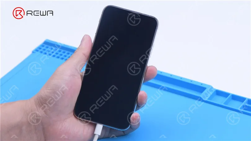
    Then we use P12 to fix an iPhone XS that won’t turn on. The iPhone XS is unable to boot up.

    Fix iPhone XS Won't Turn On with P12 (NAND Programmer for iPhone 6 - iPhone 11 Pro Max)

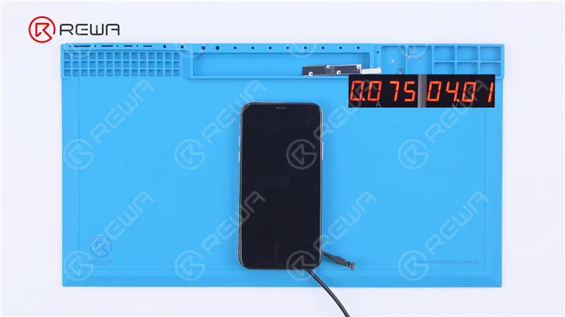
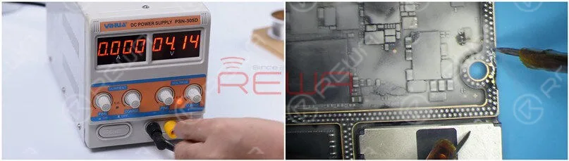
    Then we disassemble the phone for further testing. Connect the motherboard with Cavo di alimentazione. The boot current only has 75 mA. It can be preliminarily judged that the system is faulty.

    Fix iPhone XS Won't Turn On with P12 (NAND Programmer for iPhone 6 - iPhone 11 Pro Max)

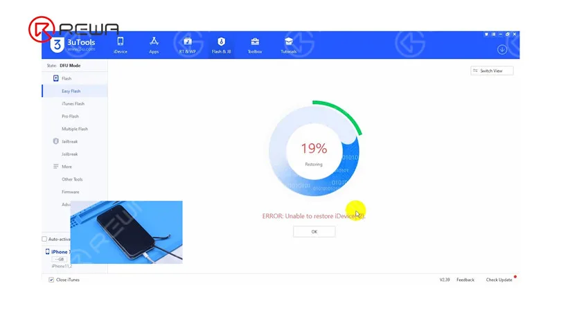
    Next, connect the phone with the computer. The phone is in DFU mode automatically. The flashing gets stuck at 19%. We can confirm now that the not turning issue is induced by faulty circuits related to the NAND.

    Fix iPhone XS Won't Turn On with P12 (NAND Programmer for iPhone 6 - iPhone 11 Pro Max)

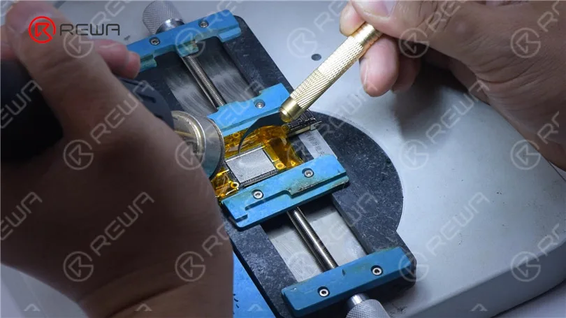
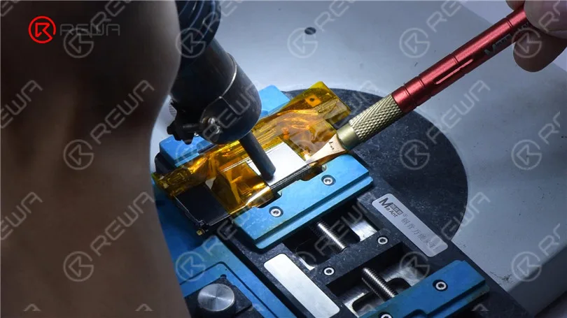
    The next step is to replace the NAND with a new one. Remove the display and detach the motherboard. Apply high-temperature tape around the motherboard. First of all, remove black adhesive around the NAND with Hot Air Gun at 280 °C.

    Fix iPhone XS Won't Turn On with P12 (NAND Programmer for iPhone 6 - iPhone 11 Pro Max)

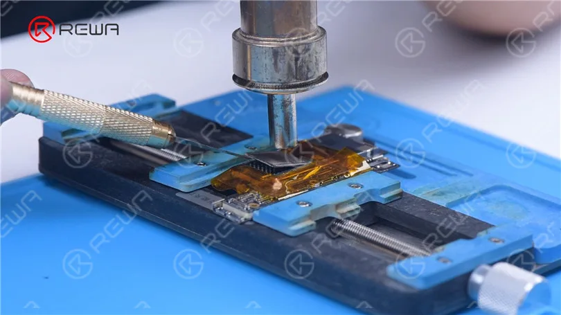
    Pry up the NAND with Hot Air Gun at 400 °C.

    Fix iPhone XS Won't Turn On with P12 (NAND Programmer for iPhone 6 - iPhone 11 Pro Max)

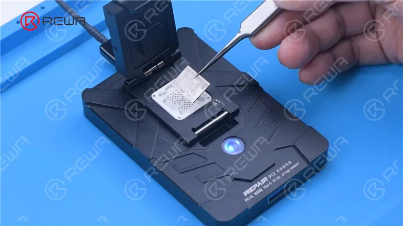
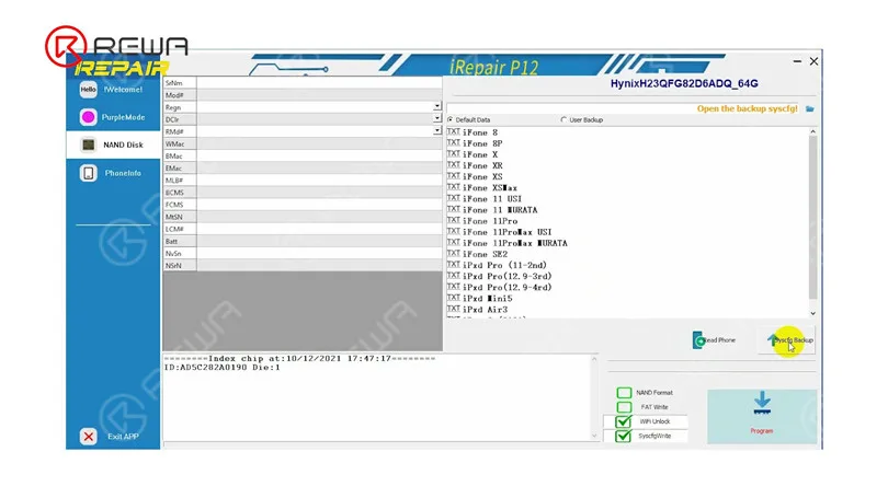
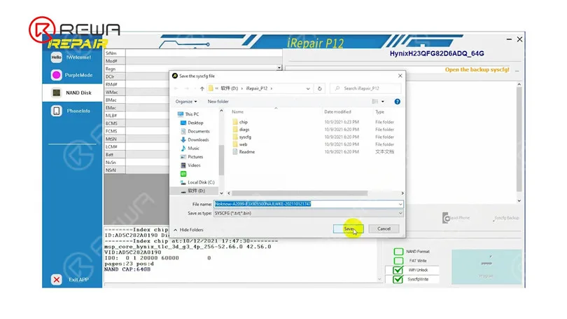
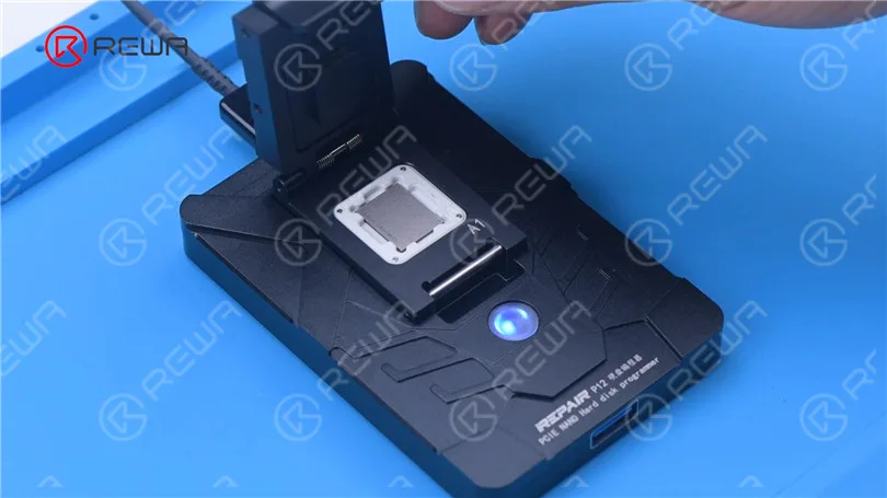
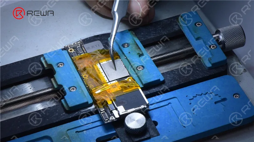
    Attach the NAND to P12. Please pay attention to aligning the NAND with the A1 pin. Click “Syscfg Backup”. Then save the data.

    Fix iPhone XS Won't Turn On with P12 (NAND Programmer for iPhone 6 - iPhone 11 Pro Max)
    Fix iPhone XS Won't Turn On with P12 (NAND Programmer for iPhone 6 - iPhone 11 Pro Max)
    Fix iPhone XS Won't Turn On with P12 (NAND Programmer for iPhone 6 - iPhone 11 Pro Max)

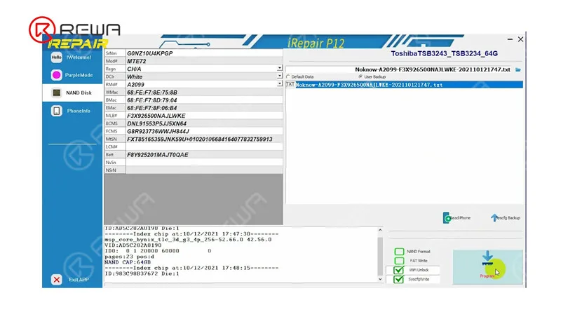
    Remove the NAND. Attach the new NAND to P12. Select “User Backup”. Tap “Program”.

    Fix iPhone XS Won't Turn On with P12 (NAND Programmer for iPhone 6 - iPhone 11 Pro Max)
    Fix iPhone XS Won't Turn On with P12 (NAND Programmer for iPhone 6 - iPhone 11 Pro Max)

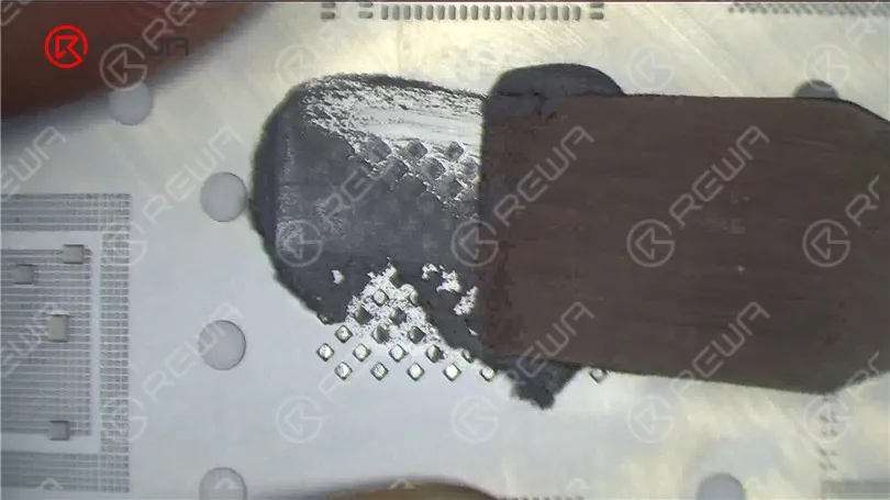
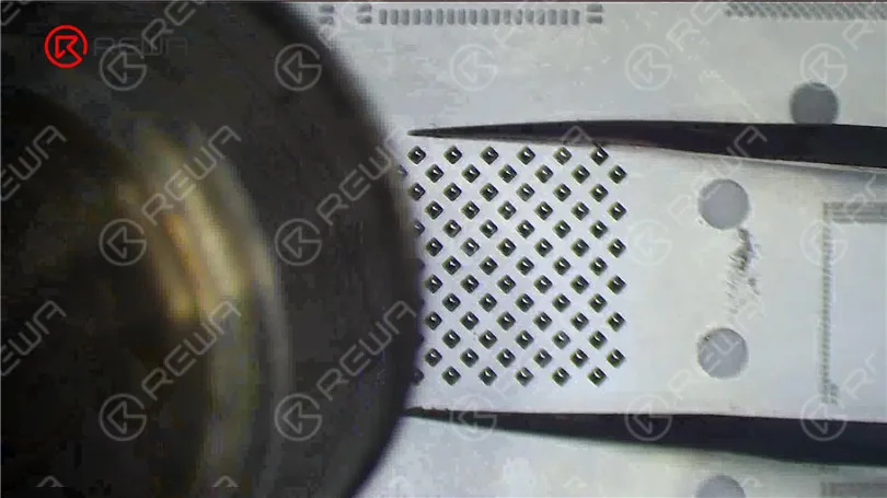
    Next, we reball the NAND with the written data. Place the reballing stencil in position. Apply a layer of middle-temperature Solder Paste evenly. Heat with Hot Air Gun at 340 °C.

    Fix iPhone XS Won't Turn On with P12 (NAND Programmer for iPhone 6 - iPhone 11 Pro Max)
    Fix iPhone XS Won't Turn On with P12 (NAND Programmer for iPhone 6 - iPhone 11 Pro Max)

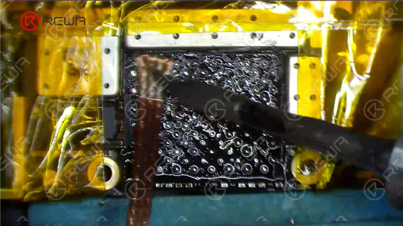
    Before NAND soldering, we need to remove tin on the bonding pads. Apply some middle-temperature Solder Paste with Soldering Iron. Clean the bonding pads with Soldering Iron and Solder Wick.

    Fix iPhone XS Won't Turn On with P12 (NAND Programmer for iPhone 6 - iPhone 11 Pro Max)

    Remove black adhesive on the bonding pads with Sculpture Knife. Then clean the bonding pads with PCB Cleaner. After cleaning, apply some Paste Flux

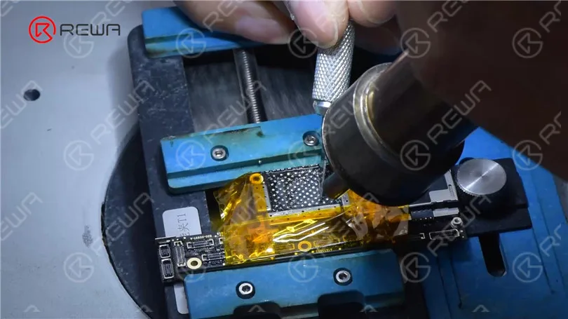
    Align the new NAND. Heat with Hot Air Gun at 380 °C to solder.

    Fix iPhone XS Won't Turn On with P12 (NAND Programmer for iPhone 6 - iPhone 11 Pro Max)
    Fix iPhone XS Won't Turn On with P12 (NAND Programmer for iPhone 6 - iPhone 11 Pro Max)

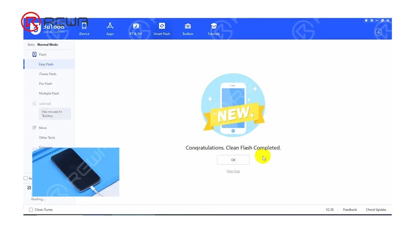
    Then we install the motherboard. Connect the phone with the computer to flash. The flashing has been successful.

    Fix iPhone XS Won't Turn On with P12 (NAND Programmer for iPhone 6 - iPhone 11 Pro Max)

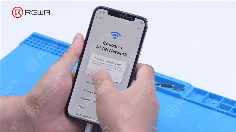
    The phone turns on normally. After activation, the phone also functions well.

    Fix iPhone XS Won't Turn On with P12 (NAND Programmer for iPhone 6 - iPhone 11 Pro Max)
  • Fix iPhone 7/7 Plus Won’t Turn On – CPU Repair

    Fix iPhone 7/7 Plus Won’t Turn On – CPU Repair

    iPhone 7/7 Plus won’t turn on after it is dropped? Due to the imperfect technology of CPU supplier, the SDRAM of iPhone 7/7 Plus series can be easily damaged. Once dropped, the SDRAM might be short circuited and the phone won’t turn on afterwards. The traditional SDRAM replacing method is complex and easy to get it pseudo soldered. This time we introduced a new solution with CNC Chip Grinding Machine. Let’s check the video to see how we fix iPhone 7 plus won’t power on issue in a more efficient way.

  • Fix iPhone 12 Won’t Turn On By Infrared Thermal Imaging Camera

    Fix iPhone 12 Won’t Turn On By Infrared Thermal Imaging Camera

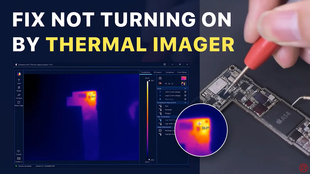
    Today we will share a repair case of an iPhone 12 that won’t turn on. After multiple attempts to turn on the iPhone 12, the iPhone 12 still won’t turn on. We have excluded the possibility of the display assembly and battery faults, so we speculate the cause is the short circuit of the motherboard. To find the faulty part, we have used the latest infrared thermal imager camera that differs from the complicated rosin detecting. Let’s check it out!

  • How to Fix an iPhone 11 Pro Won’t Turn On

    How to Fix an iPhone 11 Pro Won’t Turn On

    Having trouble with your iPhone 11 Pro refusing to turn on? Don’t worry, we’ve got your back! In this comprehensive guide, we’ll walk you through some practical and effective solutions to fix this frustrating issue.

    Step 1: Disassemble and test

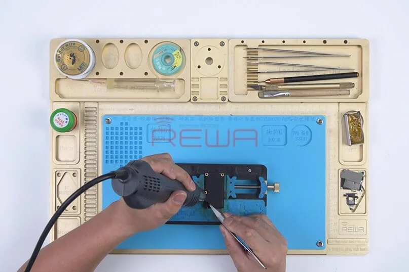
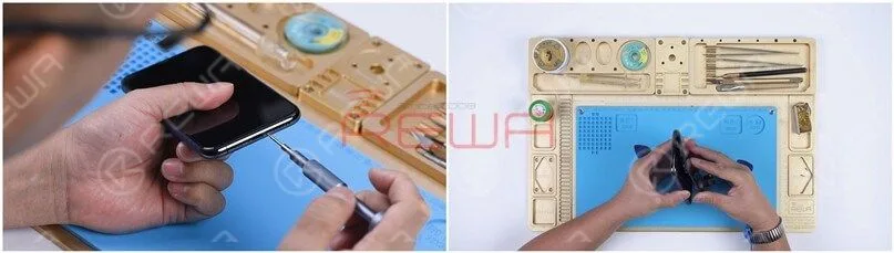
    Remove the two pentalobe screws at the bottom edge and lift the screen.
    Remove the two pentalobe screws at the bottom edge and lift the screen.

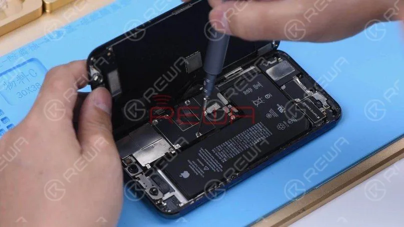
    After the screen is lifted, take the shielding covers off, disconnect the battery, and remove the screen.
    After the screen is lifted, take the shielding covers off, disconnect the battery, and remove the screen.

    Connect the motherboard with the Power Cable. The ammeter shows a large current of 3.1A.
    Connect the motherboard with the Power Cable. The ammeter shows a large current of 3.1A.

    Detach the motherboard and connect the motherboard with the Power Cable again. The ammeter still shows a large current of 3.1A.
    Detach the motherboard and connect the motherboard with the Power Cable again. The ammeter still shows a large current of 3.1A.

    It indicates that the large current has nothing to do with other flex cables. The fault is on the motherboard.

    Fase 2: Esecuzione della misura in modalità diodo

    Run diode mode measurement of pin 1 on the J7010 of the battery connector. The diode value is 0 which indicates that the main power supply circuit is shorted to the ground.

    Run diode mode measurement of pin 1 on the J7010 of the battery connector. The diode value is 0 which indicates that the main power supply circuit is shorted to the ground.

    Poiché il circuito fornisce contemporaneamente alimentazione alla logic board e alla signal board, dobbiamo separare la motherboard per localizzare il guasto.

    Fase 3: separazione della scheda madre

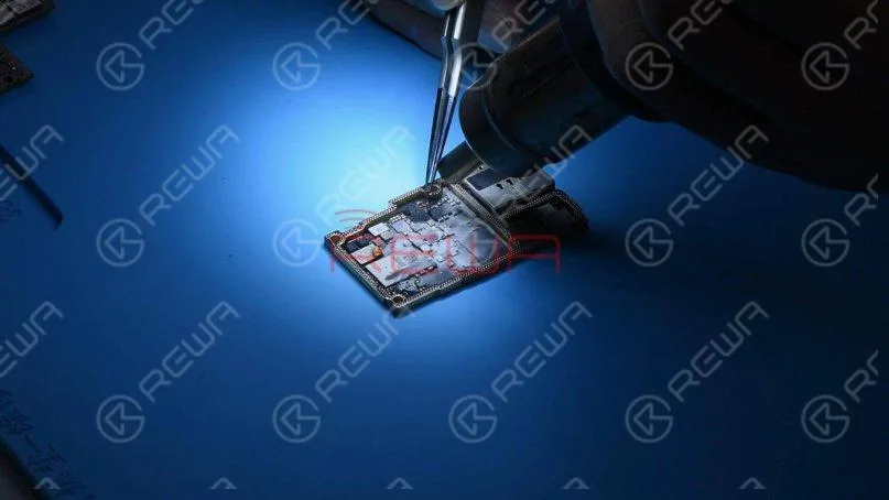
    Remove foam on the motherboard. Then heat the back of the motherboard with Pistola ad aria calda at 240℃ to remove the shielding paper.
    Remove foam on the motherboard. Then heat the back of the motherboard with Hot Air Gun at 240℃ to remove the shielding paper.

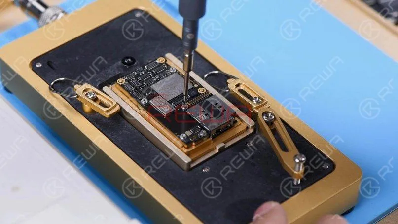
    Metti la scheda madre su Piattaforma di riscaldamento. To make it easier to remove the logic board after separation, drive a screw on the logic board.
    Put the motherboard on the Heating Platform. To make it easier to remove the logic board after separation, drive a screw on the logic board.

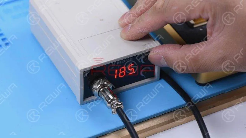
    Set the temperature of the Heating Platform to 185℃.

    Set the temperature of the Heating Platform to 185℃.

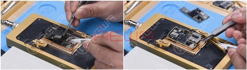
    Clamp the screw to remove the logic board when the temperature has risen to 185℃. Lastly, remove the signal board.
    Clamp the screw to remove the logic board when the temperature has risen to 185℃. Lastly, remove the signal board.

    Fase 4: Eseguire nuovamente la misurazione in modalità diodo

    Run diode mode measurement of pin 286 on the signal board. The diode value is 0. It suggests that the main power supply of the signal board is shorted to the ground.

    Run diode mode measurement of pin 286 on the signal board. The diode value is 0. It suggests that the main power supply of the signal board is shorted to the ground.

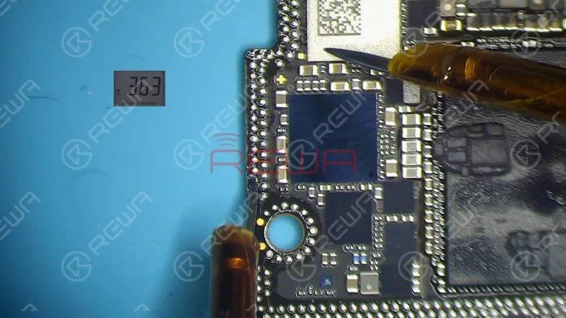
    Measure pin 286 on the logic board. The diode value is 363 which means the logic board is normal.

    Measure pin 286 on the logic board. The diode value is 363 which means the logic board is normal.

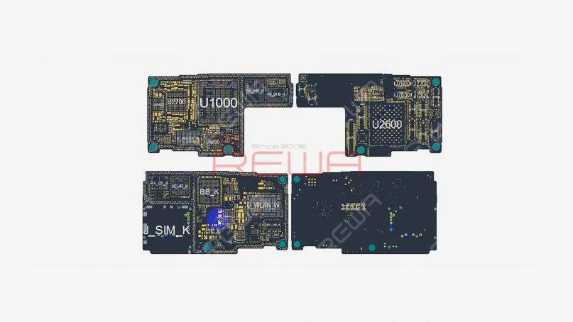
    Open the bitmap. We can see there are many associated components on the main power supply circuit.

    Apri la bitmap. Possiamo vedere che ci sono molti componenti associati sul circuito dell'alimentatore principale.

    Step 5: Rosin detecting to locate the fault

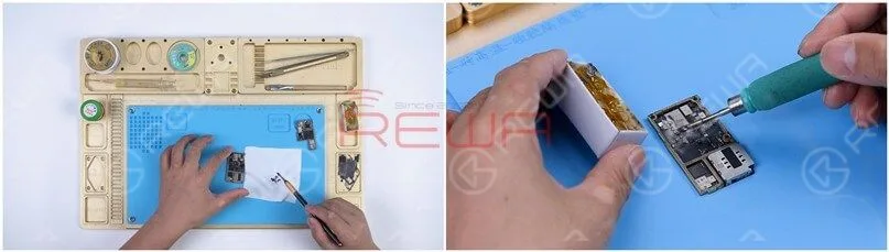
    Next, we need to locate the faulty component with rosin detecting.Remove thermal grease with a Sculpture Knife. Then dip rosin with Saldatore at 365℃ and smoke rosin on the signal board.

    Next, we need to locate the faulty component with rosin detecting.Remove thermal grease with a Sculpture Knife. Then dip rosin with Soldering Iron at 365℃ and smoke rosin on the signal board.

    Set the direct current supply to 4.1V. Connect the positive and negative anode of the direct current supply with multimeter probes. Connect the black probe to the ground and connect the red probe to pin 286 on the signal board. We can see rosin on C1200_K has melted. It indicates that the capacitor is damaged.

    Set the direct current supply to 4.1V. Connect the positive and negative anode of the direct current supply with multimeter probes. Connect the black probe to the ground and connect the red probe to pin 286 on the signal board. We can see rosin on C1200_K has melted. It indicates that the capacitor is damaged.

    Step 6: Eliminate the fault and restore the motherboard

    Then we heat the damaged capacitor with Hot Air Gun at 350℃ and remove it with tweezers.

    Then we heat the damaged capacitor with Hot Air Gun at 350℃ and remove it with tweezers.

    Pulisci la colofonia sulla scheda del segnale con il pulitore per PCB. Esegui una seconda misurazione in modalità diodo. Il valore del diodo ritorna a un valore normale di 327.

    Pulisci la colofonia sulla scheda del segnale con il pulitore per PCB. Esegui una seconda misurazione in modalità diodo. Il valore del diodo ritorna a un valore normale di 327.

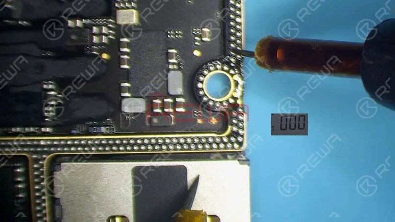
    Smear rosin with Soldering Iron and solder wick at 365℃ to remove tin on the bonding pad. Clean the signal board with PCB Cleaner.

    Smear rosin with Soldering Iron and solder wick at 365℃ to remove tin on the bonding pad. Clean the signal board with PCB Cleaner.

    Remove tin and clean the logic board with the same method.Attach the signal board to the Piattaforma di Reballing and put the Reballing Stencil in position. To prevent the solder paste from flowing into the motherboard crevices, insert a metal plate. Apply a layer of low-temperature Pasta saldante. 

    Remove tin and clean the logic board with the same method.Attach the signal board to the Reballing Platform and put the Reballing Stencil in position. To prevent the solder paste from flowing into the motherboard crevices, insert a metal plate. Apply a layer of low-temperature Solder Paste.

    Remove the Reballing Stencil and put the signal board on the Heating Platform at 185℃ to heat. After the solder balls are formed, turn the power off and cool the motherboard for 5 minutes.

    Remove the Reballing Stencil and put the signal board on the Heating Platform at 185℃ to heat. After the solder balls are formed, turn the power off and cool the motherboard for 5 minutes.

    Applicare alcuni Flusso di pasta and align the logic board with the signal board. Keep heating on the Heating Platform at 185℃. When the temperature reaches 185℃, keep heating for 1 minute.This step is to ensure that the logic board and the signal board fit closely.

    Apply some Paste Flux and align the logic board with the signal board. Keep heating on the Heating Platform at 185℃. When the temperature reaches 185℃, keep heating for 1 minute.This step is to ensure that the logic board and the signal board fit closely.Step 7: Test and assemble

    Connect the motherboard with the Power Cable and short to the ground of the J7700 pin 12. The boot current becomes normal.

    Connect the motherboard with the Power Cable and short to the ground of the J7700 pin 12. The boot current becomes normal.

    Put the motherboard on the phone. Connect the flex cables, screen, and battery. Because the battery is dead, plug the charging cable and the phone turns on normally.

    Put the motherboard on the phone. Connect the flex cables, screen, and battery. Because the battery is dead, plug the charging cable and the phone turns on normally.

    Conclusione:

    iPhone 11 Pro won’t turn on with a large current. We found that the main power supply was shorted to the ground through measuring the battery connector. The fault was found to be on the signal board after separation. Rosin detecting showed us that C1200_K was damaged. After removing C1200_K, the fault was cleared.