Tag: iphone 11 pro

  • L'iPhone 11 Pro non si accende - Guida professionale alla riparazione

    L'iPhone 11 Pro non si accende - Guida professionale alla riparazione

    Ciao a tutti! Il nostro corso oggi riguarderà la riparazione di un iPhone 11 Pro che non si accende.

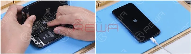
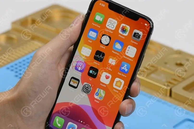
    Premi il pulsante di accensione. Il telefono non si accende.
    Come risolvere l'iPhone 11 che non si accende con una corrente elevata

    Smonta e prova

    Poi smontiamo il telefono e testiamo.

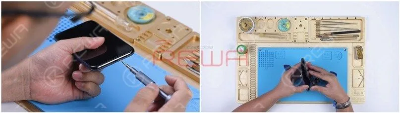
    Rimuovere le due viti pentalobe sul bordo inferiore.

    Tira la piccola sporgenza sulla ventosa per sollevare lo schermo.

    Inserisci una graffa quando c'è uno spazio e falla scorrere lungo lo spazio.
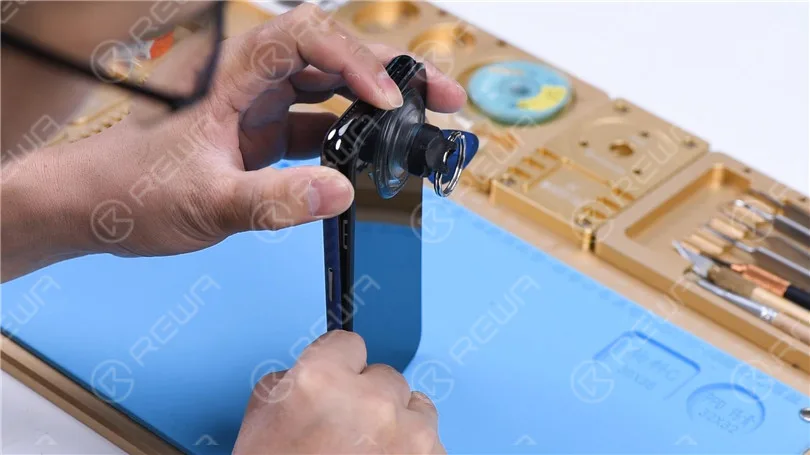
    Come risolvere l'iPhone 11 che non si accende con una corrente elevata

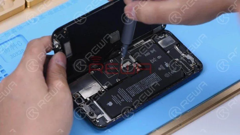
    Dopo aver sollevato lo schermo, rimuovere i coperchi di protezione.

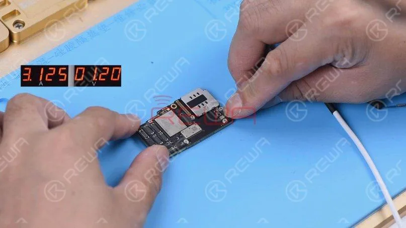
    Scollega la batteria e rimuovi lo schermo. Collega la scheda madre con il cavo di alimentazione.

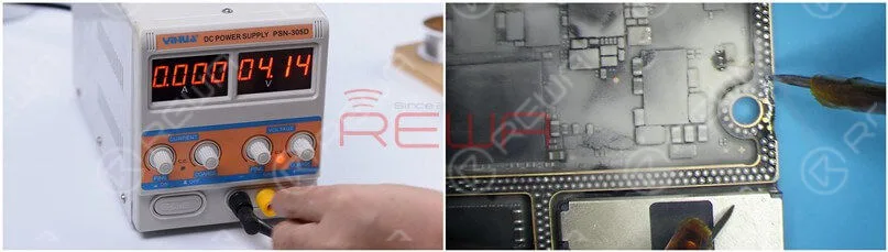
    L'amperometro mostra una corrente elevata di 3,1A.
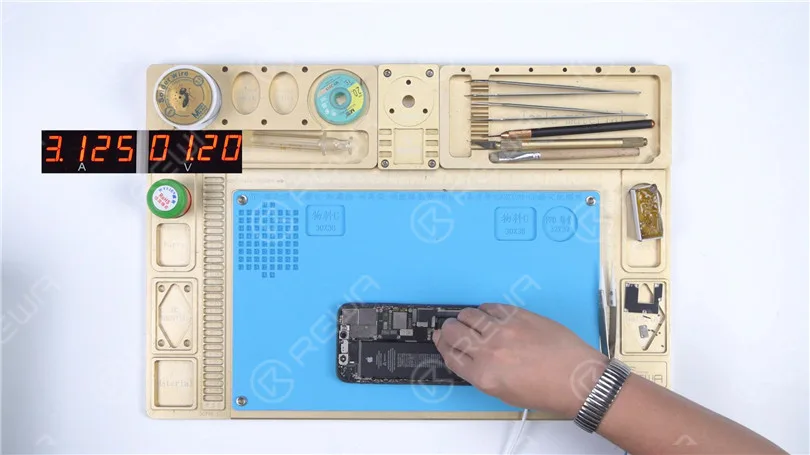
    Come risolvere l'iPhone 11 che non si accende con una corrente elevata

    Scollegare i cavi flessibili. Rimuovere il vassoio della scheda SIM.

    Scollegare la scheda madre. Ricollegare la scheda madre con il cavo di alimentazione.

    L'amperometro mostra ancora una corrente elevata di 3,1 A.

    Indica che la corrente elevata non ha nulla a che fare con altri cavi flessibili.

    Il guasto è sulla scheda madre.
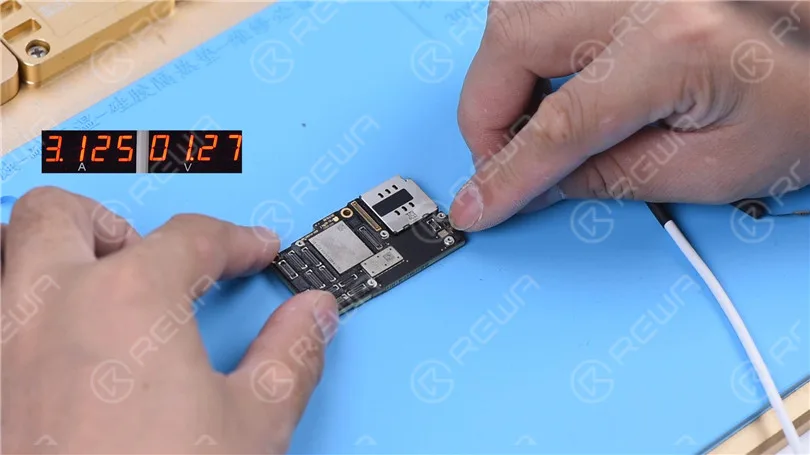
    Come risolvere l'iPhone 11 che non si accende con una corrente elevata

    Misurazione in modalità diodo

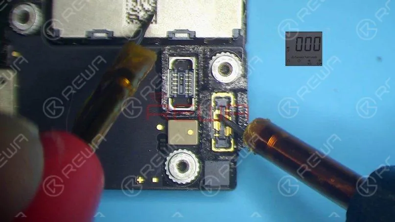
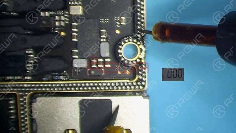
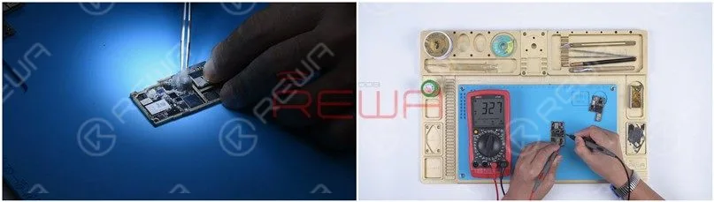
    Esegui misurazione in modalità diodo del pin 1 del J7010 del connettore della batteria.

    Il valore del diodo è 0. Indica che il circuito di alimentazione principale è in corto con la massa.

    Poiché il circuito fornisce contemporaneamente alimentazione alla logic board e alla signal board, dobbiamo separare la motherboard per localizzare il guasto.
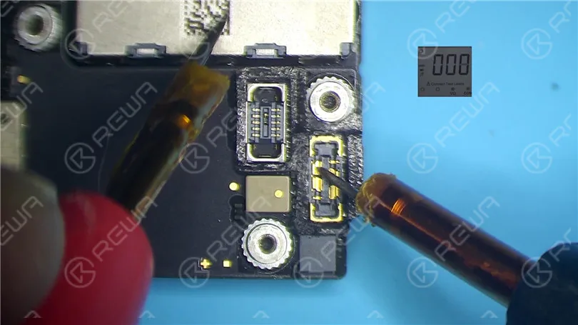
    Come risolvere l'iPhone 11 che non si accende con una corrente elevata

    Separazione della scheda madre

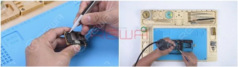
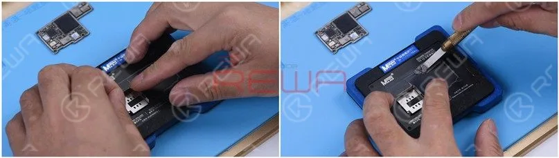
    Rimuovere la schiuma sulla scheda madre.

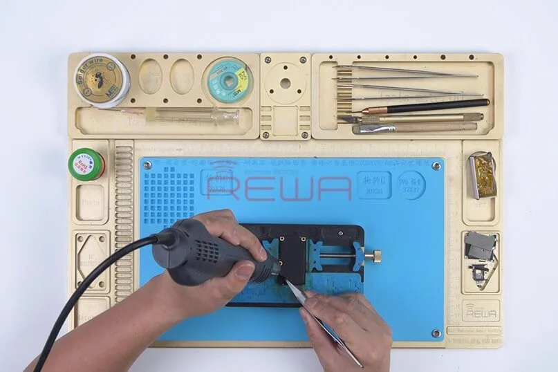
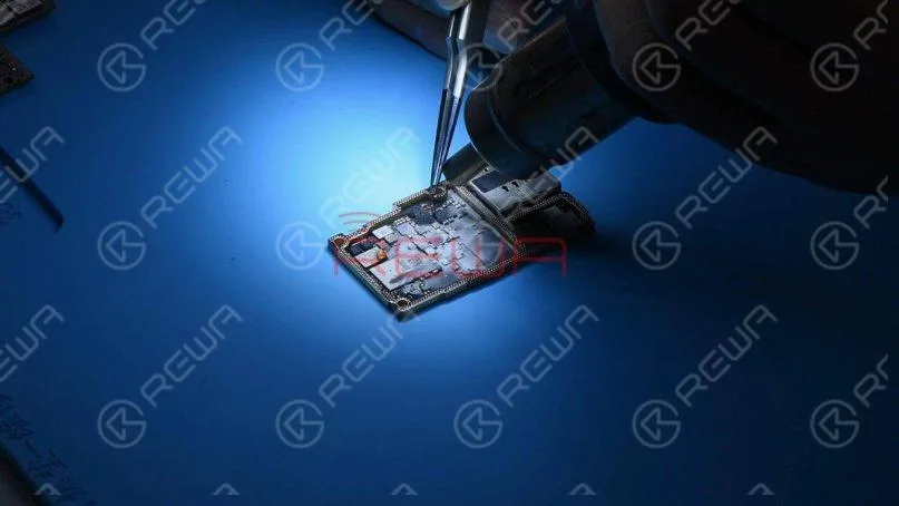
    Scalda il retro della scheda madre con una pistola ad aria calda a 240 gradi Celsius.

    Rimuovere la carta protettiva.

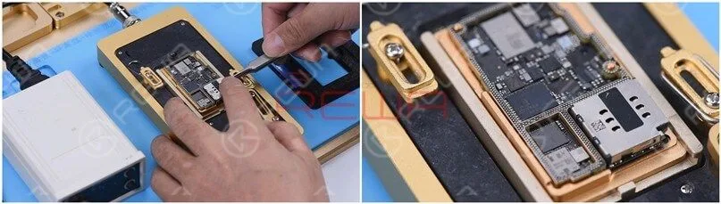
    Metti la scheda madre su Piattaforma di riscaldamento.

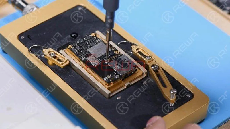
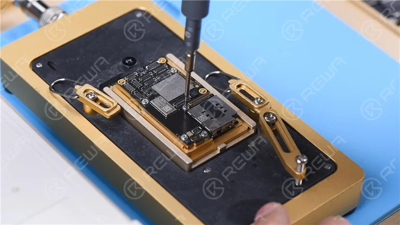
    Per facilitare la rimozione della scheda logica dopo la separazione, avvitare una vite sulla scheda logica.

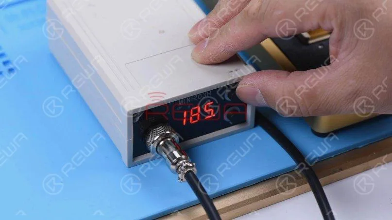
    Imposta la temperatura della piastra riscaldante a 185 gradi Celsius.

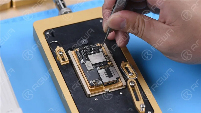
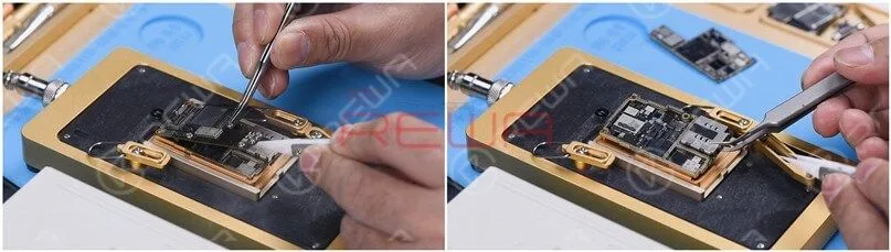
    Bloccare la vite per rimuovere la scheda logica quando la temperatura è salita a 185 gradi Celsius. Rimuovere la scheda del segnale.
    Come risolvere l'iPhone 11 che non si accende con una corrente elevata
    Come risolvere l'iPhone 11 che non si accende con una corrente elevata

    Misurazione in modalità diodo

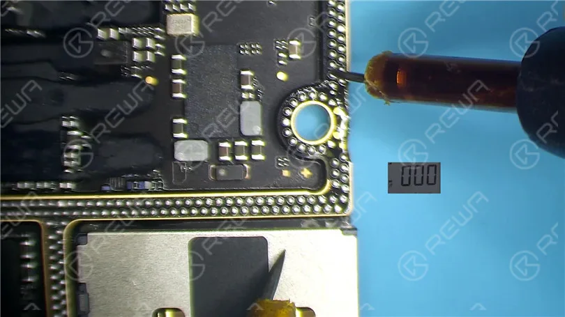
    Esegui la misurazione in modalità diodo del pin 286 sulla scheda del segnale. Il valore del diodo è 0.

    Indica che l'alimentazione principale della scheda del segnale è in corto verso massa.

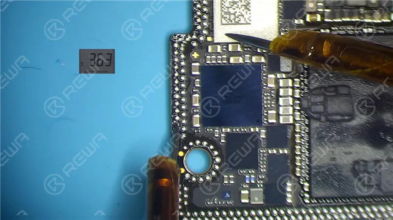
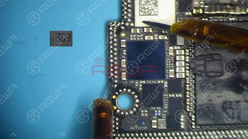
    Misura il pin 286 sulla scheda logica.

    Il valore del diodo è 363, il che significa che la logic board è normale.
    Come risolvere l'iPhone 11 che non si accende con una corrente elevata
    Come risolvere l'iPhone 11 che non si accende con una corrente elevata

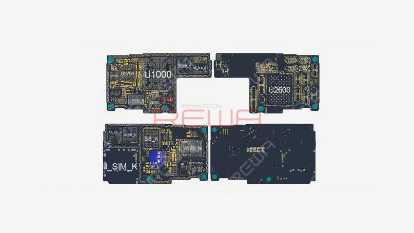
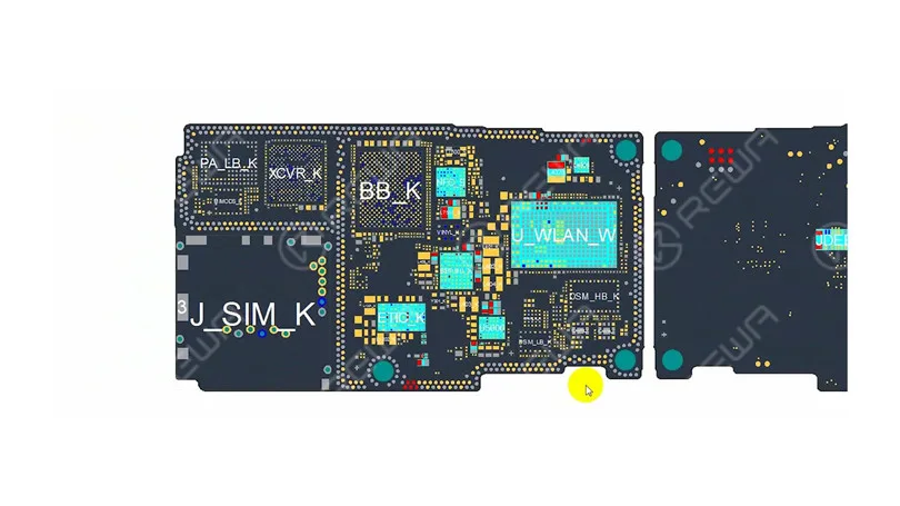
    Apri la bitmap. Possiamo vedere che ci sono molti componenti associati sul circuito dell'alimentatore principale.
    Come risolvere l'iPhone 11 che non si accende con una corrente elevata

    Rilevamento della pece greca

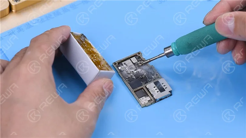
    Successivamente, dobbiamo individuare il componente difettoso con il rilevamento di colofonia.

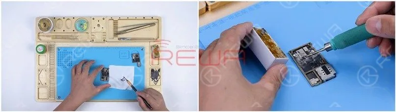
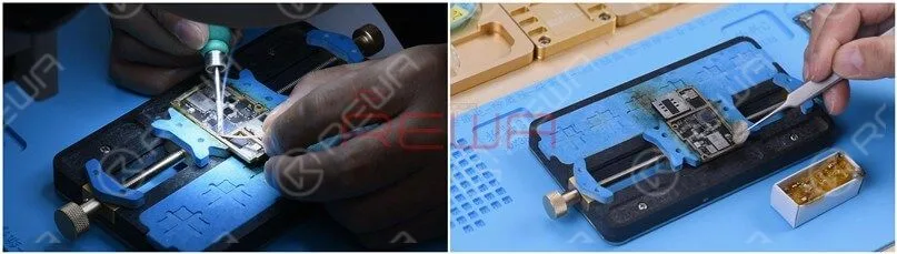
    Rimuovere la pasta termica con un bisturi da scultore.

    Saldare il flussante con un saldatore a 365 gradi Celsius.

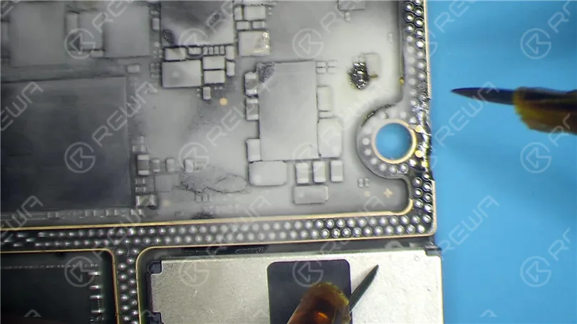
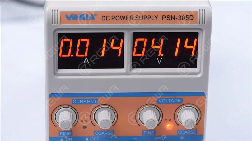
    Fumo resina sulla scheda di segnalazione. Impostare l'alimentazione in corrente continua a 4,1V.

    Collega l'anodo positivo e negativo dell'alimentazione a corrente continua con le sonde del multimetro.

    Collega la sonda nera a massa.

    Collega la sonda rossa al pin 286 sulla scheda del segnale.

    Si può vedere la colofonia sul condensatore C1200 K che si è fusa. Ciò indica che il condensatore è danneggiato.
    Come risolvere l'iPhone 11 che non si accende con una corrente elevata
    Come risolvere l'iPhone 11 che non si accende con una corrente elevata

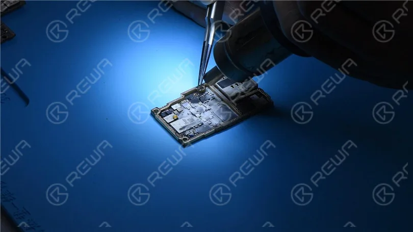
    Poi scaldiamo con la pistola ad aria calda a 350 gradi Celsius. Rimuovere il condensatore con una pinzetta.
    Come risolvere l'iPhone 11 che non si accende con una corrente elevata

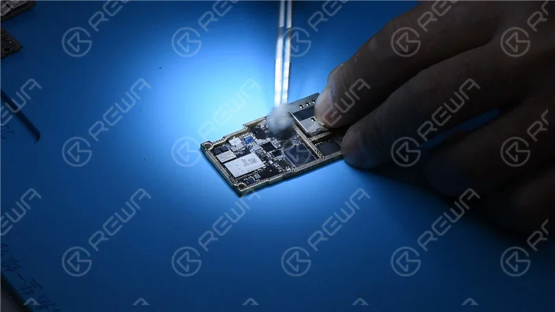
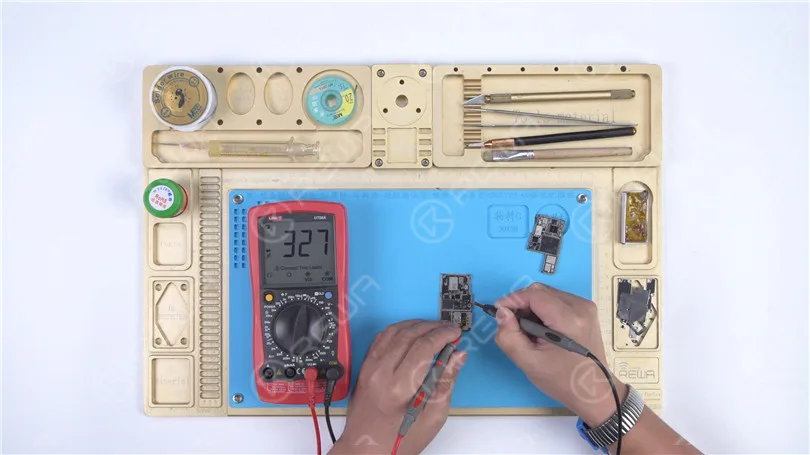
    Pulisci la colofonia sulla scheda del segnale con il pulitore per PCB. Esegui una seconda misurazione in modalità diodo. Il valore del diodo ritorna a un valore normale di 327.
    Come risolvere l'iPhone 11 che non si accende con una corrente elevata
    Come risolvere l'iPhone 11 che non si accende con una corrente elevata

    Ricombinazione della scheda madre

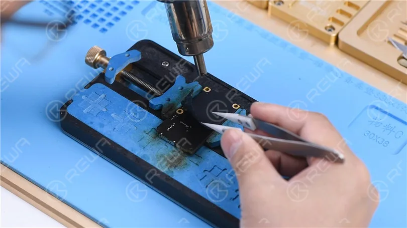
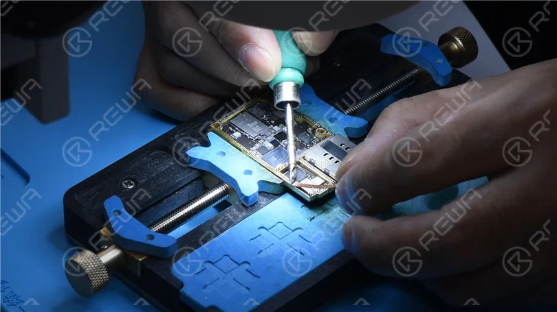
    Spalmare la pece con un saldatore e della treccia dissaldante a 365 gradi Celsius per rimuovere lo stagno sul pad di saldatura.

    Pulisci la scheda del segnale con un pulitore per PCB. Rimuovi lo stagno e pulisci la scheda logica con lo stesso metodo.
    Come risolvere l'iPhone 11 che non si accende con una corrente elevata

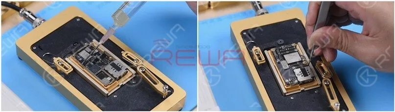
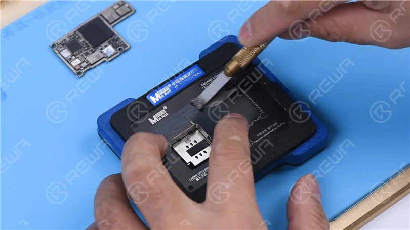
    Attaccare la scheda di segnale alla Piattaforma di Reballing.

    Posizionare la maschera di reballing. Per evitare che la pasta saldante fluisca nelle fessure della scheda madre, inserire una piastra metallica.

    Applicare uno strato di pasta saldante a bassa temperatura.

    Rimuovere la maschera di reballing.
    Come risolvere l'iPhone 11 che non si accende con una corrente elevata

    Posizionare il pannello del segnale sulla piattaforma di riscaldamento a 185 gradi Celsius per riscaldare.

    Dopo che le sfere di saldatura si sono formate, spegni l'alimentazione e raffredda la scheda madre per 5 minuti.

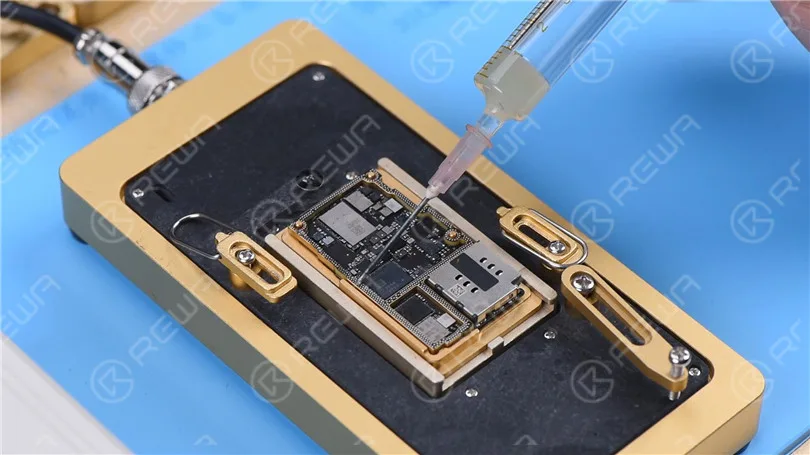
    Applica un po' di pasta flussante.

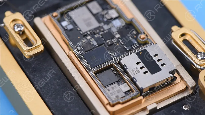
    Allineare la scheda logica con la scheda dei segnali.

    Mantenere il riscaldamento sulla piastra riscaldante a 185 gradi Celsius.

    Quando la temperatura raggiunge i 185 gradi Celsius, continuare a scaldare per 1 minuto.

    Questo passaggio serve a garantire che la scheda logica e la scheda del segnale si adattino perfettamente.
    Come risolvere l'iPhone 11 che non si accende con una corrente elevata
    Come risolvere l'iPhone 11 che non si accende con una corrente elevata
    Come risolvere l'iPhone 11 che non si accende con una corrente elevata

    Test

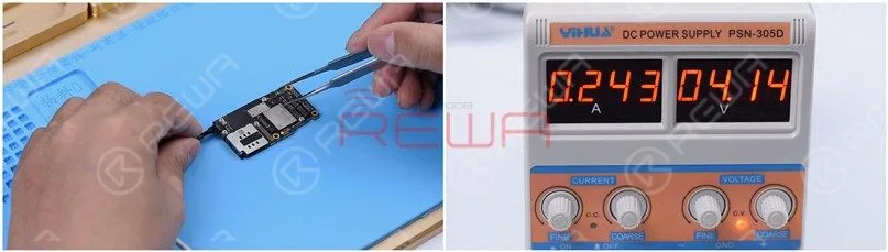
    Collega la scheda madre con il cavo di alimentazione.

    Cortocircuito a massa del pin 12 della J7700. La corrente di avvio diventa normale.

    Metti la scheda madre sul telefono.

    Collega i cavi flessibili. Collega lo schermo e la batteria.

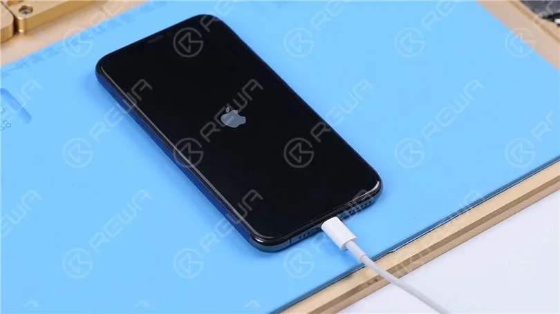
    Perché la batteria è scarica. Collega il cavo di ricarica e il telefono si accende normalmente.
    Come risolvere l'iPhone 11 che non si accende con una corrente elevata
    Come risolvere l'iPhone 11 che non si accende con una corrente elevata
  • How to Fix an iPhone 11 Pro Won’t Turn On

    How to Fix an iPhone 11 Pro Won’t Turn On

    Having trouble with your iPhone 11 Pro refusing to turn on? Don’t worry, we’ve got your back! In this comprehensive guide, we’ll walk you through some practical and effective solutions to fix this frustrating issue.

    Step 1: Disassemble and test

    Remove the two pentalobe screws at the bottom edge and lift the screen.
    Remove the two pentalobe screws at the bottom edge and lift the screen.

    After the screen is lifted, take the shielding covers off, disconnect the battery, and remove the screen.
    After the screen is lifted, take the shielding covers off, disconnect the battery, and remove the screen.

    Connect the motherboard with the Power Cable. The ammeter shows a large current of 3.1A.
    Connect the motherboard with the Power Cable. The ammeter shows a large current of 3.1A.

    Detach the motherboard and connect the motherboard with the Power Cable again. The ammeter still shows a large current of 3.1A.
    Detach the motherboard and connect the motherboard with the Power Cable again. The ammeter still shows a large current of 3.1A.

    It indicates that the large current has nothing to do with other flex cables. The fault is on the motherboard.

    Fase 2: Esecuzione della misura in modalità diodo

    Run diode mode measurement of pin 1 on the J7010 of the battery connector. The diode value is 0 which indicates that the main power supply circuit is shorted to the ground.

    Run diode mode measurement of pin 1 on the J7010 of the battery connector. The diode value is 0 which indicates that the main power supply circuit is shorted to the ground.

    Poiché il circuito fornisce contemporaneamente alimentazione alla logic board e alla signal board, dobbiamo separare la motherboard per localizzare il guasto.

    Fase 3: separazione della scheda madre

    Remove foam on the motherboard. Then heat the back of the motherboard with Pistola ad aria calda at 240℃ to remove the shielding paper.
    Remove foam on the motherboard. Then heat the back of the motherboard with Hot Air Gun at 240℃ to remove the shielding paper.

    Metti la scheda madre su Piattaforma di riscaldamento. To make it easier to remove the logic board after separation, drive a screw on the logic board.
    Put the motherboard on the Heating Platform. To make it easier to remove the logic board after separation, drive a screw on the logic board.

    Set the temperature of the Heating Platform to 185℃.

    Set the temperature of the Heating Platform to 185℃.

    Clamp the screw to remove the logic board when the temperature has risen to 185℃. Lastly, remove the signal board.
    Clamp the screw to remove the logic board when the temperature has risen to 185℃. Lastly, remove the signal board.

    Fase 4: Eseguire nuovamente la misurazione in modalità diodo

    Run diode mode measurement of pin 286 on the signal board. The diode value is 0. It suggests that the main power supply of the signal board is shorted to the ground.

    Run diode mode measurement of pin 286 on the signal board. The diode value is 0. It suggests that the main power supply of the signal board is shorted to the ground.

    Measure pin 286 on the logic board. The diode value is 363 which means the logic board is normal.

    Measure pin 286 on the logic board. The diode value is 363 which means the logic board is normal.

    Open the bitmap. We can see there are many associated components on the main power supply circuit.

    Apri la bitmap. Possiamo vedere che ci sono molti componenti associati sul circuito dell'alimentatore principale.

    Step 5: Rosin detecting to locate the fault

    Next, we need to locate the faulty component with rosin detecting.Remove thermal grease with a Sculpture Knife. Then dip rosin with Saldatore at 365℃ and smoke rosin on the signal board.

    Next, we need to locate the faulty component with rosin detecting.Remove thermal grease with a Sculpture Knife. Then dip rosin with Soldering Iron at 365℃ and smoke rosin on the signal board.

    Set the direct current supply to 4.1V. Connect the positive and negative anode of the direct current supply with multimeter probes. Connect the black probe to the ground and connect the red probe to pin 286 on the signal board. We can see rosin on C1200_K has melted. It indicates that the capacitor is damaged.

    Set the direct current supply to 4.1V. Connect the positive and negative anode of the direct current supply with multimeter probes. Connect the black probe to the ground and connect the red probe to pin 286 on the signal board. We can see rosin on C1200_K has melted. It indicates that the capacitor is damaged.

    Step 6: Eliminate the fault and restore the motherboard

    Then we heat the damaged capacitor with Hot Air Gun at 350℃ and remove it with tweezers.

    Then we heat the damaged capacitor with Hot Air Gun at 350℃ and remove it with tweezers.

    Pulisci la colofonia sulla scheda del segnale con il pulitore per PCB. Esegui una seconda misurazione in modalità diodo. Il valore del diodo ritorna a un valore normale di 327.

    Pulisci la colofonia sulla scheda del segnale con il pulitore per PCB. Esegui una seconda misurazione in modalità diodo. Il valore del diodo ritorna a un valore normale di 327.

    Smear rosin with Soldering Iron and solder wick at 365℃ to remove tin on the bonding pad. Clean the signal board with PCB Cleaner.

    Smear rosin with Soldering Iron and solder wick at 365℃ to remove tin on the bonding pad. Clean the signal board with PCB Cleaner.

    Remove tin and clean the logic board with the same method.Attach the signal board to the Piattaforma di Reballing and put the Reballing Stencil in position. To prevent the solder paste from flowing into the motherboard crevices, insert a metal plate. Apply a layer of low-temperature Pasta saldante. 

    Remove tin and clean the logic board with the same method.Attach the signal board to the Reballing Platform and put the Reballing Stencil in position. To prevent the solder paste from flowing into the motherboard crevices, insert a metal plate. Apply a layer of low-temperature Solder Paste.

    Remove the Reballing Stencil and put the signal board on the Heating Platform at 185℃ to heat. After the solder balls are formed, turn the power off and cool the motherboard for 5 minutes.

    Remove the Reballing Stencil and put the signal board on the Heating Platform at 185℃ to heat. After the solder balls are formed, turn the power off and cool the motherboard for 5 minutes.

    Applicare alcuni Flusso di pasta and align the logic board with the signal board. Keep heating on the Heating Platform at 185℃. When the temperature reaches 185℃, keep heating for 1 minute.This step is to ensure that the logic board and the signal board fit closely.

    Apply some Paste Flux and align the logic board with the signal board. Keep heating on the Heating Platform at 185℃. When the temperature reaches 185℃, keep heating for 1 minute.This step is to ensure that the logic board and the signal board fit closely.Step 7: Test and assemble

    Connect the motherboard with the Power Cable and short to the ground of the J7700 pin 12. The boot current becomes normal.

    Connect the motherboard with the Power Cable and short to the ground of the J7700 pin 12. The boot current becomes normal.

    Put the motherboard on the phone. Connect the flex cables, screen, and battery. Because the battery is dead, plug the charging cable and the phone turns on normally.

    Put the motherboard on the phone. Connect the flex cables, screen, and battery. Because the battery is dead, plug the charging cable and the phone turns on normally.

    Conclusione:

    iPhone 11 Pro won’t turn on with a large current. We found that the main power supply was shorted to the ground through measuring the battery connector. The fault was found to be on the signal board after separation. Rosin detecting showed us that C1200_K was damaged. After removing C1200_K, the fault was cleared.

  • iPhone 11 Pro Motherboard Separation

    iPhone 11 Pro Motherboard Separation

    As we all know, iPhone new series have undergone considerable changes on both inside and outside.

    Especially on the motherboard.

    How will these changes affect the repair industry?

    Will it make third-party repair harder or easier?

    Follow our iPhone 11 Pro motherboard separation & recombination blog today and find the answer by yourself.

    iPhone 11 Pro Motherboard Separation

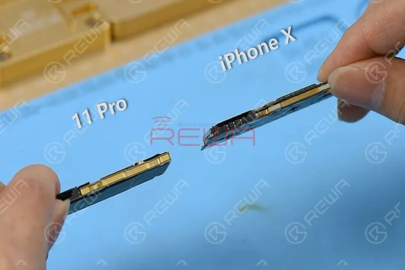
    Compared with iPhone X series, iPhone 11 Pro’s motherboard is smaller with a much denser component array.

    It is also thicker.

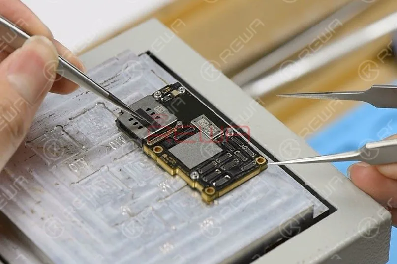
    There are layers of graphite thermal transfer material on the backside.

    It can dissipate heat generated from the motherboard efficiently.
    Compared with iPhone X series, iPhone 11 Pro’s motherboard is smaller with a much denser component array. It is also thicker. There are layers of graphite thermal transfer material on the backside. It can dissipate heat generated from the motherboard efficiently.

    Passo 1

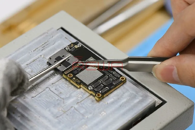
    Remove the graphite thermal transfer material with tweezers first.

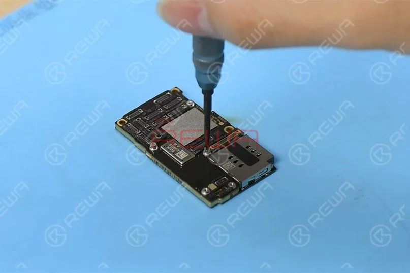
    To recombine the two layers without reballing after separation, let’s fit two screws into the screw holes reserved on the motherboard.

    Remove the graphite thermal transfer material with tweezers first. To recombine the two layers without reballing after separation, let’s fit two screws into the screw holes reserved on the motherboard.

    Passo 2

    Set temperature of the heating platform at 170℃.

    With temperature of the platform reaching 170℃, place the motherboard on the platform to heat for 3 minutes.

    Press the SIM card reader with the tweezers and push the upper layer with another tweezers slightly.
    Set temperature of the heating platform at 170℃. With temperature of the platform reaching 170℃, place the motherboard on the platform to heat for 3 minutes. Press the SIM card reader with the tweezers and push the upper layer with another tweezers slightly.

    Passo 3

    With solder balls on the third space PCB starting to melt, clamp the screws fitted into the screw holes with tweezers and pick up the upper layer with tweezers vertically.

    Tips: do not shake the tweezers when picking up the upper layer.

    The third space PCB might be stuck in bridging issues and the recombination work would also be affected.

    Continue to pick up the lower layer.

    iPhone 11 Pro Motherboard Structure

    Now let’s start with the structure of the motherboard.

    The Upper Layer

    iPhone 11 Pro Motherboard Structure

    A.Thermal Compound

    CPU and areas around CPU are covered with a large amount of thermal compound to dissipate heat generated from A13 CPU.

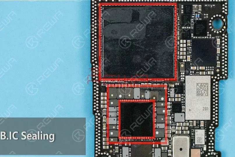
    B.IC Sealing

    CPU, PMU, and inductors around PMU are sealed with adhesive adding to the difficulty of repairs to some extent.

    C.Dense Component Array Around PMU

    Professional handwork is required when soldering/desoldering PMU.

    D.IC USB

    Unlike iPhone X series, the USB IC of iPhone 11 Pro hasn’t been sealed with adhesive, and it is far from CPU.

    Therefore, the difficulty of USB IC relevant repairs is relatively reduced

    Unlike iPhone X series, the A13 CPU of iPhone 11 Pro is not located right on the backside of the NAND flash chip.

    This can reduce the bridging possibility of CPU when soldering/desoldering the NAND flash chip.

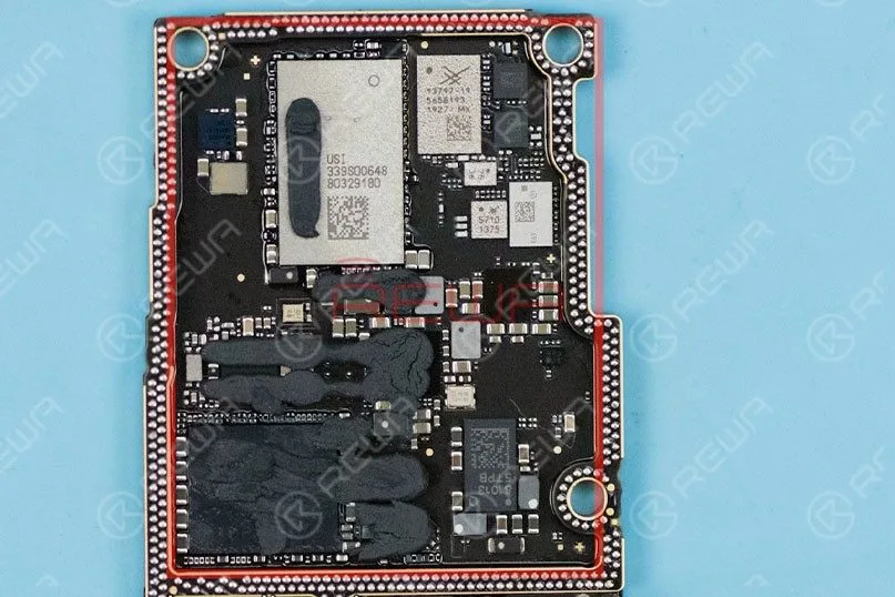
    The Lower Layer

    The Lower Layer

    A. Different from iPhone X series, the lower layer of iPhone 11 Pro has a dispersive component array. Therefore, the difficulty of signal relevant repairs is also reduced.

    B. Unlike iPhone X series, the SIM card reader of iPhone 11 Pro is independent from other components. We don’t have to remove the SIM card reader when working on signal relevant repairs.

    iPhone 11 Pro Motherboard Recombination Without Reballing

    Set temperature of the heating platform at 170℃.

    With temperature of the platform reaching 170℃, place the lower layer on the platform to heat for 10 seconds.

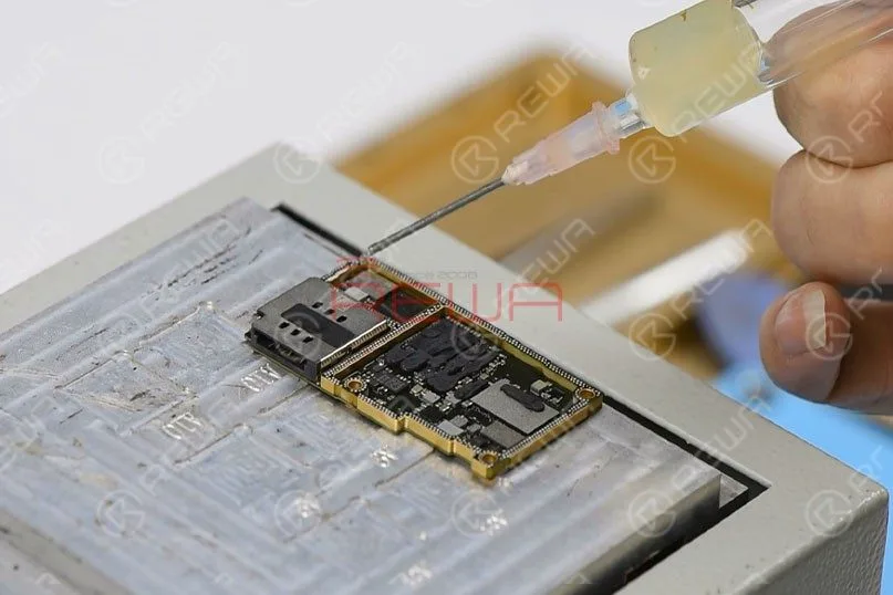
    Apply some Paste Flux to the third space PCB evenly.

    Get the upper layer in position and heat for about 5 minutes.
    Set temperature of the heating platform at 170℃. With temperature of the platform reaching 170℃, place the lower layer on the platform to heat for 10 seconds. Apply some Paste Flux to the third space PCB evenly. Get the upper layer in position and heat for about 5 minutes.

    Then, press the SIM card reader with the tweezers and push the upper layer with another tweezers slightly.

    If the upper layer returns to the previous position automatically, then the soldering process is completed.

    Test

    Ora possiamo assemblare il telefono e testare.

    Test    Now we can assemble the phone and test.

    Get the motherboard and display assembly installed and get the battery connected.

    Premi il pulsante di accensione per accendere il telefono.

    Il telefono si accende normalmente.
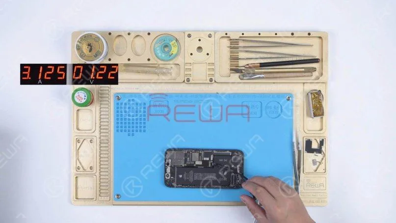
    Run function test. All going well.

    Sintesi

    The separation&recombination of the motherboard of iPhone 11 Pro shows that the motherboard is smaller and more squared.

    Compared with the iPhone X series, it will not be easily damaged by external forces.

    The high integration of the motherboard also means that more professional handwork is required.

    Overall, the difficulty of iPhone 11 Pro motherboard repairs is reduced.

    Strumenti e parti di ricambio

    Potete anche visitare Canale Youtube REWA to check our video of iPhone 11 Pro Motherboard Separation And Recombination.

  • Riparazione del vetro posteriore di iPhone 11 Pro

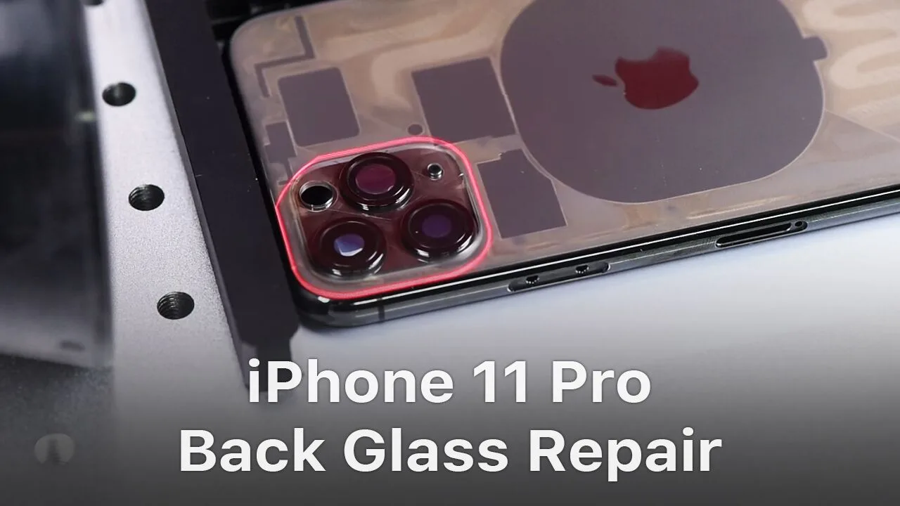
    Riparazione del vetro posteriore di iPhone 11 Pro

    È l'iPhone più potente e più avanzato che Apple abbia mai costruito, iPhone 11 Pro  è realizzato in acciaio inossidabile di grado chirurgico e il retro è un unico pezzo di vetro macchina con rivestimento ottico PVD, che aumenta la difficoltà di riparazione.

    Inoltre, la disposizione delle fotocamere posteriori dell'iPhone 11 Pro aumenta notevolmente la difficoltà di riparazione del vetro posteriore.

    REWA LAB ha provato diverse soluzioni (riscaldamento con la pistola ad aria calda, separazione con il disperdente/assistenza al congelamento), ma non siamo riusciti a rimuovere il vetro intorno alla telecamera a tre lenti in modo sicuro ed efficiente.

    Controllate la nostra operazione dettagliata sulla riparazione del vetro posteriore dell'iPhone 11 Pro e speriamo di potervi illuminare in qualche modo.

    Scansione del vetro posteriore di 11 Pro con il laser

    Prima di tutto, posizionare il vetro posteriore dell'iPhone 11 Pro sotto la sonda per la messa a fuoco.

    Quindi posizionare il vetro posteriore dell'iPhone 11 Pro sul pannello operativo.

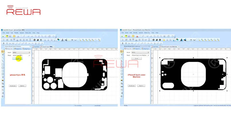
    Scegliere "iPhone 11 Pro" dall'elenco dei modelli e fare clic su "Carica" per caricare il disegno.

    L'area nera del disegno è l'area da scansionare, mentre l'area bianca è l'area da conservare.

    Suggerimenti: Confrontando i due disegni si può notare che, a differenza dell'iPhone X, ci sono più aree da cui il laser deve tenersi lontano durante la scansione dell'iPhone 11 Pro.
    Innanzitutto, posizionare il vetro posteriore dell'iPhone 11 Pro sotto la sonda per la messa a fuoco. Quindi posizionare il vetro posteriore dell'iPhone 11 Pro sul pannello operativo.   Scegliere "iPhone 11 Pro" dall'elenco dei modelli e fare clic su "Carica" per caricare il disegno.   L'area nera del disegno è l'area da scansionare, mentre l'area bianca è l'area da conservare.   Suggerimenti: Confrontando i due disegni si può notare che, a differenza dell'iPhone X, ci sono più aree da cui il laser deve tenersi lontano durante la scansione dell'iPhone 11 Pro.

    Dopo aver caricato il disegno dell'iPhone 11 Pro, regolare l'area di scansione della luce laser sul vetro posteriore.

    Una volta terminato, impostare i parametri e fare clic su 'Mark' per scansionare il vetro posteriore con la luce laser.

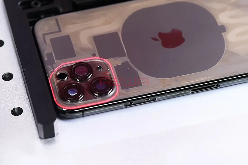
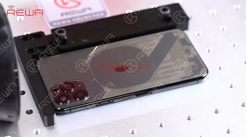
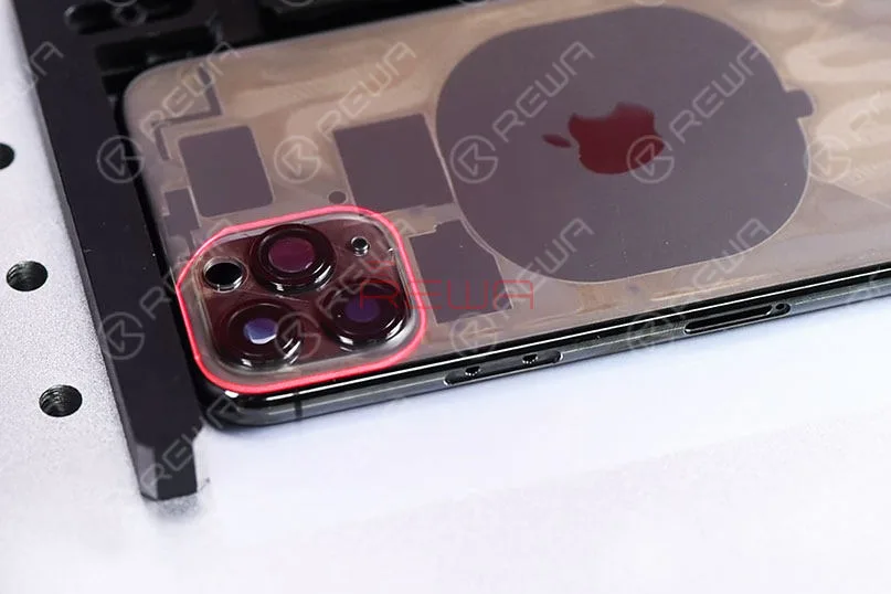
    Il vetro posteriore diventa trasparente dopo la scansione laser.
    Dopo aver caricato il disegno dell'iPhone 11 Pro, regolare l'area di scansione della luce laser sul vetro posteriore. Al termine, impostare i parametri e fare clic su 'Mark' per eseguire la scansione del vetro posteriore con la luce laser. Il vetro posteriore diventa trasparente dopo la scansione laser.

    Scansione del vetro intorno alla fotocamera a tre lenti con il laser

    Come si può notare, il vetro intorno alla fotocamera a tre lenti è relativamente spesso.

    La scansione a luce laser non ha funzionato bene con l'area in questione.

    Dopo diversi tentativi ed esperimenti, REWA LAB ha completato con successo un disegno specializzato per l'area della fotocamera a tre lenti.

    Scansionare nuovamente l'area della telecamera a tre lenti con il laser con l'aiuto del disegno.

    Anche il vetro intorno alla telecamera a tre lenti diventa trasparente dopo la seconda scansione laser.
    Eseguire nuovamente la scansione laser dell'area della telecamera a tre lenti con l'aiuto del disegno. Anche il vetro intorno alla telecamera a tre lenti diventa trasparente dopo la seconda scansione laser.

    Separare il vetro posteriore dal telaio centrale 

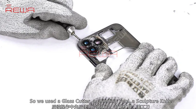
    Ora è necessario separare il vetro posteriore dal fotogramma centrale. Il vetro posteriore scansionato può essere separato facilmente. Tuttavia, il vetro intorno alla fotocamera a tre lenti richiede un'ulteriore operazione. Gli strumenti comunemente utilizzati non sono riusciti a rimuovere il vetro, quindi abbiamo utilizzato un tagliavetro, un utensile per smerigliare, un coltello per sculture e un tronchesino per rimuovere il vetro intorno alla fotocamera a tre lenti. Infine, una volta completato, rimuovere l'adesivo nero residuo con la macchina laser.
    Ora è necessario separare il vetro posteriore dal fotogramma centrale. Il vetro posteriore scansionato può essere separato facilmente. Tuttavia, il vetro intorno alla fotocamera a tre lenti richiede un'ulteriore operazione. Gli strumenti comunemente utilizzati non sono riusciti a rimuovere il vetro, quindi abbiamo utilizzato un tagliavetro, un utensile per smerigliare, un coltello per sculture e un tronchesino per rimuovere il vetro intorno alla fotocamera a tre lenti. Infine, una volta completato, rimuovere l'adesivo nero residuo con la macchina laser.

    L'anello del supporto della fotocamera dell'iPhone 11 è più duro e presenta pareti interne spesse, il che aumenta la difficoltà di lucidatura.

    Nel frattempo, anche l'obiettivo della fotocamera può essere facilmente danneggiato durante la lucidatura.

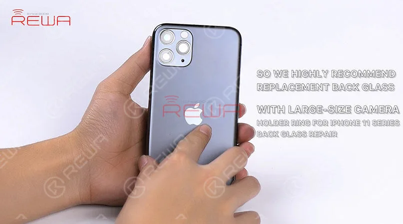
    Per questo motivo consigliamo vivamente di sostituire il vetro posteriore con un grande foro per la fotocamera per la riparazione del vetro posteriore dell'iPhone 11 Series.
    L'anello del supporto della fotocamera dell'iPhone 11 è più duro e dotato di pareti interne spesse, il che rende ancora più difficile la lucidatura. Nel frattempo, anche l'obiettivo della fotocamera può essere facilmente danneggiato durante la lucidatura. Per questo motivo, consigliamo vivamente di sostituire il vetro posteriore con un grande foro per la fotocamera per la riparazione del vetro posteriore dell'iPhone 11 Series.

    A causa della particolare disposizione delle tre fotocamere dell'iPhone 11 Pro, anche lo spazio tra le tre fotocamere è stretto e ciò aumenta la difficoltà di separazione del vetro posteriore.

    Pertanto, la macchina laser può essere la soluzione più sicura ed efficiente per la riparazione del vetro posteriore dell'iPhone 11 Pro.

    Per maggiori dettagli sulla riparazione del vetro posteriore dell'iPhone 11 Pro, guardate il video qui sotto. Potete anche visitare Canale YouTube REWA per altri video sulla serie iPhone 11.

    REWA LAB lavorerà duramente per fornire una soluzione migliore per la riparazione del vetro posteriore di iPhone 11 Pro.

    Anche le parti di ricambio della serie iPhone 11 sono in arrivo, rimanete sintonizzati su Negozio online REWA.

  • Riparazione del vetro posteriore di iPhone 11 Pro

    Riparazione del vetro posteriore di iPhone 11 Pro

    Rear cameras of iPhone 11 series greatly increase the difficulty of back glass repair. REWA LAB tried different solutions (heating with the Hot Air Gun, separating with the dispergator/freeze assistance) and we were unable to remove the glass around the triple-lens camera safely and efficiently. Check our iPhone 11 Pro back glass repair video now and hope we can enlighten you somehow. Please let us know your thoughts on this topic in the comment below.

    Tools & Parts used in this iPhone 11 Pro Back Glass Refurbishing video:


  • Turn iPhone 11 Pro Into iPhone 11 Pro Max

    Turn iPhone 11 Pro Into iPhone 11 Pro Max

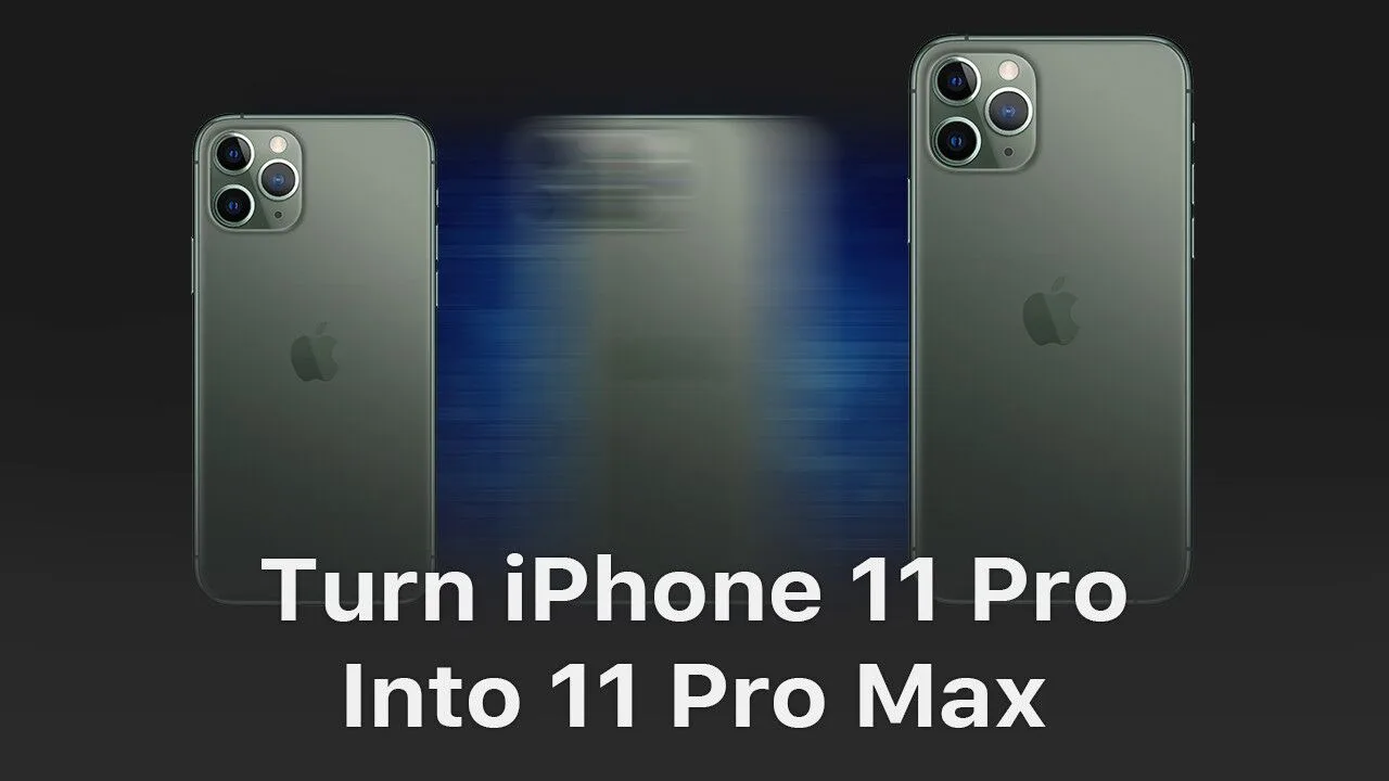
    Can iPhone 11 Pro possibly be turned into iPhone 11 Pro Max? It is actually theoretically possible. With pins of the two phones’ display connector and touch connector functioning almost the same, we can turn an iPhone 11 Pro into an iPhone 11 Pro Max by changing board ID resistors. Check our video now and find out how we finally made it.

    Warm Tips: This video is made for technique sharing only. For those who have no professional skills, please look before you leap.

    Tools & Parts used to separate iPhone 11 Pro:

  • iPhone 11 Pro Motherboard Separating & Recombination

    iPhone 11 Pro Motherboard Separating & Recombination

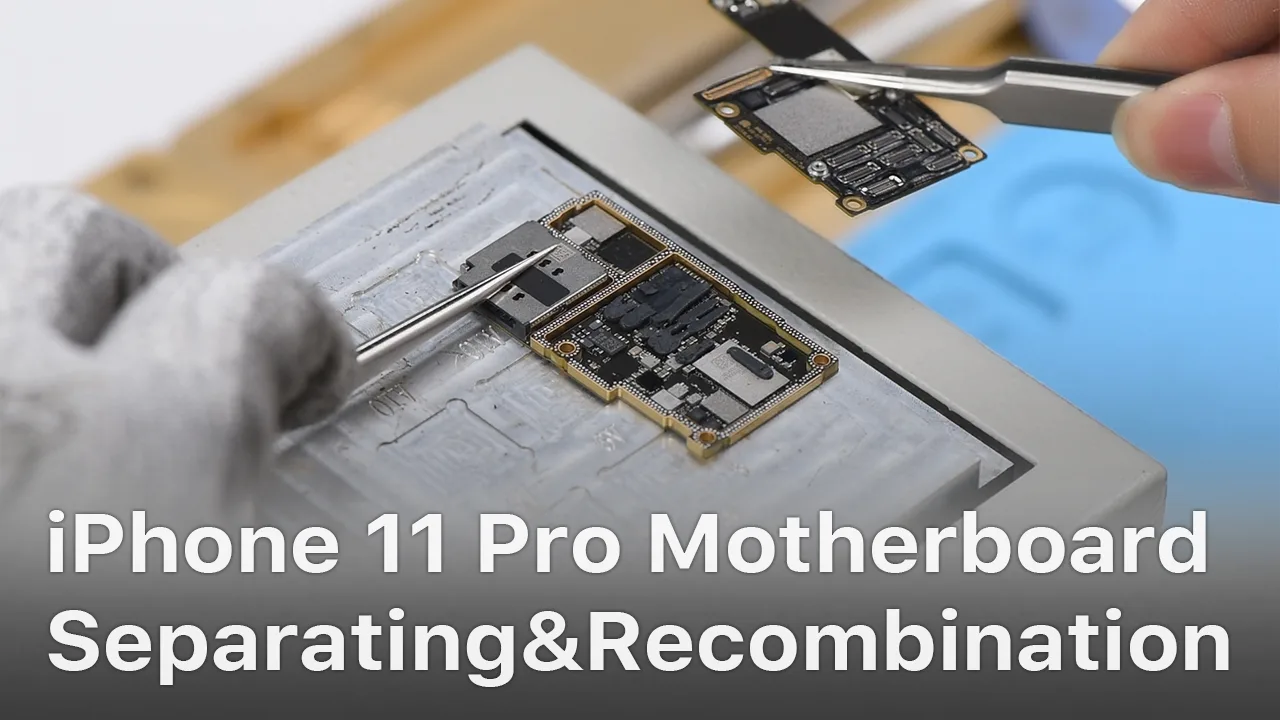
    iPhone new series have undergone considerable changes on both inside and outside. Especially on the motherboard. How will these changes affect the repair industry? Will it make third-party repair harder or easier? Follow our iPhone 11 Pro motherboard separation&recombination video today and find the answer by yourself.

    Tools & Parts used to separate iPhone 11 Pro: