Tag: iPhone 11 Pro Max

  • iPhone 11 Pro Max schermo nero e nessun problema di avvio riparazione

    iPhone 11 Pro Max schermo nero e nessun problema di avvio riparazione

    The iPhone 11 Pro Max is a powerful device, but even the best smartphones can run into issues. One common problem is when the screen suddenly turns black, and the phone refuses to boot. In this guide, we’ll take you through the step-by-step process of diagnosing and repairing this issue. Whether you’re a professional technician or a DIY repair enthusiast, this article will help you troubleshoot and resolve the no-boot problem on your iPhone 11 Pro Max.
    iPhone 11 Pro Max

    Dettagli telefonici

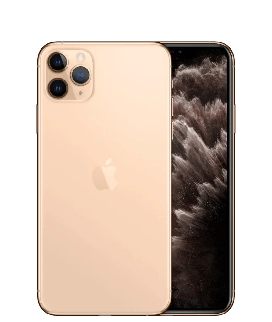
    Modello: iPhone 11 Pro Max

    Annunciato: 2019, September 10

    Fenomeno dei difetti

    The iPhone 11 Pro Max suddenly experienced a black screen and could not boot during regular use.

    Risoluzione dei problemi

    1: Valutazione iniziale
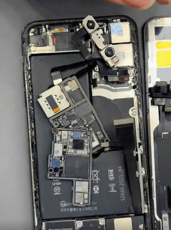
    iphone 11 pro max black screen no boot issue repair cannot start up
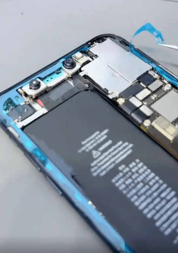
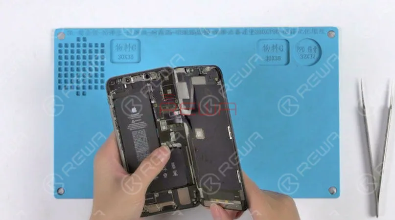
    • The phone was previously repaired by another technician. Upon receiving it, the motherboard was already separated. A visual inspection revealed no signs of physical damage or water exposure.

    2: Testing the Motherboard
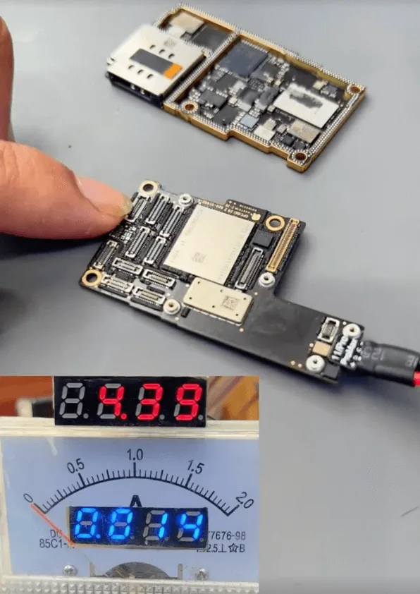
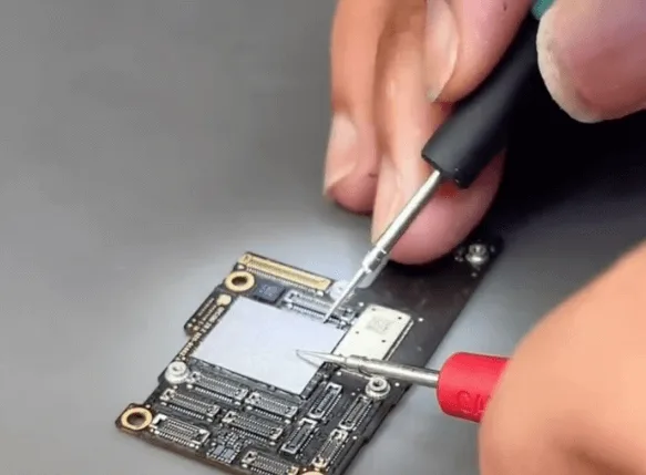
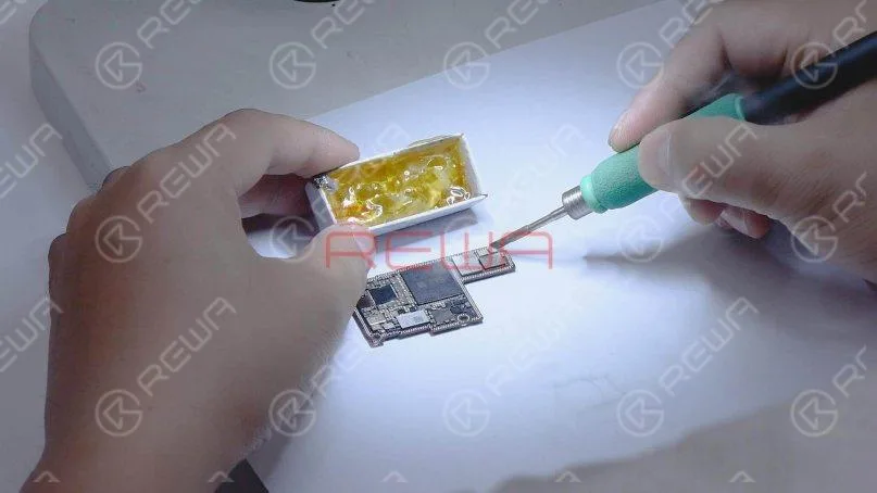
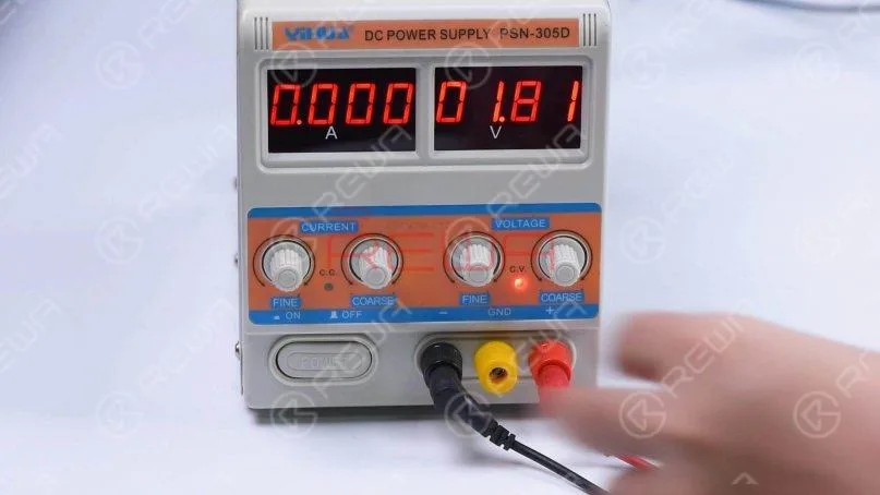
    • Connect the upper layer of the motherboard to a DC power supply and attempt to trigger the boot process using tweezers.
    • The boot current is fixed at 14mA, which suggests a problem with the NAND chip or CPU, particularly with the power supply rails.

    3: Diagnosing the Power Supply Issue
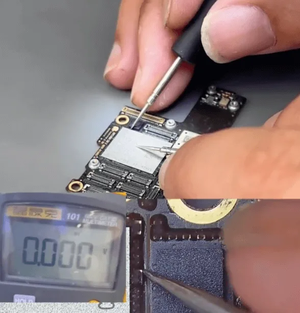
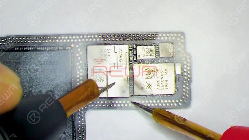
    • Use a multimeter to check the power supply rails associated with the NAND chip and CPU.
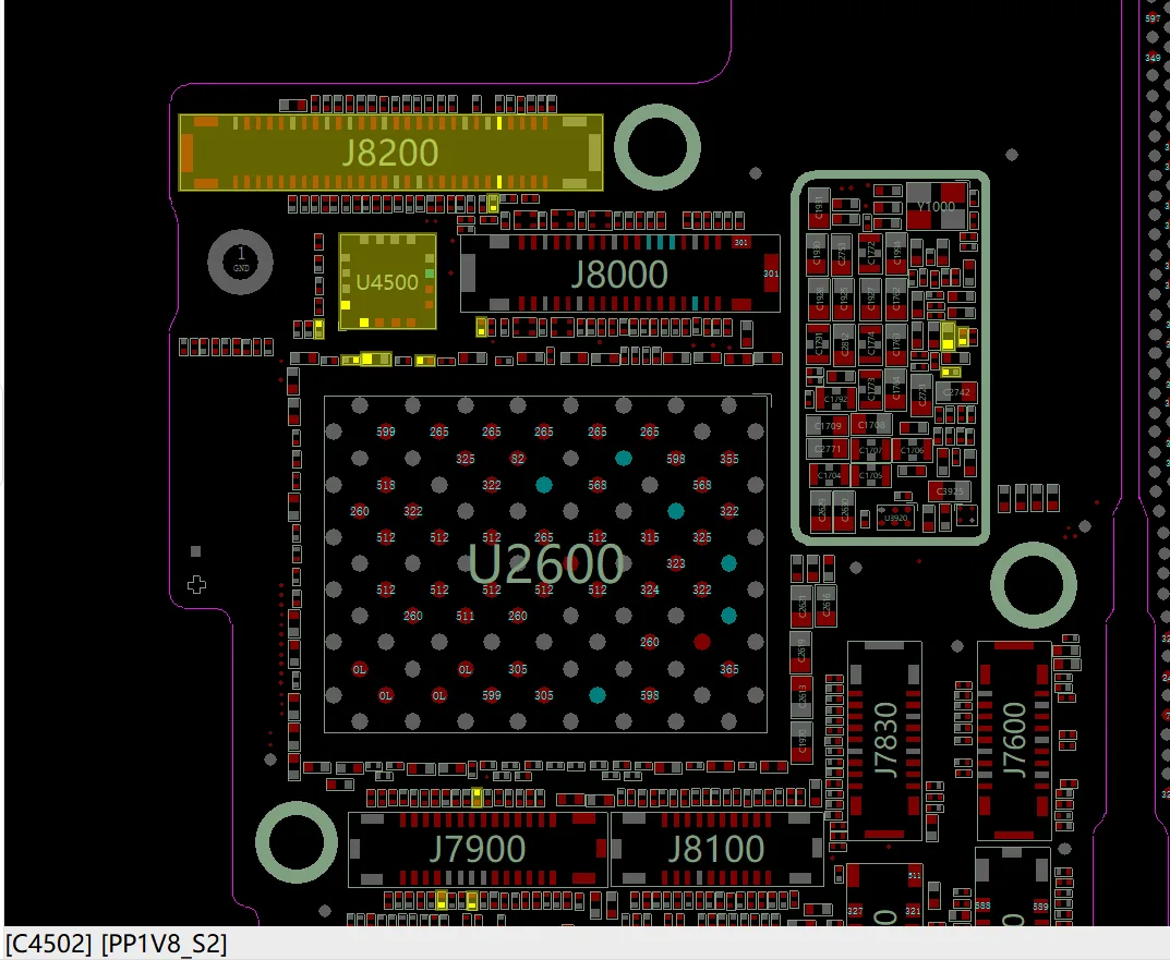
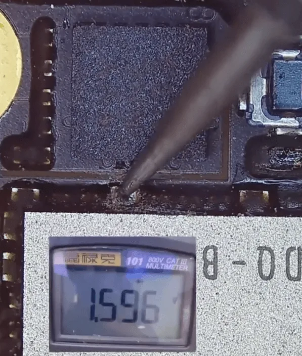
    • After carefully checking the small capacitors around the NAND chip, one rail shows a short circuit. The affected rail is the 1.8V power supply rail (PP1V8_S2) for the NAND.

    Processo di riparazione

    1: Removing the Shorted Capacitor
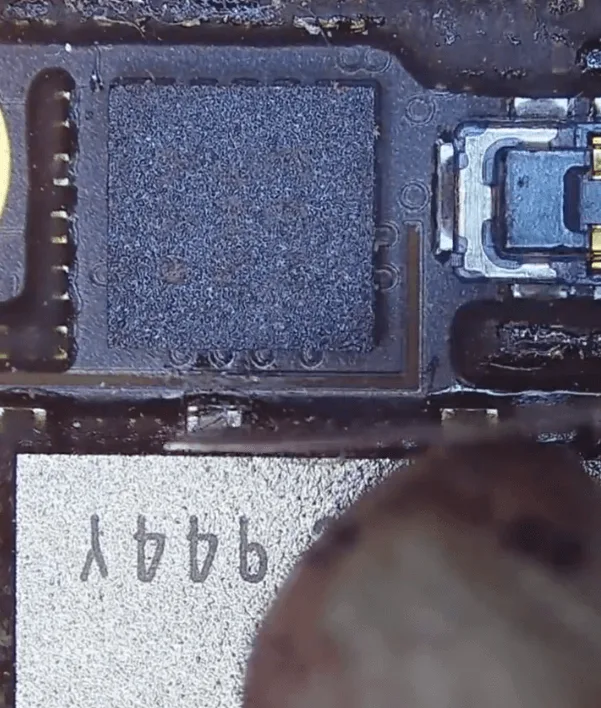
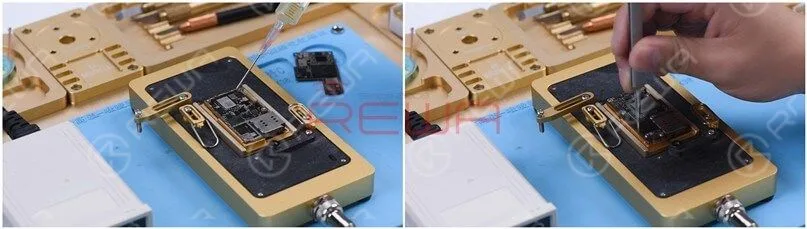
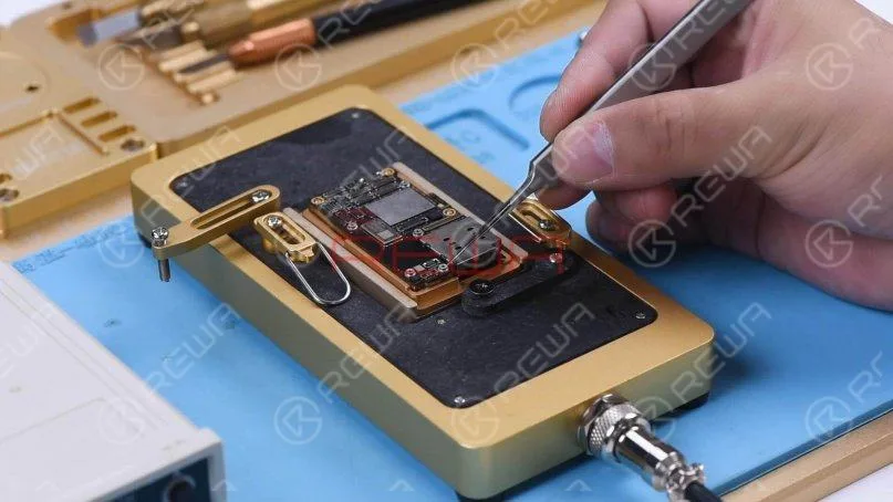
    • Carefully remove the black glue covering the NAND chip using a hot air gun and a blade knife.
    • Identify and remove the shorted capacitor, which is a filter-type capacitor. Since it’s a filter capacitor, it can be safely removed without replacement.

    Recheck the diode value on the rail after removing the capacitor, and confirm that it has returned to normal.

    2: Reassembling the Motherboard
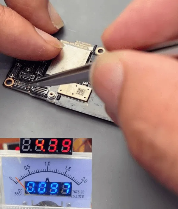
    • Connect the motherboard to the DC power supply and trigger the boot process again. This time, the boot current returns to normal.
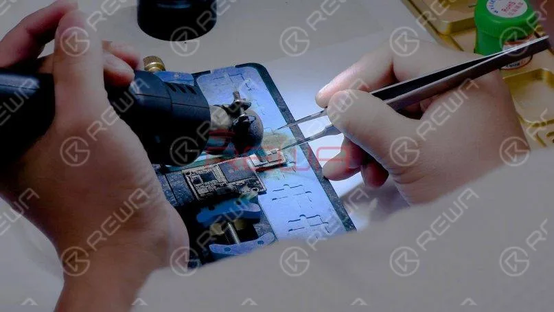
    • Recombine the two layers of the motherboard using a hot air gun, ensuring a proper fit.

    3: Final Assembly and Testing
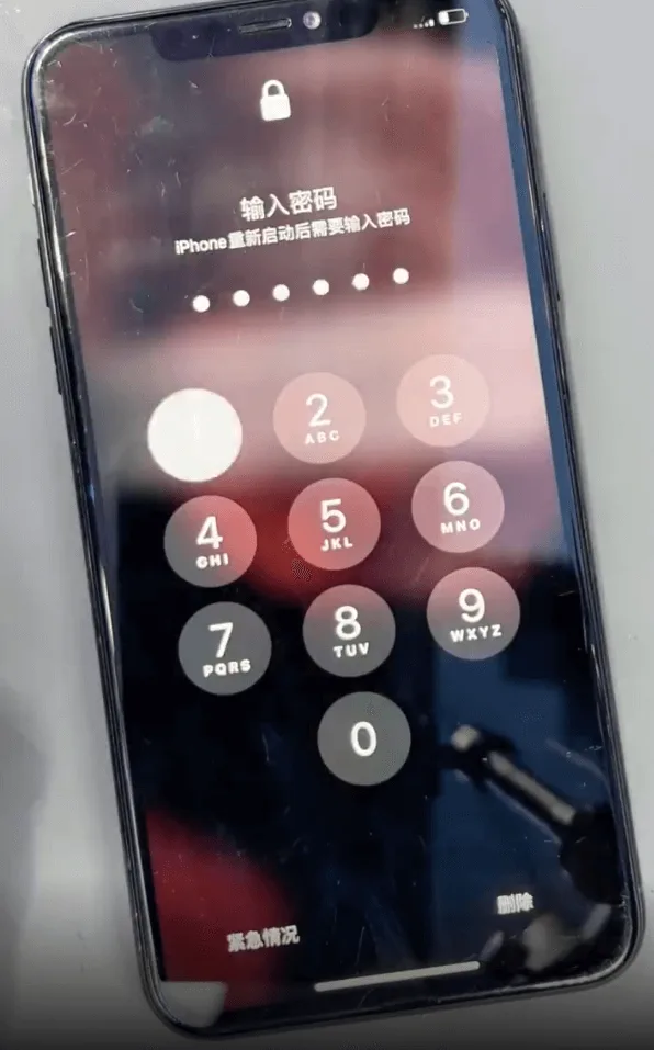
    iphone 11 pro max black screen no boot issue repair phone can be booted
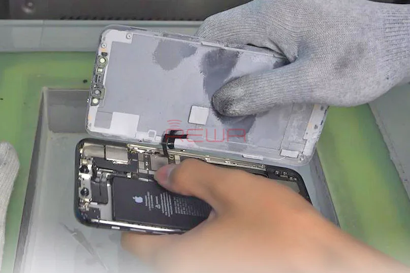
    • Reassemble the motherboard with the housing and other parts, taking care to install the waterproof seal sticker.
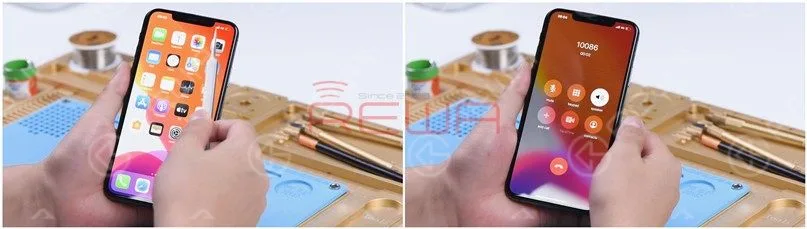
    • Assemble the screen and press the power button to conduct a final test.
    • After testing, all functions of the phone are working correctly. The no-boot issue has been successfully resolved by removing the shorted filter-type capacitor.

    Conclusione:

    Repairing an iPhone 11 Pro Max that won’t boot due to a black screen can be a challenging task, but by following a systematic approach, the issue can be identified and resolved. In this case, removing a shorted capacitor from the NAND power supply rail restored the device to full functionality. For those facing similar issues, this guide provides a clear path to bring your device back to life. Stay tuned for more detailed repair guides to help you tackle even the most complex smartphone issues.
  • Risoluzione dei problemi di iPhone 11 Pro Max senza servizio

    Risoluzione dei problemi di iPhone 11 Pro Max senza servizio

    Recently, many repair technicians reported that they had received lots of iPhone 11 Pro Max with no service.

    Worse still, the fault could not be eliminated after replacing the signal board.

    Based on experience, REWA LAB technicians preliminarily conclude that the fault is likely on the signal pads of the logic board. Let’s check it out!

    Step 1: Fault analysis

    The motherboard has been repaired once.

    The original fault was no service but with the baseband modem firmware.

    The previous repair welded the baseband CPU and baseband EPROM to a good signal board.

    But the phone still had no service. It can be preliminarily judged that there are two possible faults.

    One is the damage of baseband CPU and baseband EPROM.

    The other is the damage of circuits related to the signal on the logic board.

    First of all, we install the motherboard on the phone to test.

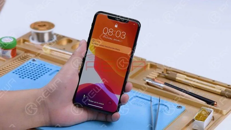
    The phone turns on normally but has no service.
    First of all, we install the motherboard on the phone to test. The phone turns on normally but has no service.

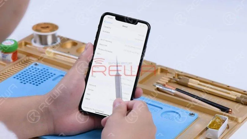
    Go to Settings, General, and About. We can see that the phone has no modem firmware.
    Go to Settings, General, and About. We can see that the phone has no modem firmware.

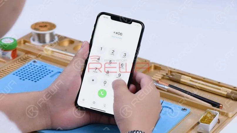
    Dial *#06# and the IMEI can’t be seen.

    Dial *#06# and the IMEI can’t be seen.

    The phone used to have modem firmware but now no longer has it. The cause may be related to pseudo soldering of the motherboard middle layer or damage of the baseband CPU and baseband EPROM.

    Step 2: Motherboard separation and troubleshooting

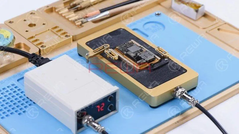
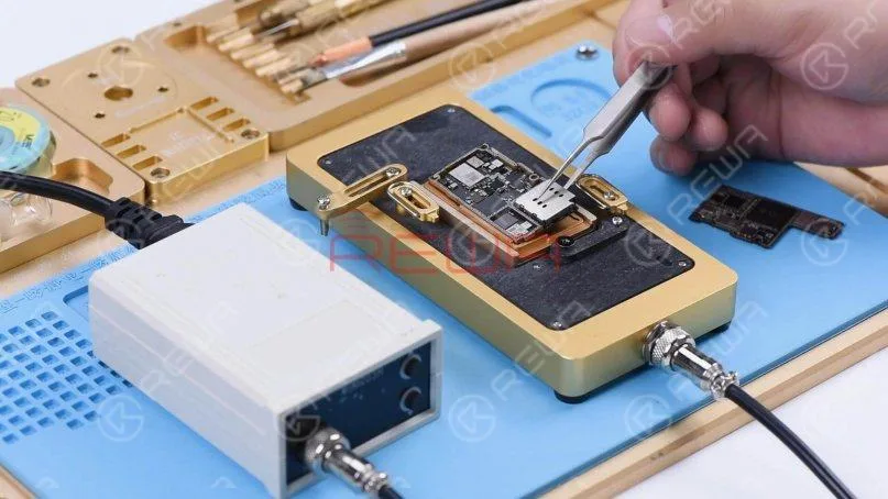
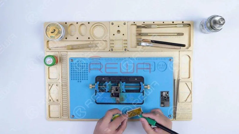
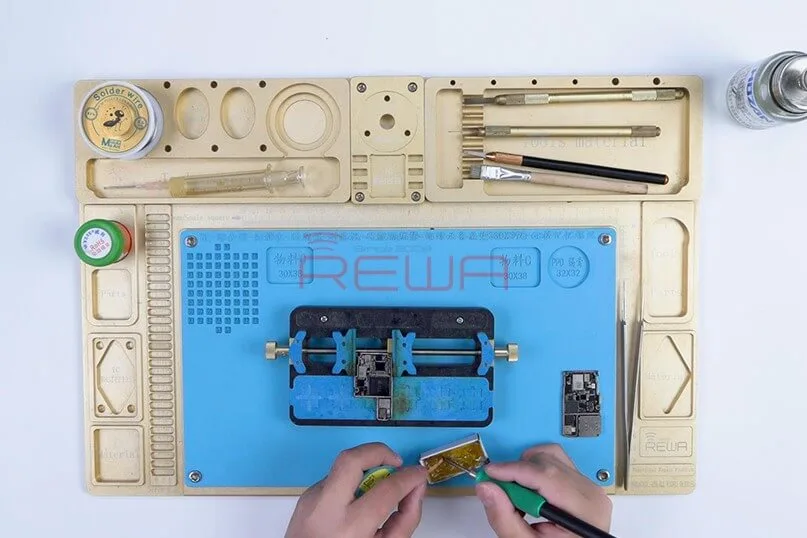
    Then we separate the motherboard to locate the faulty component. Put the motherboard on the Piattaforma di riscaldamento and set the temperature to 185℃.

    Then we separate the motherboard to locate the faulty component. Put the motherboard on the Heating Platform and set the temperature to 185℃.

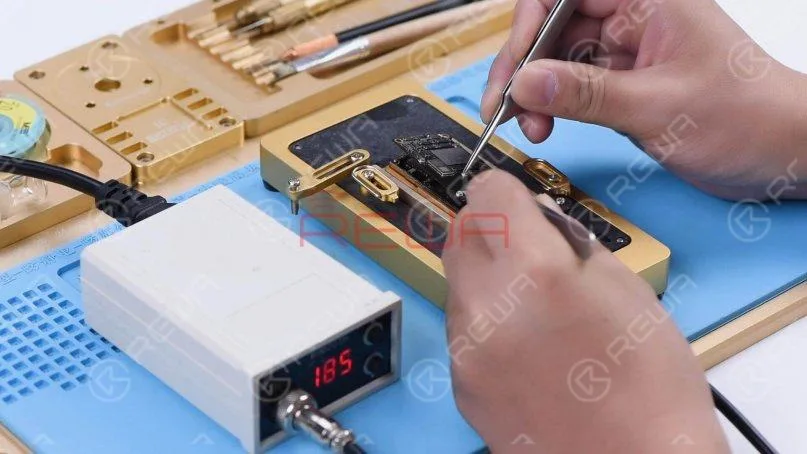
    When the temperature has risen to 185℃, remove the logic board with tweezers.
    When the temperature has risen to 185℃, remove the logic board with tweezers.

    Turn the power off and remove the signal board.

    Turn the power off and remove the signal board.

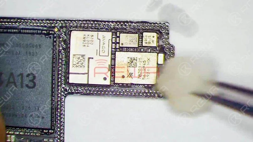
    Clean the logic board with PCB Cleaner.

    Since the signal board has been replaced, we need to check the logic board first.

    According to the test result, we can later determine whether the baseband CPU and EPROM are damaged.

    Clean the logic board with PCB Cleaner. Since the signal board has been replaced, we need to check the logic board first. According to the test result, we can later determine whether the baseband CPU and EPROM are damaged.

    Run diode mode measurement of the signal pads on the middle layer of the logic board.

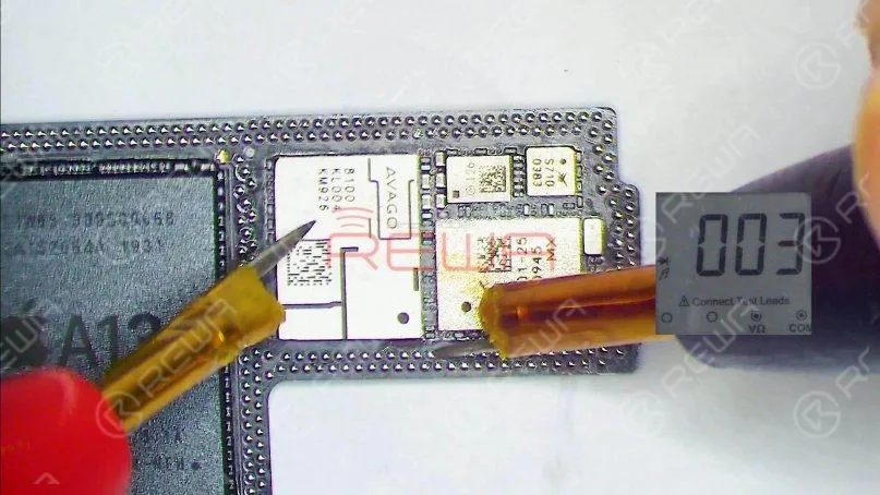
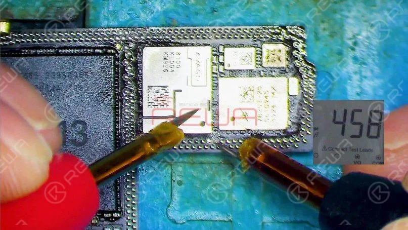
    When measuring pin 131, the diode value is 003. The normal value should be around 400.

    Run diode mode measurement of the signal pads on the middle layer of the logic board. When measuring pin 131, the diode value is 003. The normal value should be around 400.

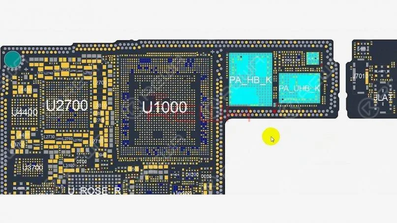
    Open the bitmap and many associated components are seen on the circuit.

    Open the bitmap and many associated components are seen on the circuit.

    Then we locate the faulty component with rosin detecting.

    Dip rosin with Soldering Iron at 365℃ and smoke some rosin on associated components.
    Then we locate the faulty component with rosin detecting. Dip rosin with Soldering Iron at 365℃ and smoke some rosin on associated components.

    Set the direct current supply to 1.8V. Connect the positive and negative anode of the direct current supply with multimeter probes.

    Set the direct current supply to 1.8V. Connect the positive and negative anode of the direct current supply with multimeter probes.

    Then connect the black probe to the ground and connect the red probe to pin 113 on the logic board. We can see rosin on a capacitor has melted.

    It indicates that the component is damaged. This circuit has multiple filter capacitors, so we can directly remove the damaged capacitor.
    Then connect the black probe to the ground and connect the red probe to pin 113 on the logic board. We can see rosin on a capacitor has melted. It indicates that the component is damaged. This circuit has multiple filter capacitors, so we can directly remove the damaged capacitor.

    Remove the capacitor with Pistola ad aria calda at 350℃ and airflow 3.

    Remove the capacitor with Hot Air Gun at 350℃ and airflow 3.

    Measure the logic board again after it has cooled. The diode value returns to a normal value of 458.
    Measure the logic board again after it has cooled. The diode value returns to a normal value of 458.

    Step 3: Motherboard restoration

    Next, we need to restore the motherboard.

    Firstly, we need to remove tin on the bonding pad of the motherboard.

    Smear rosin with Soldering Iron at 365℃ and solder-wick to remove tin on the bonding pad.

    Next, we need to restore the motherboard. Firstly, we need to remove tin on the bonding pad of the motherboard. Smear rosin with Soldering Iron at 365℃ and solder-wick to remove tin on the bonding pad.

    Remove tin on the signal board with the same method.

    After that, clean the logic board and signal board with PCB Cleaner.

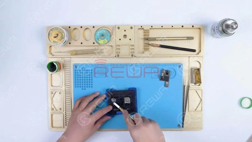
    Next, attach the signal board to the Reballing Platform and put the Reballing Stencil in position.

    Apply a layer of medium-temperature Solder Paste evenly.
    Remove tin on the signal board with the same method. After that, clean the logic board and signal board with PCB Cleaner.Next, attach the signal board to the Reballing Platform and put the Reballing Stencil in position. Apply a layer of medium-temperature Solder Paste evenly.

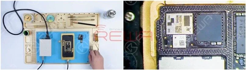
    After reballing, put the signal board on the 185℃ Heating Platform to heat.

    When the solder balls are formed, turn the power off and cool the signal board.
    After reballing, put the signal board on the 185℃ Heating Platform to heat. When the solder balls are formed, turn the power off and cool the signal board.

    Applicare alcuni Flusso di pasta to the bonding pad of the signal board and align the logic board with the signal board.
    Apply some Paste Flux to the bonding pad of the signal board and align the logic board with the signal board.

    Keep heating the motherboard on the 185℃ Heating Platform.

    Push the logic board gently with tweezers and the logic board can return to the previous position.

    It shows that the motherboard has completed soldering.

    Keep heating the motherboard on the 185℃ Heating Platform. Push the logic board gently with tweezers and the logic board can return to the previous position. It shows that the motherboard has completed soldering.

    Turn the power off and cool the motherboard for 5 minutes.

    Then remove the motherboard and install it on the phone.

    The phone turns on normally and the 4G signal can be received.

    A phone call can also be made. The fault is cleared.

    Turn the power off and cool the motherboard for 5 minutes. Then remove the motherboard and install it on the phone. The phone turns on normally and the 4G signal can be received. A phone call can also be made. The fault is cleared.

    Sintesi

    The iPhone 11 Pro Max has been repaired once and still has no service after the baseband CPU and EPROM has been welded to a good signal board.

    It can be preliminarily judged that there are two possible faults. One is the damage of baseband CPU and baseband EPROM. The other is the damage of circuits related to the signal on the logic board.

    Through measuring the signal pads on the logic board and rosin detecting, a capacitor was found damaged.

    After removing the capacitor, the no service fault was cleared.

    We can rule out the possibility of baseband CPU and EPROM fault since the no service fault was eliminated after repairing the logic board.

    Se desideri approfondire i tuoi studi, non esitare a visitare il nostro accademia per corsi di riparazione.

  • iPhone 11 Pro Max Screen Refurbishing – Detailed Operation

    Ricondizionamento dello schermo di iPhone 11 Pro Max – Operazione dettagliata

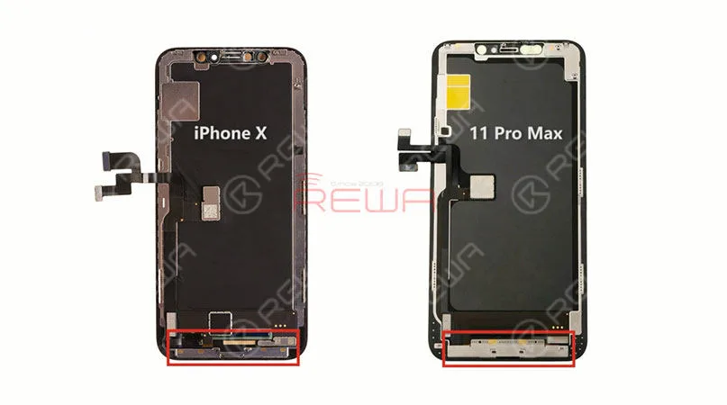
    Per iPhone X e modelli successivi, la staffa che copre l'area di collegamento del cavo flessibile inferiore è fissata con adesivo a freddo. Il metodo tradizionale con l'ausilio del calore durante la rimozione della cornice potrebbe danneggiare lo schermo. Dopo diversi tentativi, REWA LAB ha scoperto che il nuovo metodo con l'ausilio del freddo può migliorare la percentuale di successo e l'efficienza della rigenerazione dello schermo. Visita il nostro blog oggi stesso per conoscere il procedimento dettagliato della rigenerazione dello schermo di iPhone 11 Pro Max.
    Per iPhone X e modelli successivi, la staffa che copre l'area di collegamento del cavo flessibile inferiore è fissata con adesivo a freddo. Il metodo tradizionale con l'ausilio del calore durante la rimozione della cornice potrebbe danneggiare lo schermo. Dopo diversi tentativi, REWA LAB ha scoperto che il nuovo metodo con l'ausilio del freddo può migliorare la percentuale di successo e l'efficienza della rigenerazione dello schermo. Visita il nostro blog oggi stesso per conoscere il procedimento dettagliato della rigenerazione dello schermo di iPhone 11 Pro Max.

    La struttura dello schermo di iPhone 11 Pro Max è la stessa di quella della serie iPhone X. Pertanto, anche il processo di ricondizionamento dello schermo è simile. A differenza della serie iPhone X, la staffa che copre l'area di incollaggio del cavo flessibile inferiore di iPhone 11 Pro Max è relativamente larga, il che aumenta la difficoltà del ricondizionamento dello schermo. Pertanto, dobbiamo fare molta attenzione quando rimuoviamo la cornice.

    Rigenerazione schermo iPhone 11 Pro Max

    Test dello schermo della Fase 1

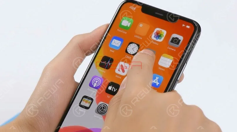
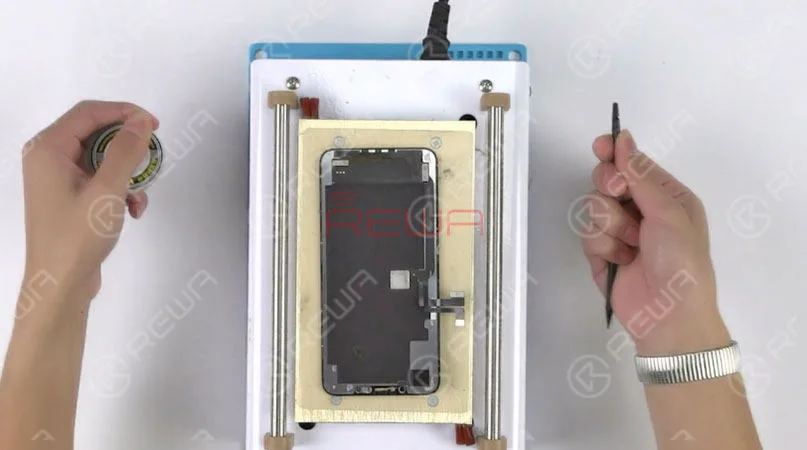
    La prima cosa che facciamo è testare lo schermo. Testare il display, la funzionalità touch e l'Haptic Touch dello schermo. Tutto procede bene.
    La prima cosa che facciamo è testare lo schermo. Testare il display, la funzionalità touch e l'Haptic Touch dello schermo. Tutto procede bene.

    Si prega di notare che, durante il test dello schermo di iPhone 11 Pro Max, la luminosità predefinita dello schermo è impostata al livello più basso. Per regolare la luminosità dello schermo durante il test, dobbiamo collegare il cavo flessibile dell'assemblaggio del sensore del pannello anteriore. Scollegare il cavo flessibile dell'assemblaggio del sensore del pannello anteriore e rimuovere l'assemblaggio dello schermo OLED. Quindi rimuovere il cavo flessibile dell'assemblaggio del sensore del pannello anteriore.
    Si prega di notare che, durante il test dello schermo di iPhone 11 Pro Max, la luminosità predefinita dello schermo è impostata al livello più basso. Per regolare la luminosità dello schermo durante il test, dobbiamo collegare il cavo flessibile dell'assemblaggio del sensore del pannello anteriore. Scollegare il cavo flessibile dell'assemblaggio del sensore del pannello anteriore e rimuovere l'assemblaggio dello schermo OLED. Quindi rimuovere il cavo flessibile dell'assemblaggio del sensore del pannello anteriore.

    Consigli: non è facile rimuovere il cavo flessibile del gruppo sensore del pannello anteriore, che può essere facilmente danneggiato durante l'operazione. E il danno può anche compromettere il funzionamento del Face ID. Quindi dobbiamo fare molta attenzione durante le operazioni

    Passaggio 2: Rimozione della lunetta

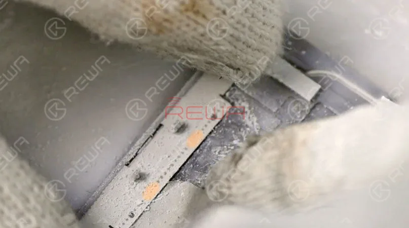
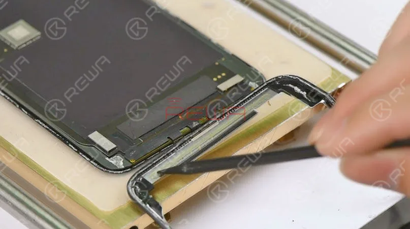
    Posiziona il gruppo dello schermo OLED capovolto nel separatore per schermi LCD congelato a -180℃. Inserisci un utensile a leva in metallo da 0,06 mm sotto la staffa che copre l'area di incollaggio del cavo flessibile inferiore. Fai scorrere avanti e indietro per tagliare l'adesivo freddo in questo punto. Una volta fatto, collega lo schermo e fai un test. Tutto procede bene.
    Posizionare il gruppo dello schermo OLED capovolto nel separatore di schermi LCD congelato a -180℃. Inserire un utensile a leva in metallo da 0,06 mm sotto la staffa che copre l'area di incollaggio del cavo flessibile inferiore. Far scorrere avanti e indietro per tagliare l'adesivo freddo in questo punto. Una volta fatto, collegare lo schermo e testarlo. Tutto procede bene.

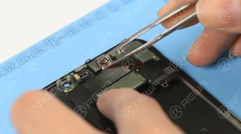
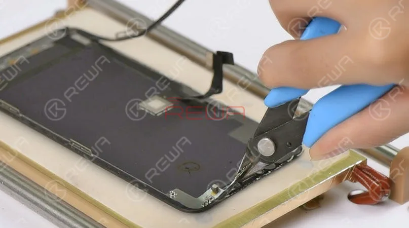
    Suggerimento: poiché il cavo flessibile del gruppo sensore del pannello anteriore non è collegato, la luminosità predefinita dello schermo è impostata al livello minimo. Impostare la temperatura della piastra termica a 100℃. Quindi posizionare il gruppo dello schermo OLED sulla piastra preriscaldata. Premere il pulsante ‘Start’ per aspirare lo schermo. 1 minuto dopo, rimuovere la fotocamera anteriore e il supporto del sensore. Tagliare la staffa superiore con le tronchesi. Quindi separare la cornice dall'OLED con le tronchesi.
    Consigli: poiché il cavo flessibile del gruppo sensore del pannello frontale non è collegato, la luminosità predefinita dello schermo è impostata al livello minimo. Impostare la temperatura della piastra riscaldante a 100℃. Quindi posizionare il gruppo dello schermo OLED sulla piastra preriscaldata. Premere il pulsante ‘Start’ per aspirare lo schermo. 1 minuto dopo, rimuovere la fotocamera frontale e il supporto del sensore. Tagliare la staffa superiore con la pinza tagliente. Quindi separare la cornice dall'OLED con la pinza tagliente.

    Consigli: quando si stacca la cornice nella parte inferiore del telefono, dobbiamo inserire il pezzo di leva in metallo sotto la staffa che copre l'area di incollaggio del cavo flessibile inferiore e farlo scorrere avanti e indietro. Questo serve a confermare che l'adesivo a freddo qui presente sia stato tagliato. La cornice è stata rimossa completamente. Come potete vedere, l'area qui è incollata da una grande quantità di adesivo a freddo. Per proteggere l'OLED da eventuali danni, è meglio congelare lo schermo durante l'operazione.
    Consigli: quando si stacca la cornice nella parte inferiore del telefono, dobbiamo inserire il pezzo di leva in metallo sotto la staffa che copre l'area di incollaggio del cavo flessibile inferiore e farlo scorrere avanti e indietro. Questo serve a confermare che l'adesivo a freddo qui presente sia stato tagliato. La cornice è stata rimossa completamente. Come potete vedere, l'area qui è incollata con adesivo a freddo in grandi quantità. Per proteggere l'OLED da danni, è meglio congelare lo schermo durante l'operazione.

    Di nuovo, testiamo l'assemblaggio dello schermo OLED. Sta andando tutto bene.

    Passaggio 3 Separazione della lente in vetro

    Ora passiamo al processo di separazione delle lenti in vetro.

    Passaggio 3 Separazione della lente in vetro Ora, passiamo al processo di separazione della lente in vetro.

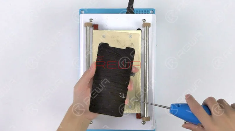
    Posiziona il gruppo dello schermo OLED capovolto sulla piastra riscaldante. Rimuovi la colla residua sull'area dell'altoparlante della capsula auricolare con una lama. In modo che il pannello touch non venga danneggiato durante l'utilizzo del filo da taglio. Successivamente, separa il vetro dal display OLED con il filo da taglio. Esegui nuovamente il test dopo la separazione. Tutto procede bene.

    Passaggio 4 Rimozione della colla OCA

    Continuiamo con la rimozione della colla OCA.

    Metti lo schermo OLED capovolto sulla piastra riscaldante per 3 minuti. Fai un'inccisione con il dispositivo elettrico per la rimozione della colla. Quindi continua a strappare la colla OCA con una mano. Inoltre, fai attenzione alla forza applicata. Questo per evitare di danneggiare lo schermo OLED. Una volta fatto, testa lo schermo OLED. Tutto va bene.

    Metti lo schermo OLED capovolto sulla piastra riscaldante per 3 minuti. Fai un'inccisione con il dispositivo elettrico per la rimozione della colla. Quindi continua a strappare la colla OCA con una mano. Inoltre, fai attenzione alla forza applicata. Questo per evitare di danneggiare lo schermo OLED. Una volta fatto, testa lo schermo OLED. Tutto va bene.

    Fase 5 Plastificazione

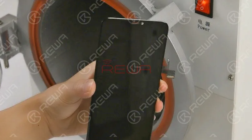
    Staccare la pellicola protettiva sul retro della lente in vetro e applicare l'OCA nella posizione corretta della lente in vetro. Quindi inserire la lente in vetro con l'OCA applicato nella macchina defelicitatrice (rimozione bolle) per 5 minuti. Una volta terminato, estrarre la lente in vetro con l'OCA applicato.
    Staccare la pellicola protettiva sul retro della lente in vetro e applicare l'OCA nella posizione corretta della lente in vetro. Quindi inserire la lente in vetro con l'OCA applicato nella macchina defelicitatrice (rimozione bolle) per 5 minuti. Una volta terminato, estrarre la lente in vetro con l'OCA applicato.

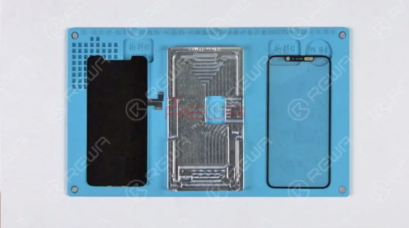
    Ora dobbiamo laminare la lente in vetro con OCA applicato sullo schermo OLED. Posiziona lo schermo OLED nello stampo di allineamento OLED. Pulisci lo schermo con il panno privo di pelucchi. Rimuovi un altro strato della pellicola protettiva OCA e applica la lente in vetro con OCA nella posizione corretta dello schermo. Premi delicatamente per far aderire la lente in vetro allo schermo. Posiziona lo stampo capovolto ed estrai il gruppo dello schermo OLED. Rimuovi la pellicola protettiva sulla lente in vetro. Copri il retro del gruppo dello schermo OLED con una spugna per laminazione e quindi posiziona il gruppo dello schermo OLED nella macchina laminatrice. Scegli ‘avvia’ sul pannello LED. La macchina inizia a lavorare. La laminazione è terminata dopo diversi minuti. Di nuovo, testiamo il gruppo dello schermo OLED. Tutto procede bene.

    Fase 6: Rimozione delle bolle

    Inserire il gruppo schermo OLED nella macchina rimuovi bolle per 10 minuti. Una volta terminato, estrarre il gruppo schermo OLED.

    Inserire il gruppo schermo OLED nella macchina rimuovi bolle per 10 minuti. Una volta terminato, estrarre il gruppo schermo OLED.

    Passaggio 7 Fissaggio della ghiera

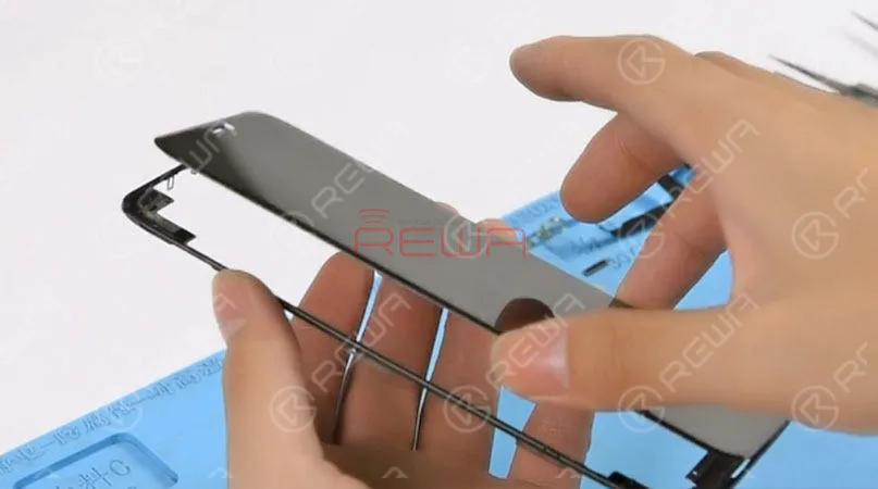
    Prepara un nuovo pezzo di cornice per iPhone 11 Pro Max. Stacca la pellicola protettiva dalla cornice. Applica la colla specializzata sulla cornice. Quindi applica pressione per montare l'assemblaggio dello schermo OLED con la cornice.

    Prepara un nuovo pezzo di cornice per iPhone 11 Pro Max. Stacca la pellicola protettiva dalla cornice. Applica la colla specializzata sulla cornice. Quindi applica pressione per montare l'assemblaggio dello schermo OLED con la cornice.

    Si prega di notare che l'area FPC sul fondo è molto fragile. Fare attenzione durante l'utilizzo. In caso contrario, si potrebbe danneggiare lo schermo OLED.
    Si prega di notare che l'area FPC sul fondo è molto fragile. Fare attenzione durante l'utilizzo. In caso contrario, si potrebbe danneggiare lo schermo OLED.

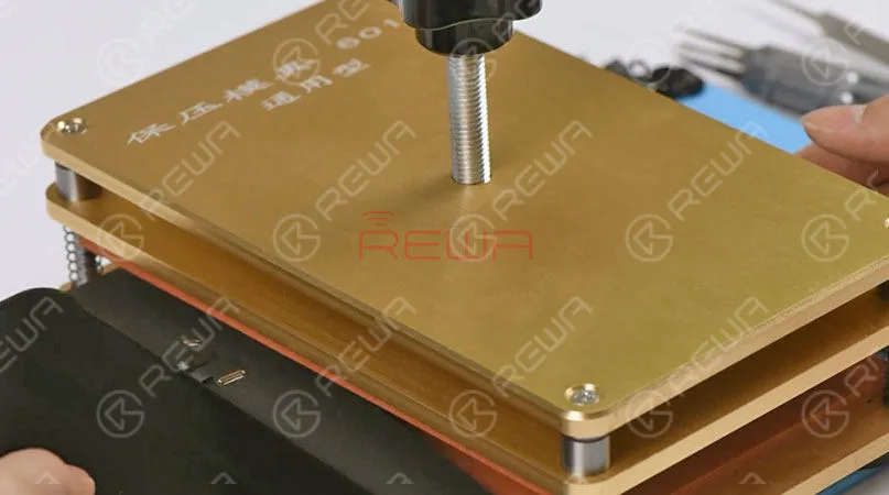
    Rivestire il retro dell'unità dello schermo OLED con una spugna per laminazione. Quindi posizionare l'unità dello schermo OLED nello stampo di laminazione della cornice e fissarla. Stringere la vite e attendere 10 minuti. Estrarre successivamente l'unità dello schermo OLED.

    Test dello schermo del passaggio 8

    Installare il supporto per la fotocamera anteriore e i sensori, e successivamente la retina dell'altoparlante auricolare. Installare il cavo flessibile dell'assemblaggio dei sensori del pannello anteriore e l'assemblaggio dello schermo OLED. Eseguire il test di funzionamento – Display; Touch; Haptic Touch. Display, Touch e Haptic Touch funzionano normalmente.
    Installa il supporto per la fotocamera anteriore e i sensori, e successivamente la retina dell'altoparlante auricolare. Installa il cavo flex dell'assemblaggio dei sensori del pannello anteriore e l'assemblaggio dello schermo OLED. Esegui il test delle funzioni: Display; Touch; Haptic Touch. Display, Touch e Haptic Touch funzionano normalmente.

    La rigenerazione dello schermo dell'iPhone 11 Pro Max è stata completata perfettamente.

    Strumenti e parti usate

    Potete anche visitare Canale Youtube REWA  per guardare il nostro video sulla rigenerazione dell'iPhone 11 Pro Max.

  • Turn iPhone 11 Pro Into iPhone 11 Pro Max

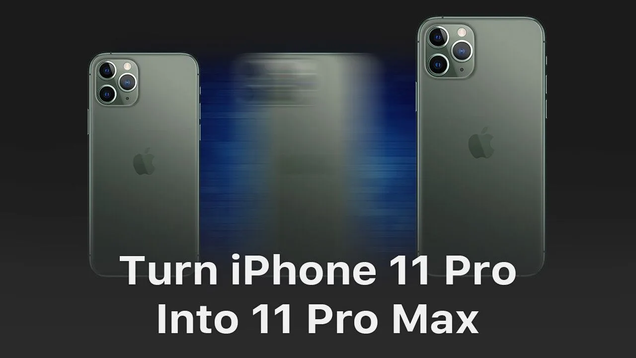
    Turn iPhone 11 Pro Into iPhone 11 Pro Max

    Can iPhone 11 Pro possibly be turned into iPhone 11 Pro Max? It is actually theoretically possible. With pins of the two phones’ display connector and touch connector functioning almost the same, we can turn an iPhone 11 Pro into an iPhone 11 Pro Max by changing board ID resistors. Check our video now and find out how we finally made it.

    Warm Tips: This video is made for technique sharing only. For those who have no professional skills, please look before you leap.

    Tools & Parts used to separate iPhone 11 Pro: