Étiquette : iphone won’t turn on

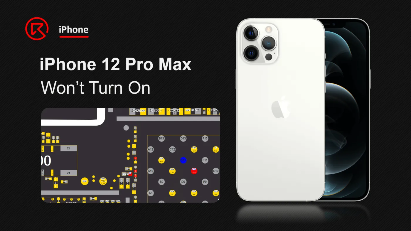
  • iPhone 12 Pro Max Won’t Turn On Issue Repair Guide

    Guide de réparation du problème de l'iPhone 12 Pro Max qui ne s'allume pas

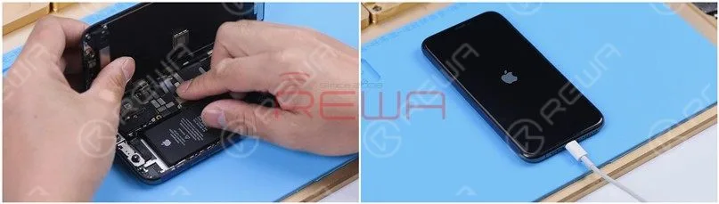
    The iPhone 12 Pro Max, announced on October 13, 2020, is a high-end smartphone known for its advanced features. However, a serious drop can cause it to fail to turn on. This guide details the steps to troubleshoot and repair this issue.

    iphone 12 pro max cannot charge stuck apple logo

    Détails du téléphone

    Modèle : iPhone 12 Pro Max

    Annoncé : 2020, 13 octobre

    Phénomène de défaut

    An iPhone 12 Pro Max that has been seriously damaged by a drop may not turn on. In such cases, the following troubleshooting and repair process can be helpful.

    Processus de dépannage

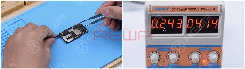
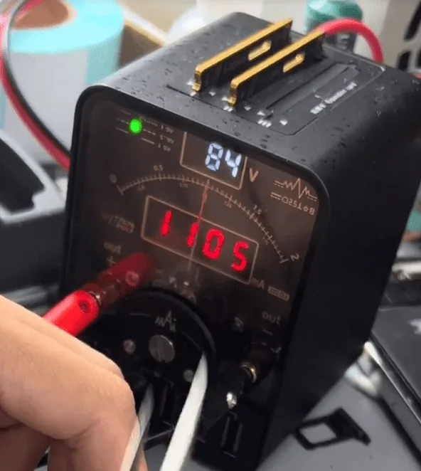
    First, let’s connect the motherboard with the DC power supply machine, there’s no current leakage. But when triggering the boot process by tweezer, the current jump to 1100mA directly.
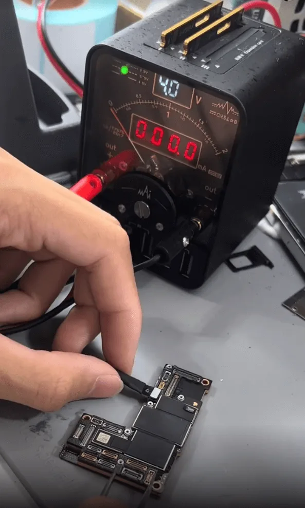
    iphone 12 pro max won turn issue repair guide trigger to boot
    iphone 12 pro max won turn issue repair guide 1100ma directly

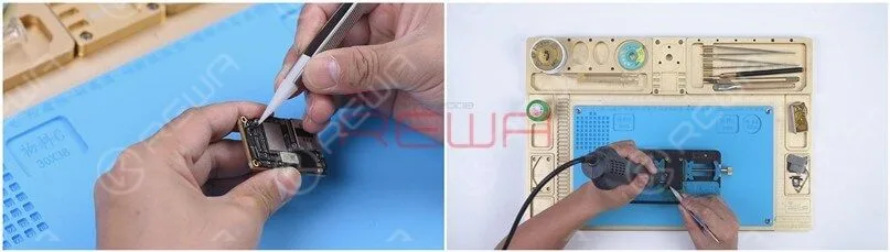
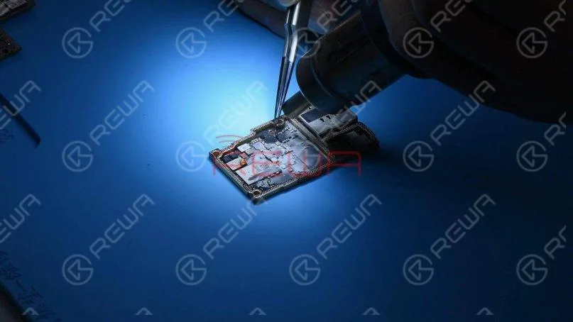
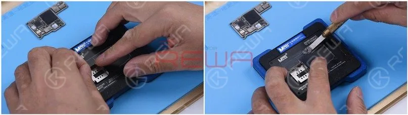
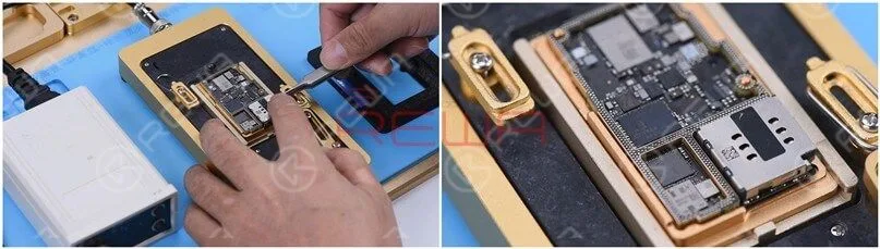
    Next, let’s remove the foams around the connectors, and then hold the motherboard on the heating platform to separate the two layers of the motherboard.
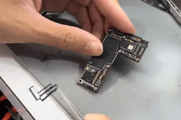
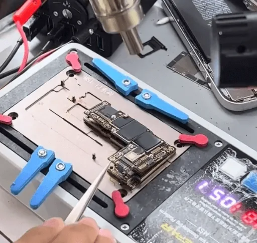
    iphone 12 pro max won turn issue repair guide remove the foams around
    iphone 12 pro max won turn issue repair guide separate with the heating

    After separation, not surprisingly, a lot of pads have fallen off, later we need to take a lot of time to fix the missing pads. But anyway, let’s fix the boot issue first.

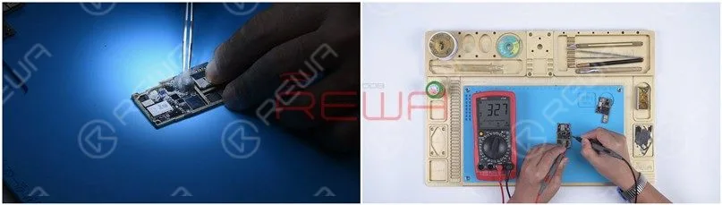
    When measuring the diode values on the power rails which are outputted from PMU to CPU, find one capacitor around the CPU is shorted to the ground.
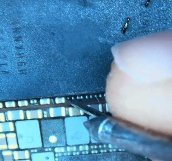
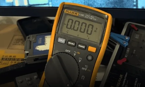
    iphone 12 pro max won turn issue repair guide when measuring with
    iphone 12 pro max won turn issue repair guide find one rail is shorted

    Refer to the Refox bitmap, it’s PP1V2_IO.

    As we can see, there are many components related to the PP1V2_IO.
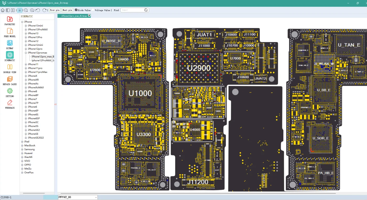
    iphone 12 pro max won turn issue repair guide refox bitmap

    To find out the exact shorted component, we need to use the rosin inspection method.

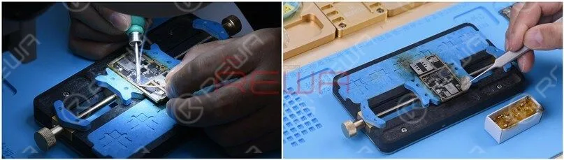
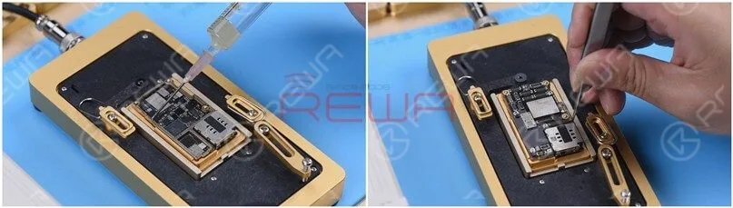
    Apply rosin smoke on the surface of the relative areas on the motherboard
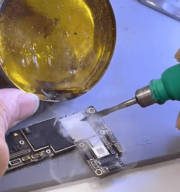
    iphone 12 pro max won turn issue repair guide apply rosin smoke on the

    Then connect the motherboard with the DC power supply machine and check under the microscope, we can find the shorted component easily.
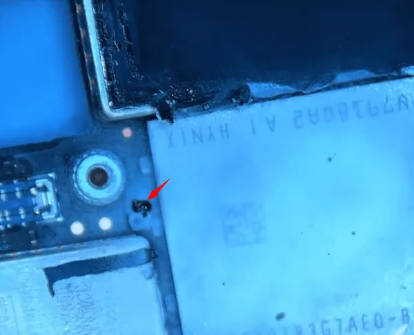
    iphone 12 pro max won turn issue repair guide the shorted capacitor

    Refer to the bitmap, it’s the capacitor C2941
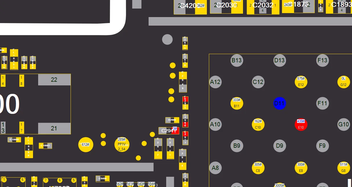
    iphone 12 pro max won turn issue repair guide c2941

    Since it’s a filter-type capacitor, to avoid the potential heat damage to the NAND and connectors around it. We can just pick it off with tweezers directly.

    After that, connect the logic board with the screen and boot with the DC power supply machine again, the phone can be booted.
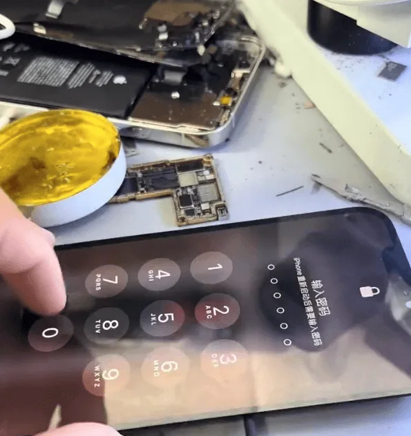
    iphone 12 pro max won turn issue repair guide phone can be booted

    Then, let’s fix the missing pads on the middle layer.
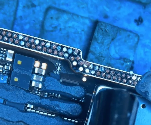
    iphone 12 pro max won turn issue repair guide the missing pads on middle

    Fixing the missing pads is not very difficult but requires a lot of patience.

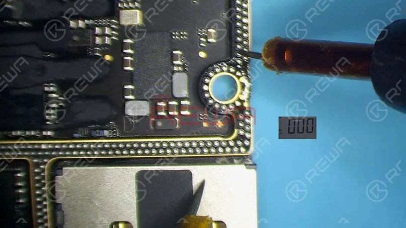
    For the pad that has no connection point
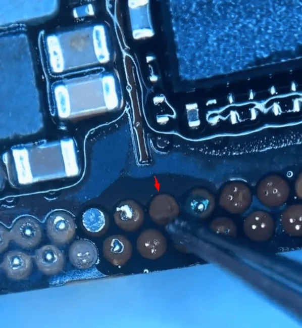
    iphone 12 pro max won turn issue repair guide for the pad that has no

    We need to scratch out the root of the pad with a sculpture knife slightly first
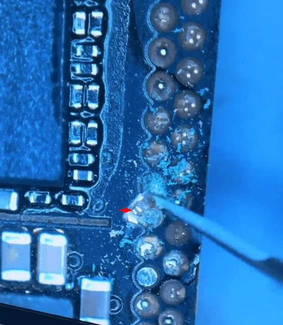
    iphone 12 pro max won turn issue repair guide scratch out the pads

    After that, based on the “root” to jump wire and make a circle
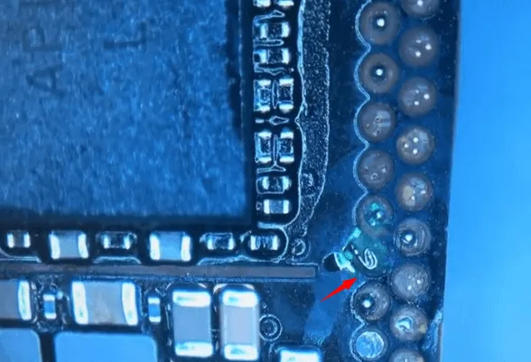
    iphone 12 pro max won turn issue repair guide make circle

    Then solder a copper lug on the surface
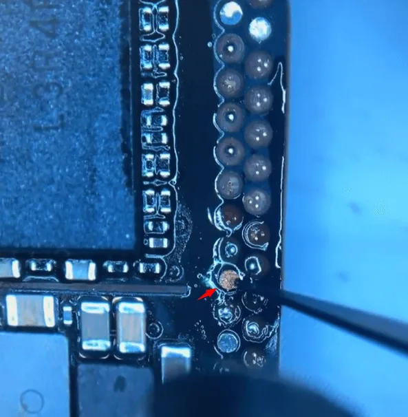
    iphone 12 pro max won turn issue repair guide solder copper lug on the

    Then cure and reinforce it with the UV mask and UV lamp.
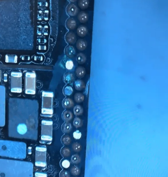
    iphone 12 pro max won turn issue repair guide cure with the uv lamp

    Assembler et tester

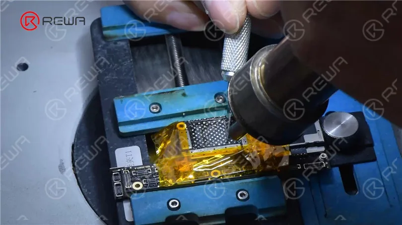
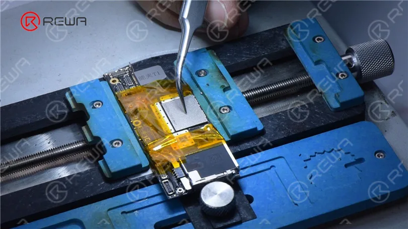
    Then assemble the two layers of the motherboard first with the heating platform
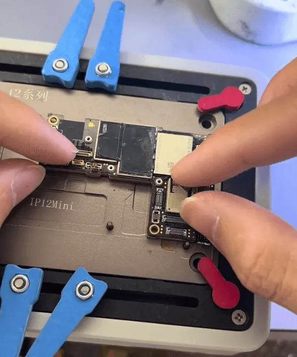
    iphone 12 pro max won turn issue repair guide heating platform

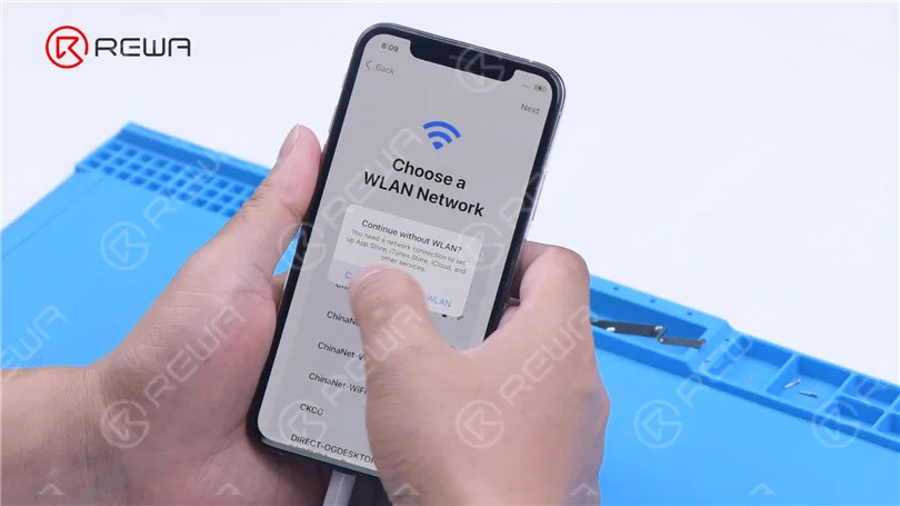
    When the motherboard cooling down, assemble the phone to test and all the functions are OK.

    The issue gets resolved by removing the damaged capacitor and recombining the two layers of the motherboard.
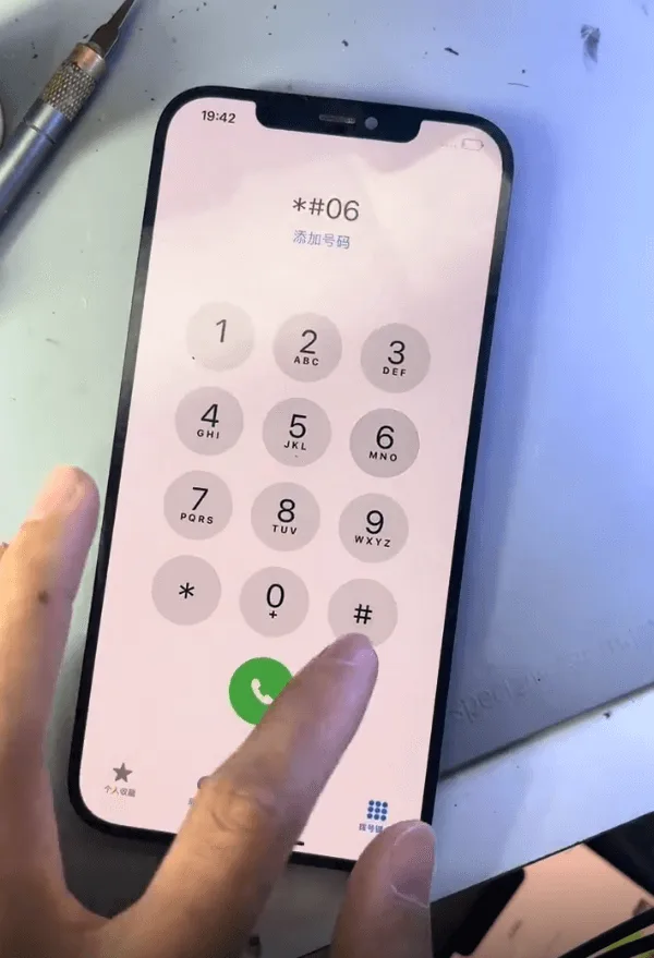
    iPhone 12 Pro Max Won't Turn On

    Résumé

    The iPhone 12 Pro Max issue of not turning on due to serious drop damage was resolved by:

    • Removing the damaged capacitor (C2941).
    • Recombining the two layers of the motherboard.
    • Fixing the missing pads.

    This repair requires careful inspection and precise work to ensure the phone is restored to full functionality without causing additional damage.
  • Fix iPhone XS Won’t Turn On with P12 (NAND Programmer for iPhone 6 – iPhone 11 Pro Max)

    Fixer iPhone XS ne s'allume pas avec P12 (Programmeur NAND pour iPhone 6 - iPhone 11 Pro Max)

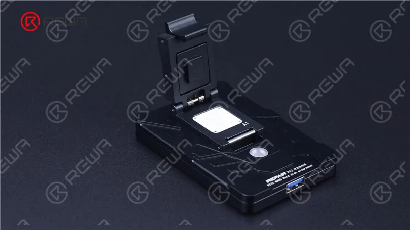
    Le remplacement de la NAND est une procédure courante dans la réparation d'un iPhone, que ce soit pour mettre à niveau le stockage ou pour résoudre des problèmes tels que l'impossibilité d'allumer l'appareil en raison d'une NAND endommagée. Pour le remplacement de la carte NAND, un programmateur NAND est nécessaire pour lire et écrire les données de la carte NAND.

    Fixer iPhone XS ne s'allume pas avec P12 (Programmeur NAND pour iPhone 6 - iPhone 11 Pro Max)

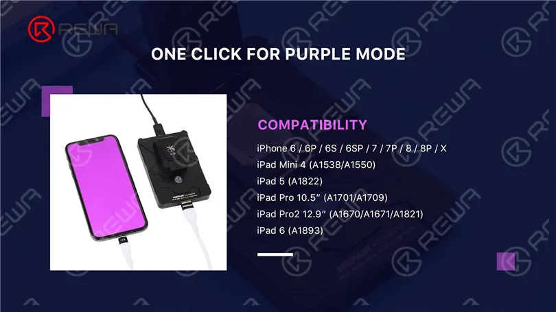
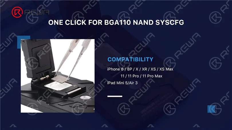
    Aujourd'hui, nous allons réparer un iPhone avec le dernier programmateur NAND. P12Comparé à d'autres programmateurs NAND sur le marché, P12 prend en charge un large éventail de modèles, y compris la lecture et l'écriture NAND et le débridage WiFi pour l'iPhone 6-iPhone 11 Pro Max et certains modèles d'iPad. De plus, P12 peut fonctionner sans connexion Internet et son utilisation est gratuite et permanente.

    Fixer iPhone XS ne s'allume pas avec P12 (Programmeur NAND pour iPhone 6 - iPhone 11 Pro Max)
    Fixer iPhone XS ne s'allume pas avec P12 (Programmeur NAND pour iPhone 6 - iPhone 11 Pro Max)
    Fixer iPhone XS ne s'allume pas avec P12 (Programmeur NAND pour iPhone 6 - iPhone 11 Pro Max)

    Ensuite, nous utilisons P12 pour réparer un iPhone XS qui ne s'allume pas. L'iPhone XS ne parvient pas à démarrer.

    Fixer iPhone XS ne s'allume pas avec P12 (Programmeur NAND pour iPhone 6 - iPhone 11 Pro Max)

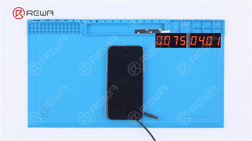
    Ensuite, nous démontons le téléphone pour la suite des tests. Connecter la carte mère avec Câble d'alimentation. Le courant de démarrage n'est que de 75 mA. On peut estimer à priori que le système est défectueux.

    Fixer iPhone XS ne s'allume pas avec P12 (Programmeur NAND pour iPhone 6 - iPhone 11 Pro Max)

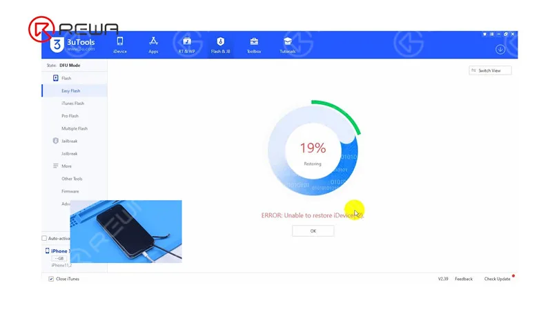
    Ensuite, connectez le téléphone à l'ordinateur. Le téléphone passe automatiquement en mode DFU. Le clignotement reste bloqué à 19%. Nous pouvons maintenant confirmer que le problème de blocage est dû à des circuits défectueux liés à la NAND.

    Fixer iPhone XS ne s'allume pas avec P12 (Programmeur NAND pour iPhone 6 - iPhone 11 Pro Max)

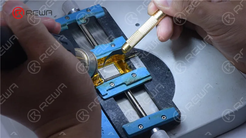
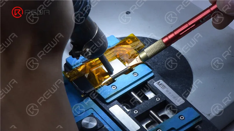
    L'étape suivante consiste à remplacer la carte NAND par une nouvelle. Retirez l'écran et détachez la carte mère. Appliquez du ruban adhésif haute température autour de la carte mère. Tout d'abord, enlevez l'adhésif noir autour de la NAND à l'aide d'un pistolet à air chaud à 280 °C.

    Fixer iPhone XS ne s'allume pas avec P12 (Programmeur NAND pour iPhone 6 - iPhone 11 Pro Max)

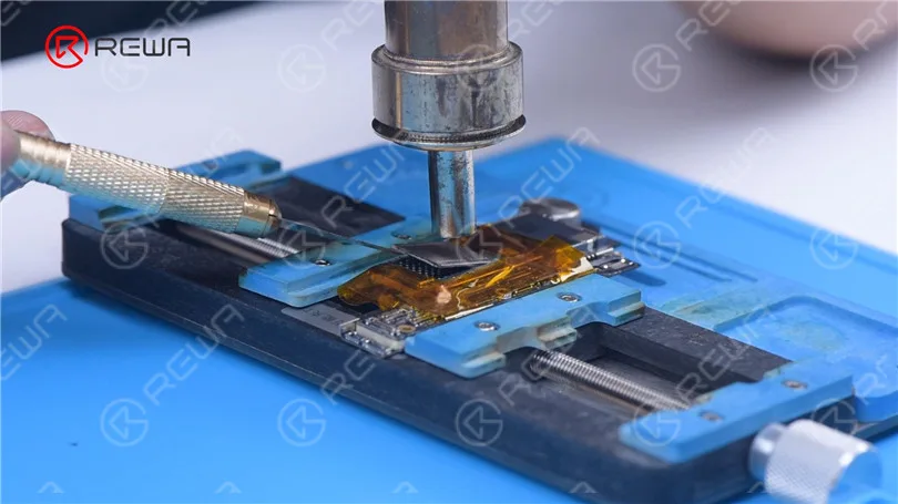
    Décoller le NAND avec un pistolet à air chaud à 400 °C.

    Fixer iPhone XS ne s'allume pas avec P12 (Programmeur NAND pour iPhone 6 - iPhone 11 Pro Max)

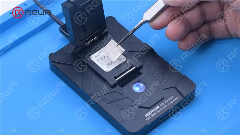
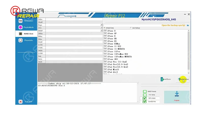
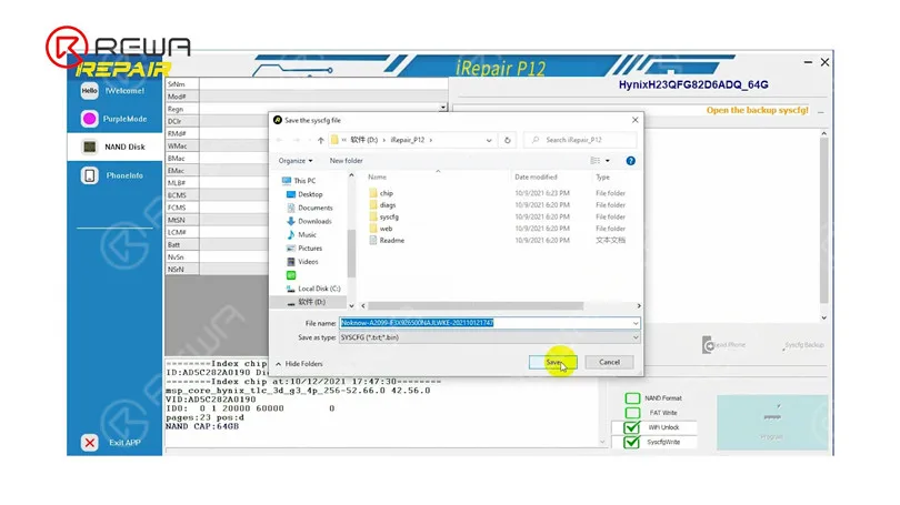
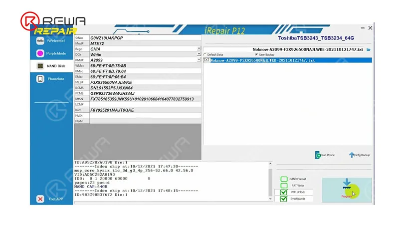
    Fixez la carte NAND à P12. Veillez à aligner la carte NAND avec la broche A1. Cliquez sur "Syscfg Backup". Sauvegardez ensuite les données.

    Fixer iPhone XS ne s'allume pas avec P12 (Programmeur NAND pour iPhone 6 - iPhone 11 Pro Max)
    Fixer iPhone XS ne s'allume pas avec P12 (Programmeur NAND pour iPhone 6 - iPhone 11 Pro Max)
    Fixer iPhone XS ne s'allume pas avec P12 (Programmeur NAND pour iPhone 6 - iPhone 11 Pro Max)

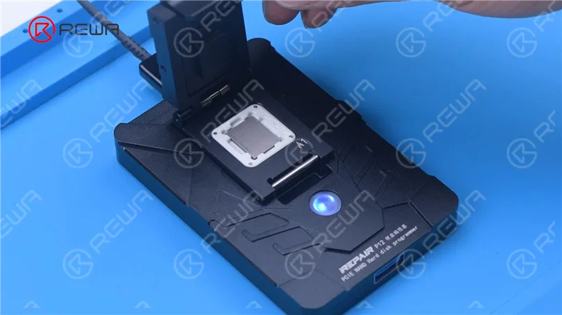
    Retirer la carte NAND. Attachez la nouvelle carte NAND à P12. Sélectionnez "User Backup". Appuyez sur "Program".

    Fixer iPhone XS ne s'allume pas avec P12 (Programmeur NAND pour iPhone 6 - iPhone 11 Pro Max)
    Fixer iPhone XS ne s'allume pas avec P12 (Programmeur NAND pour iPhone 6 - iPhone 11 Pro Max)

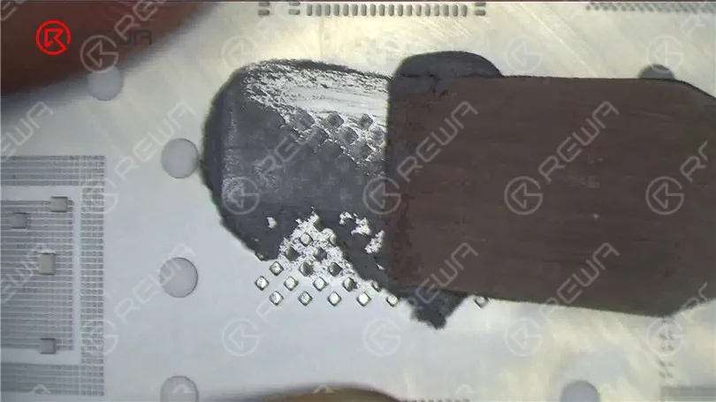
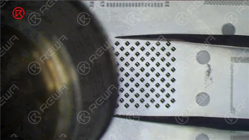
    Ensuite, nous reballons la NAND avec les données écrites. Placez le pochoir de reballage en position. Appliquez uniformément une couche de pâte à braser à température moyenne. Chauffer avec un pistolet à air chaud à 340 °C.

    Fixer iPhone XS ne s'allume pas avec P12 (Programmeur NAND pour iPhone 6 - iPhone 11 Pro Max)
    Fixer iPhone XS ne s'allume pas avec P12 (Programmeur NAND pour iPhone 6 - iPhone 11 Pro Max)

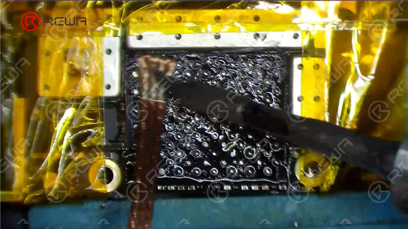
    Avant de souder les cartes NAND, il faut éliminer l'étain sur les patins de liaison. Appliquez de la pâte à souder à température moyenne à l'aide d'un fer à souder. Nettoyez les plages de connexion avec le fer à souder et la mèche à souder.

    Fixer iPhone XS ne s'allume pas avec P12 (Programmeur NAND pour iPhone 6 - iPhone 11 Pro Max)

    Enlever l'adhésif noir sur les patins de collage avec le couteau à sculpter. Nettoyer ensuite les plots de collage avec le PCB Cleaner. Après le nettoyage, appliquer un peu de Paste Flux

    Aligner la nouvelle carte NAND. Chauffer avec un pistolet à air chaud à 380 °C pour souder.

    Fixer iPhone XS ne s'allume pas avec P12 (Programmeur NAND pour iPhone 6 - iPhone 11 Pro Max)
    Fixer iPhone XS ne s'allume pas avec P12 (Programmeur NAND pour iPhone 6 - iPhone 11 Pro Max)

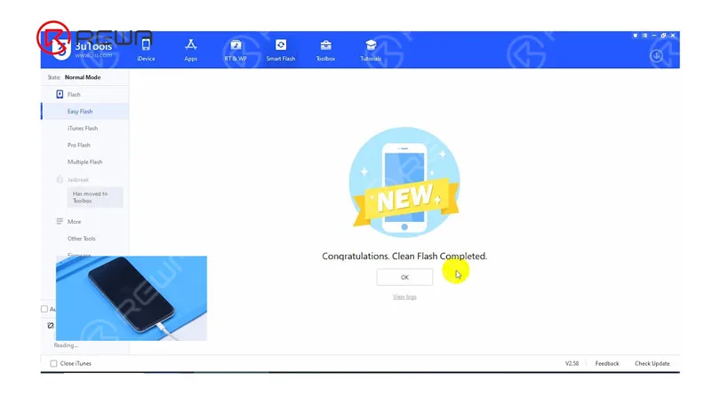
    Ensuite, nous installons la carte mère. Connectez le téléphone à l'ordinateur pour le flashage. Le flashage a réussi.
    Fixer iPhone XS ne s'allume pas avec P12 (Programmeur NAND pour iPhone 6 - iPhone 11 Pro Max)

    Le téléphone s'allume normalement. Après l'activation, le téléphone fonctionne bien.

    Fixer iPhone XS ne s'allume pas avec P12 (Programmeur NAND pour iPhone 6 - iPhone 11 Pro Max)
  • Réparer un iPhone 7/7 Plus qui ne s'allume pas – Réparation du processeur (CPU)

    Réparer un iPhone 7/7 Plus qui ne s'allume pas – Réparation du processeur (CPU)

    iPhone 7/7 Plus won’t turn on after it is dropped? Due to the imperfect technology of CPU supplier, the SDRAM of iPhone 7/7 Plus series can be easily damaged. Once dropped, the SDRAM might be short circuited and the phone won’t turn on afterwards. The traditional SDRAM replacing method is complex and easy to get it pseudo soldered. This time we introduced a new solution with CNC Chip Grinding Machine. Let’s check the video to see how we fix iPhone 7 plus won’t power on issue in a more efficient way.

  • Fix iPhone 12 Won’t Turn On By Infrared Thermal Imaging Camera

    Fix iPhone 12 Won’t Turn On By Infrared Thermal Imaging Camera

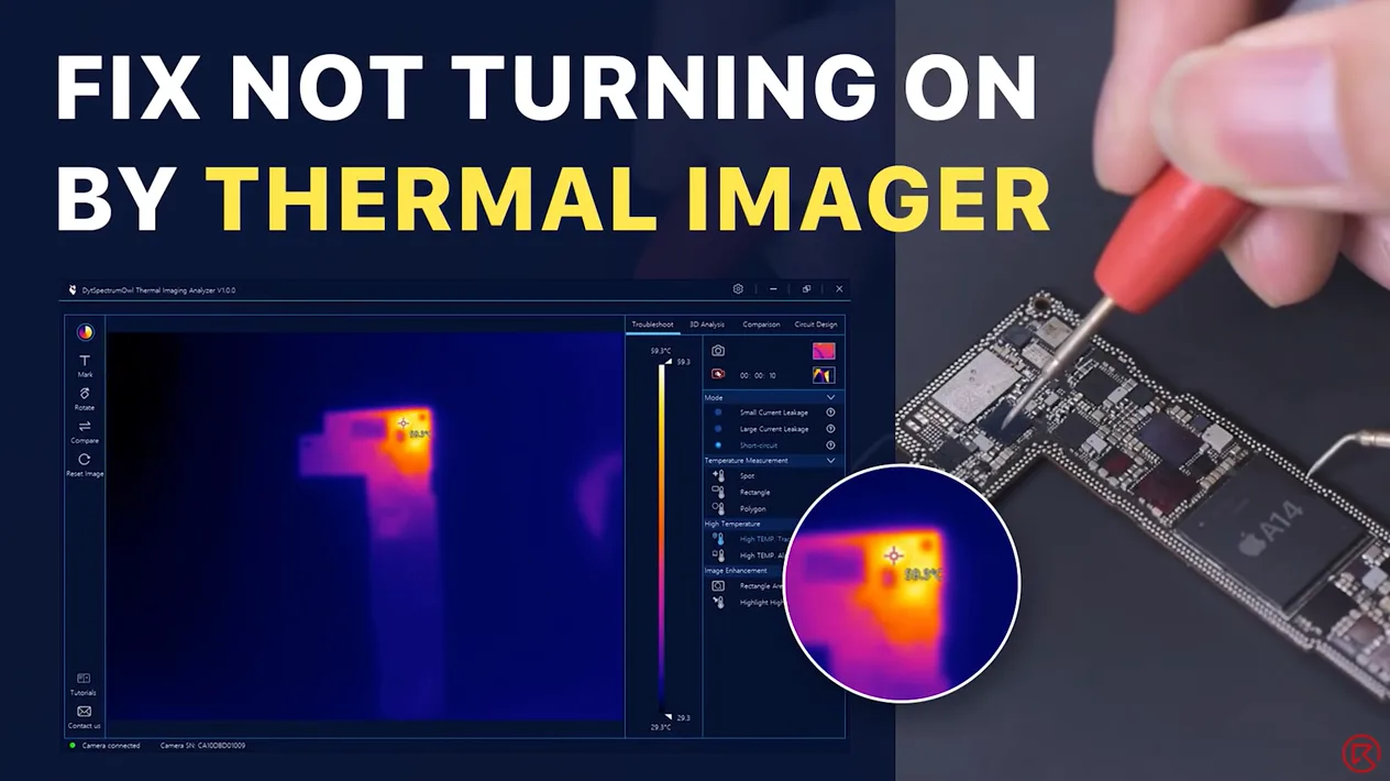
    Today we will share a repair case of an iPhone 12 that won’t turn on. After multiple attempts to turn on the iPhone 12, the iPhone 12 still won’t turn on. We have excluded the possibility of the display assembly and battery faults, so we speculate the cause is the short circuit of the motherboard. To find the faulty part, we have used the latest infrared thermal imager camera that differs from the complicated rosin detecting. Let’s check it out!

  • How to Fix an iPhone 11 Pro Won’t Turn On

    How to Fix an iPhone 11 Pro Won’t Turn On

    Having trouble with your iPhone 11 Pro refusing to turn on? Don’t worry, we’ve got your back! In this comprehensive guide, we’ll walk you through some practical and effective solutions to fix this frustrating issue.

    Step 1: Disassemble and test

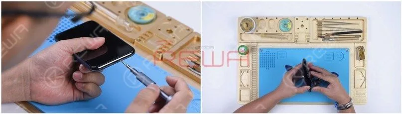
    Remove the two pentalobe screws at the bottom edge and lift the screen.
    Remove the two pentalobe screws at the bottom edge and lift the screen.

    After the screen is lifted, take the shielding covers off, disconnect the battery, and remove the screen.
    After the screen is lifted, take the shielding covers off, disconnect the battery, and remove the screen.

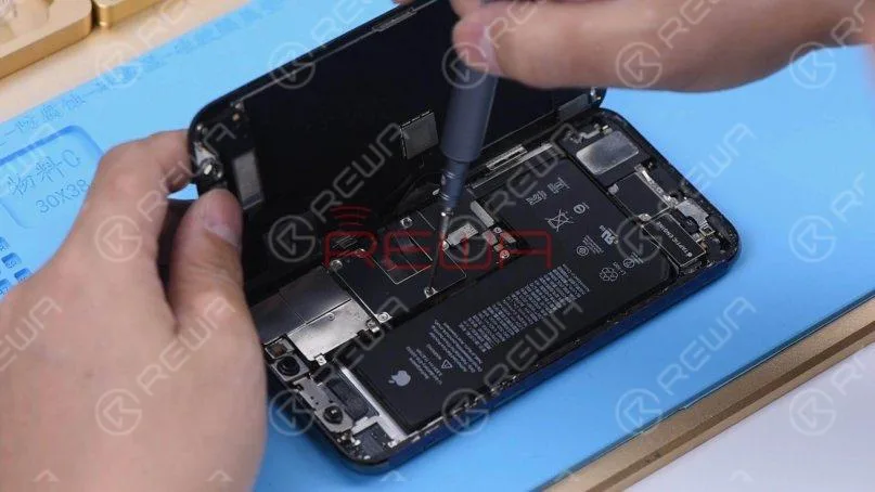
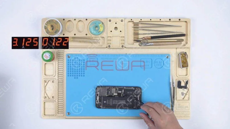
    Connect the motherboard with the Power Cable. The ammeter shows a large current of 3.1A.
    Connect the motherboard with the Power Cable. The ammeter shows a large current of 3.1A.

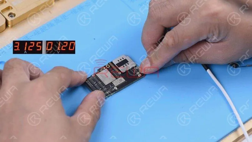
    Detach the motherboard and connect the motherboard with the Power Cable again. The ammeter still shows a large current of 3.1A.
    Detach the motherboard and connect the motherboard with the Power Cable again. The ammeter still shows a large current of 3.1A.

    It indicates that the large current has nothing to do with other flex cables. The fault is on the motherboard.

    Step 2: Run diode mode measurement

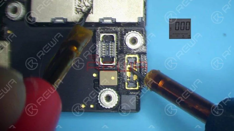
    Run diode mode measurement of pin 1 on the J7010 of the battery connector. The diode value is 0 which indicates that the main power supply circuit is shorted to the ground.

    Run diode mode measurement of pin 1 on the J7010 of the battery connector. The diode value is 0 which indicates that the main power supply circuit is shorted to the ground.

    Étant donné que le circuit alimente simultanément la carte logique et la carte signal, nous devons séparer la carte mère pour localiser la panne.

    Step 3: Motherboard separation

    Remove foam on the motherboard. Then heat the back of the motherboard with Pistolet à air chaud at 240℃ to remove the shielding paper.
    Remove foam on the motherboard. Then heat the back of the motherboard with Hot Air Gun at 240℃ to remove the shielding paper.

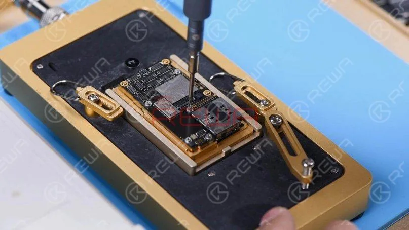
    Placez la carte mère sur le Plate-forme de chauffage. To make it easier to remove the logic board after separation, drive a screw on the logic board.
    Put the motherboard on the Heating Platform. To make it easier to remove the logic board after separation, drive a screw on the logic board.

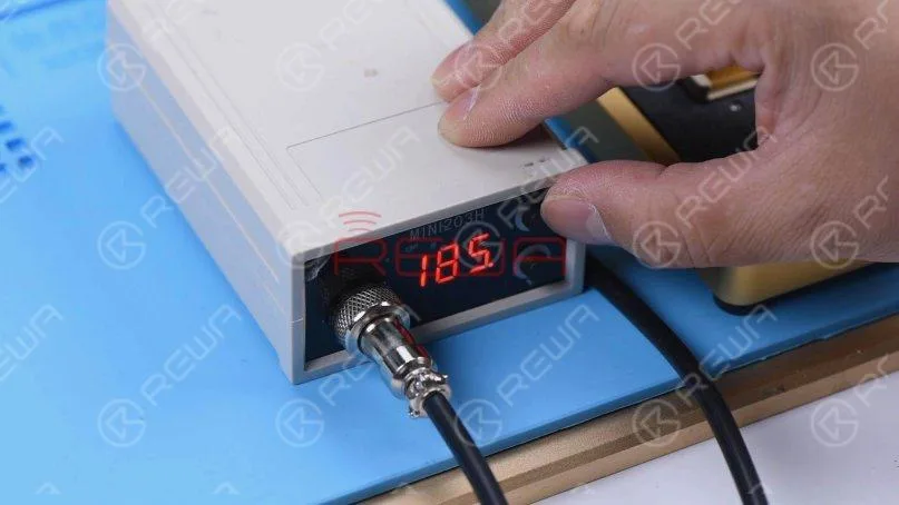
    Set the temperature of the Heating Platform to 185℃.

    Set the temperature of the Heating Platform to 185℃.

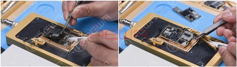
    Clamp the screw to remove the logic board when the temperature has risen to 185℃. Lastly, remove the signal board.
    Clamp the screw to remove the logic board when the temperature has risen to 185℃. Lastly, remove the signal board.

    Step 4: Run diode mode measurement again

    Run diode mode measurement of pin 286 on the signal board. The diode value is 0. It suggests that the main power supply of the signal board is shorted to the ground.

    Run diode mode measurement of pin 286 on the signal board. The diode value is 0. It suggests that the main power supply of the signal board is shorted to the ground.

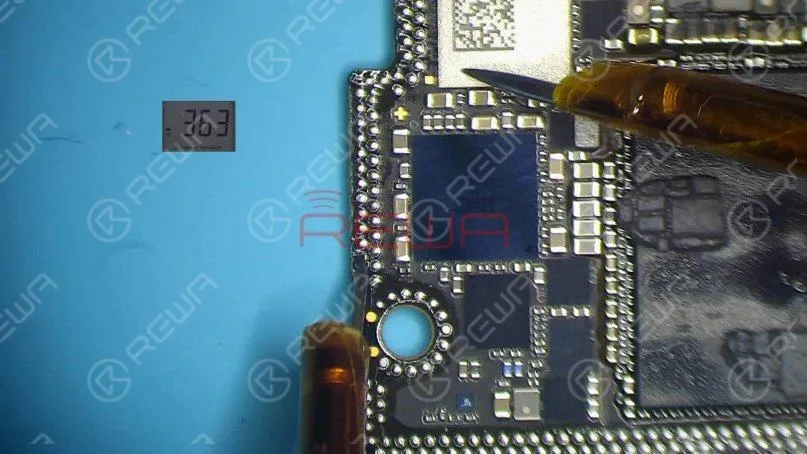
    Measure pin 286 on the logic board. The diode value is 363 which means the logic board is normal.

    Measure pin 286 on the logic board. The diode value is 363 which means the logic board is normal.

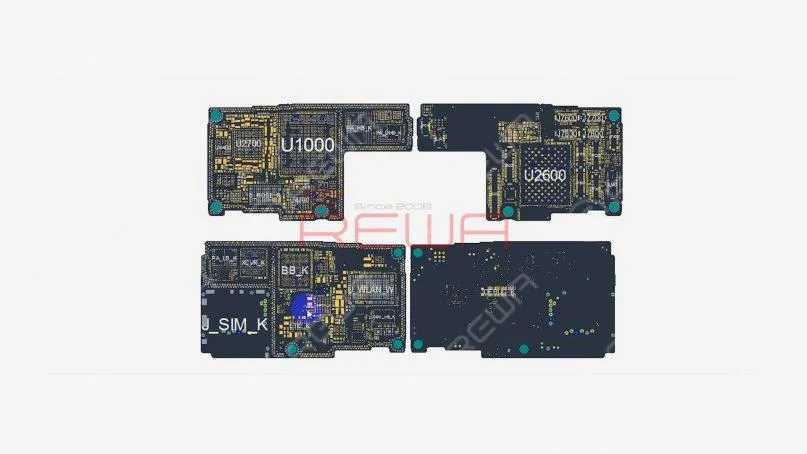
    Open the bitmap. We can see there are many associated components on the main power supply circuit.

    Ouvrez l'image bitmap. Nous pouvons voir qu'il y a de nombreux composants associés sur le circuit d'alimentation principal.

    Step 5: Rosin detecting to locate the fault

    Next, we need to locate the faulty component with rosin detecting.Remove thermal grease with a Sculpture Knife. Then dip rosin with Fer à souder at 365℃ and smoke rosin on the signal board.
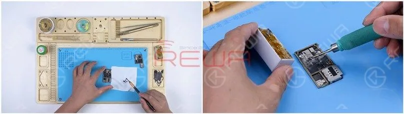
    Next, we need to locate the faulty component with rosin detecting.Remove thermal grease with a Sculpture Knife. Then dip rosin with Soldering Iron at 365℃ and smoke rosin on the signal board.

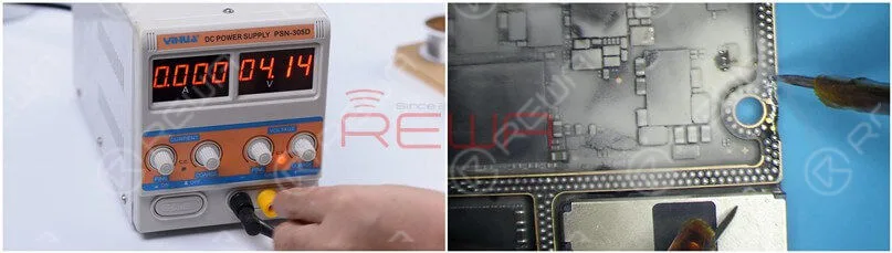
    Set the direct current supply to 4.1V. Connect the positive and negative anode of the direct current supply with multimeter probes. Connect the black probe to the ground and connect the red probe to pin 286 on the signal board. We can see rosin on C1200_K has melted. It indicates that the capacitor is damaged.

    Set the direct current supply to 4.1V. Connect the positive and negative anode of the direct current supply with multimeter probes. Connect the black probe to the ground and connect the red probe to pin 286 on the signal board. We can see rosin on C1200_K has melted. It indicates that the capacitor is damaged.

    Step 6: Eliminate the fault and restore the motherboard

    Then we heat the damaged capacitor with Hot Air Gun at 350℃ and remove it with tweezers.

    Then we heat the damaged capacitor with Hot Air Gun at 350℃ and remove it with tweezers.

    Nettoyez la colophane sur la carte de signal avec du PCB Cleaner. Effectuez une deuxième mesure en mode diode. La valeur de la diode revient à une valeur normale de 327.

    Nettoyez la colophane sur la carte de signal avec du PCB Cleaner. Effectuez une deuxième mesure en mode diode. La valeur de la diode revient à une valeur normale de 327.

    Smear rosin with Soldering Iron and solder wick at 365℃ to remove tin on the bonding pad. Clean the signal board with PCB Cleaner.

    Smear rosin with Soldering Iron and solder wick at 365℃ to remove tin on the bonding pad. Clean the signal board with PCB Cleaner.

    Remove tin and clean the logic board with the same method.Attach the signal board to the Reballing Platform and put the Reballing Stencil in position. To prevent the solder paste from flowing into the motherboard crevices, insert a metal plate. Apply a layer of low-temperature Pâte à braser. 

    Remove tin and clean the logic board with the same method.Attach the signal board to the Reballing Platform and put the Reballing Stencil in position. To prevent the solder paste from flowing into the motherboard crevices, insert a metal plate. Apply a layer of low-temperature Solder Paste.

    Remove the Reballing Stencil and put the signal board on the Heating Platform at 185℃ to heat. After the solder balls are formed, turn the power off and cool the motherboard for 5 minutes.

    Remove the Reballing Stencil and put the signal board on the Heating Platform at 185℃ to heat. After the solder balls are formed, turn the power off and cool the motherboard for 5 minutes.

    Appliquer quelques Flux en pâte and align the logic board with the signal board. Keep heating on the Heating Platform at 185℃. When the temperature reaches 185℃, keep heating for 1 minute.This step is to ensure that the logic board and the signal board fit closely.

    Apply some Paste Flux and align the logic board with the signal board. Keep heating on the Heating Platform at 185℃. When the temperature reaches 185℃, keep heating for 1 minute.This step is to ensure that the logic board and the signal board fit closely.Step 7: Test and assemble

    Connect the motherboard with the Power Cable and short to the ground of the J7700 pin 12. The boot current becomes normal.

    Connect the motherboard with the Power Cable and short to the ground of the J7700 pin 12. The boot current becomes normal.

    Put the motherboard on the phone. Connect the flex cables, screen, and battery. Because the battery is dead, plug the charging cable and the phone turns on normally.

    Put the motherboard on the phone. Connect the flex cables, screen, and battery. Because the battery is dead, plug the charging cable and the phone turns on normally.

    Conclusion :

    iPhone 11 Pro won’t turn on with a large current. We found that the main power supply was shorted to the ground through measuring the battery connector. The fault was found to be on the signal board after separation. Rosin detecting showed us that C1200_K was damaged. After removing C1200_K, the fault was cleared.