Étiquette : iphone 11 pro

  • L'iPhone 11 Pro ne s'allume pas - Guide de réparation professionnel

    L'iPhone 11 Pro ne s'allume pas - Guide de réparation professionnel

    Bonjour à tous ! Notre cours d'aujourd'hui porte sur la réparation d'un iPhone 11 Pro qui ne s'allume pas.

    Appuyez sur le bouton d'alimentation. Le téléphone ne s'allume pas.
    Comment réparer l'iPhone 11 qui ne s'allume pas avec un courant important

    Démontage et test

    Ensuite, nous démontons le téléphone et le testons.

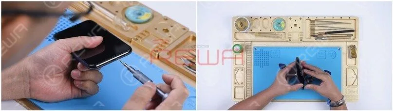
    Retirer les deux vis à pentalobe situées sur le bord inférieur.

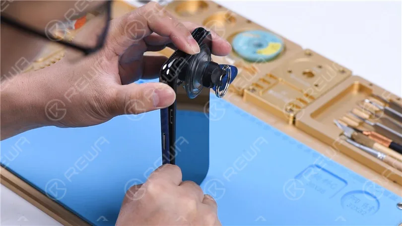
    Tirez sur le petit nœud de la ventouse pour soulever l'écran.

    Insérez une pièce de préhension lorsqu'il y a un espace et faites-la glisser le long de l'espace.
    Comment réparer l'iPhone 11 qui ne s'allume pas avec un courant important

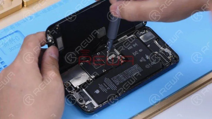
    Une fois l'écran soulevé, retirez les couvercles de protection.

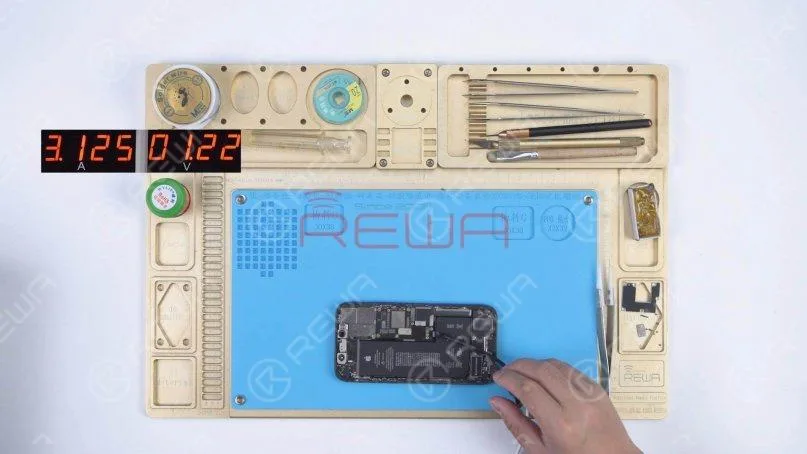
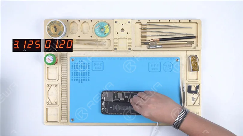
    Déconnectez la batterie et retirez l'écran. Branchez la carte mère à l'aide du câble d'alimentation.

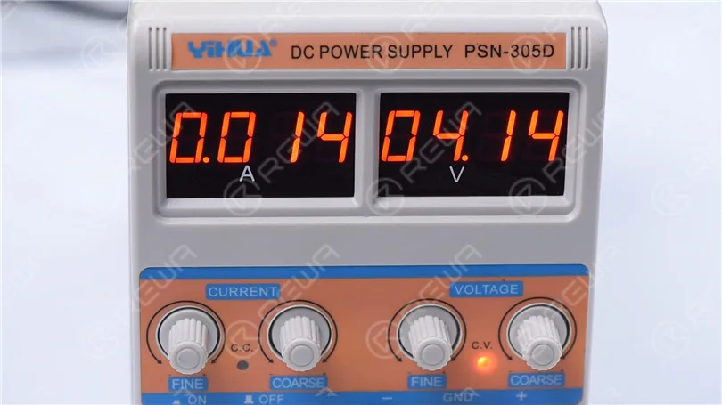
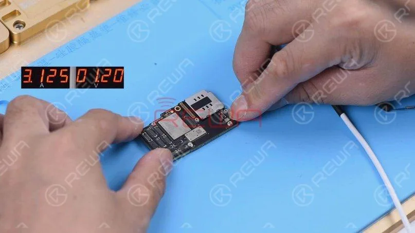
    L'ampèremètre indique un courant important de 3,1A.
    Comment réparer l'iPhone 11 qui ne s'allume pas avec un courant important

    Déconnectez les câbles flexibles. Retirer le plateau de la carte SIM.

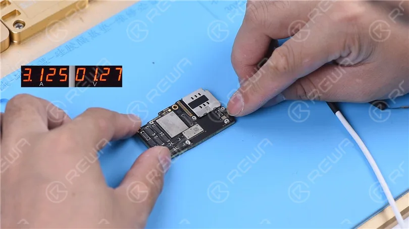
    Détachez la carte mère. Connecter à nouveau la carte mère avec le câble d'alimentation.

    L'ampèremètre indique toujours un courant important de 3,1A.

    Cela indique que le courant important n'a rien à voir avec d'autres câbles flexibles.

    Le problème se situe au niveau de la carte mère.
    Comment réparer l'iPhone 11 qui ne s'allume pas avec un courant important

    Mesure en mode diode

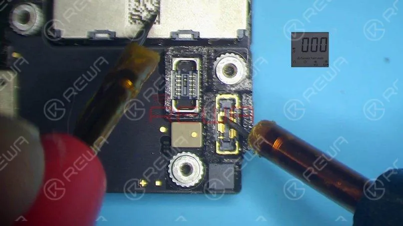
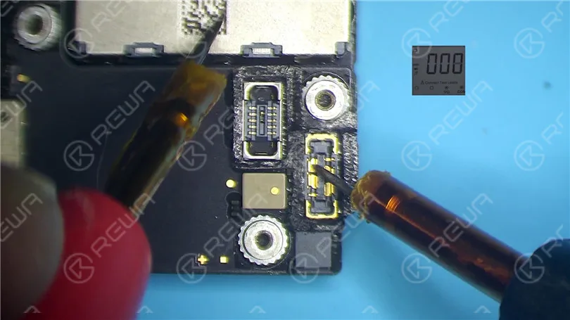
    Effectuez une mesure en mode diode de la broche 1 du J7010 du connecteur de la batterie.

    La valeur de la diode est de 0. Cela indique que le circuit d'alimentation principal est court-circuité à la terre.

    Étant donné que le circuit alimente simultanément la carte logique et la carte signal, nous devons séparer la carte mère pour localiser la panne.
    Comment réparer l'iPhone 11 qui ne s'allume pas avec un courant important

    Séparation de la carte mère

    Retirer la mousse de la carte mère.

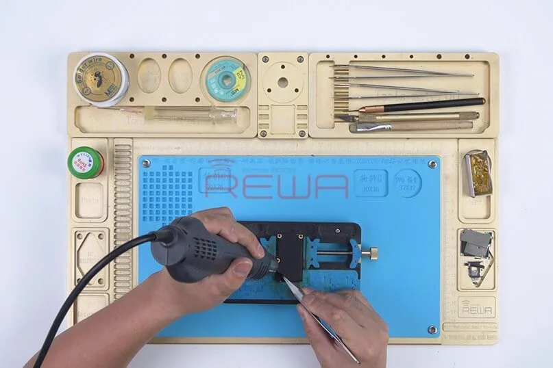
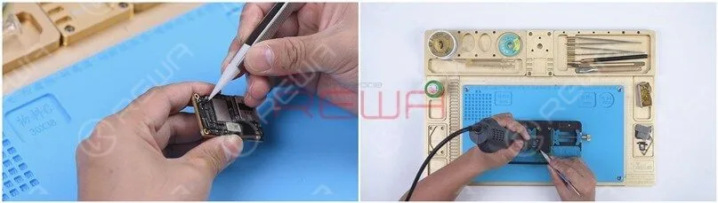
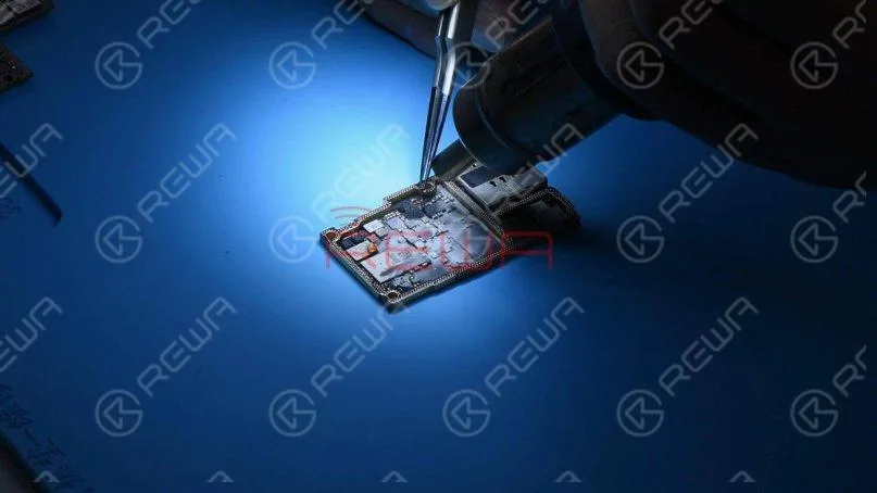
    Chauffer l'arrière de la carte mère avec un pistolet à air chaud à 240 degrés Celsius.

    Retirer le papier de protection.

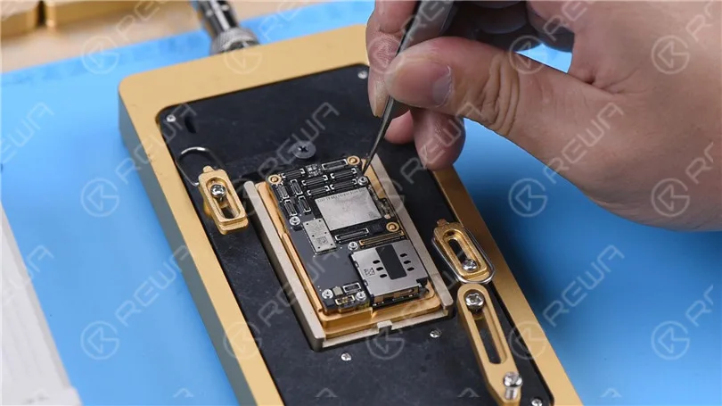
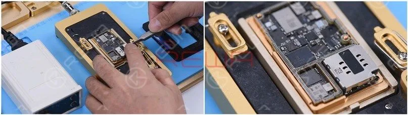
    Placez la carte mère sur le Plate-forme de chauffage.

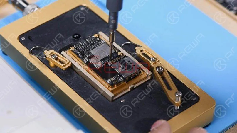
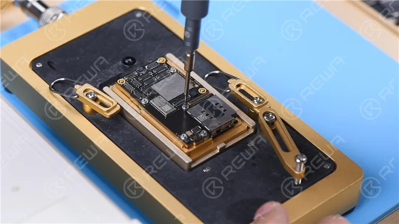
    Pour faciliter le retrait de la carte logique après la séparation, enfoncez une vis sur la carte logique.

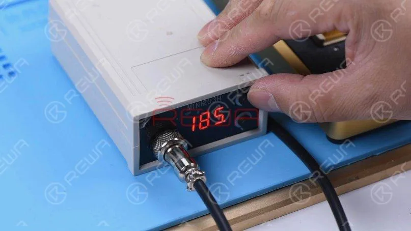
    Réglez la température de la plate-forme de chauffage à 185 degrés Celsius.

    Serrez la vis pour retirer la carte logique lorsque la température a atteint 185 degrés Celsius. Retirez la carte de signalisation.
    Comment réparer l'iPhone 11 qui ne s'allume pas avec un courant important
    Comment réparer l'iPhone 11 qui ne s'allume pas avec un courant important

    Mesure en mode diode

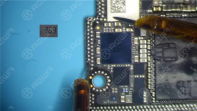
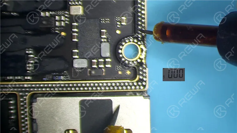
    Effectuez une mesure en mode diode sur la broche 286 de la carte de signalisation. La valeur de la diode est de 0.

    Cela indique que l'alimentation principale de la carte de signalisation est court-circuitée à la terre.

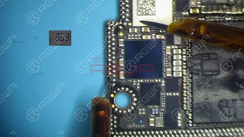
    Mesurer la broche 286 sur la carte logique.

    La valeur de la diode est de 363, ce qui signifie que la carte logique est normale.
    Comment réparer l'iPhone 11 qui ne s'allume pas avec un courant important
    Comment réparer l'iPhone 11 qui ne s'allume pas avec un courant important

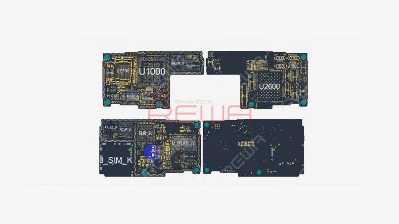
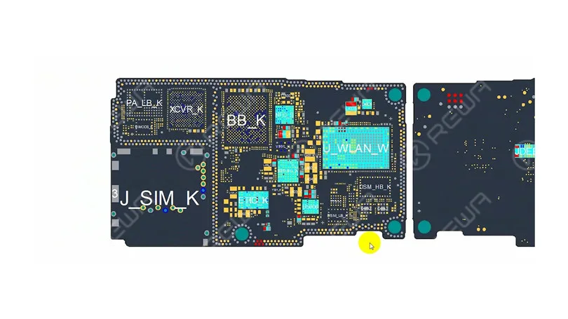
    Ouvrez l'image bitmap. Nous pouvons voir qu'il y a de nombreux composants associés sur le circuit d'alimentation principal.
    Comment réparer l'iPhone 11 qui ne s'allume pas avec un courant important

    Détection de colophane

    Ensuite, nous devons localiser le composant défectueux à l'aide d'un détecteur de colophane.

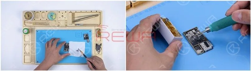
    Enlever la graisse thermique à l'aide d'un couteau à sculpter.

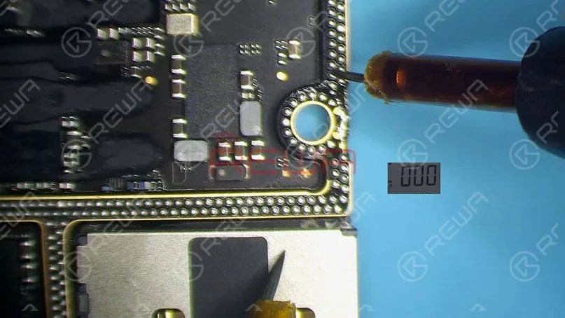
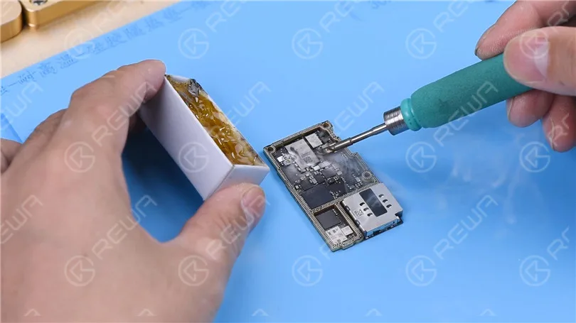
    Tremper la colophane dans un fer à souder à 365 degrés Celsius.

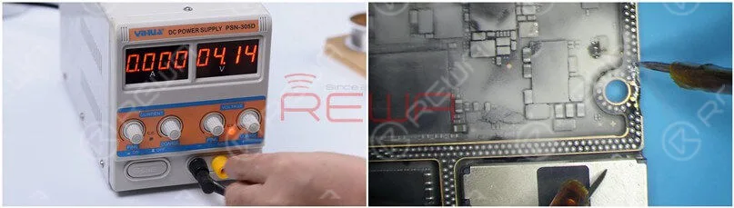
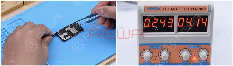
    Fumez de la colophane sur le tableau de signalisation. Régler l'alimentation en courant continu à 4,1 V.

    Connecter l'anode positive et l'anode négative de l'alimentation en courant continu avec des sondes de multimètre.

    Connecter la sonde noire à la terre.

    Connectez la sonde rouge à la broche 286 du tableau de signalisation.

    Nous pouvons voir que la colophane sur C1200 K a fondu. Cela indique que le condensateur est endommagé.
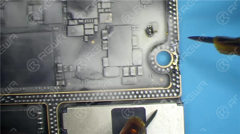
    Comment réparer l'iPhone 11 qui ne s'allume pas avec un courant important
    Comment réparer l'iPhone 11 qui ne s'allume pas avec un courant important

    Nous le chauffons ensuite avec un pistolet à air chaud à 350 degrés Celsius. Retirez le condensateur à l'aide d'une pince à épiler.
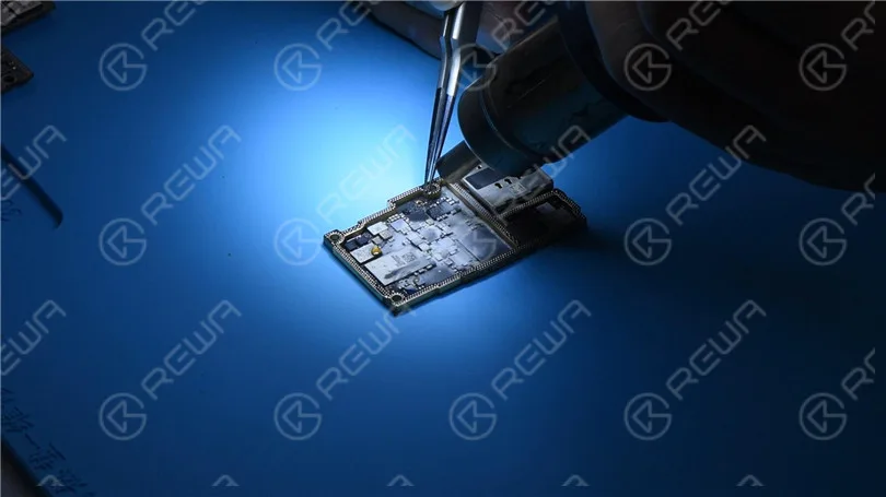
    Comment réparer l'iPhone 11 qui ne s'allume pas avec un courant important

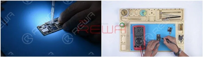
    Nettoyez la colophane sur la carte de signal avec du PCB Cleaner. Effectuez une deuxième mesure en mode diode. La valeur de la diode revient à une valeur normale de 327.
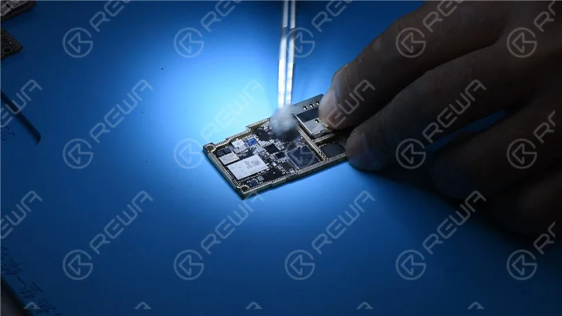
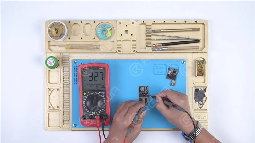
    Comment réparer l'iPhone 11 qui ne s'allume pas avec un courant important
    Comment réparer l'iPhone 11 qui ne s'allume pas avec un courant important

    Recombinaison de la carte mère

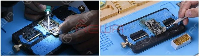
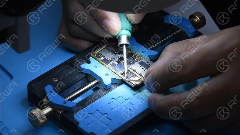
    Enduire de colophane le fer à souder et la mèche à souder à 365 degrés Celsius pour enlever l'étain sur la plaque de liaison.

    Nettoyez la carte de signal avec du PCB Cleaner. Retirez l'étain et nettoyez la carte logique avec la même méthode.
    Comment réparer l'iPhone 11 qui ne s'allume pas avec un courant important

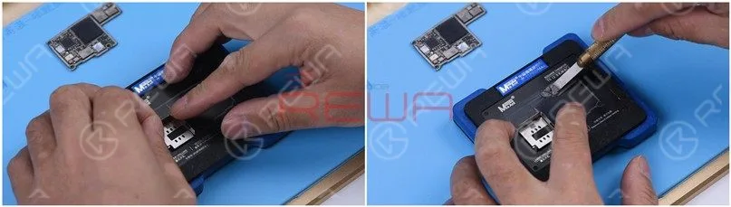
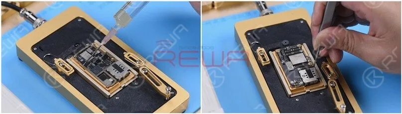
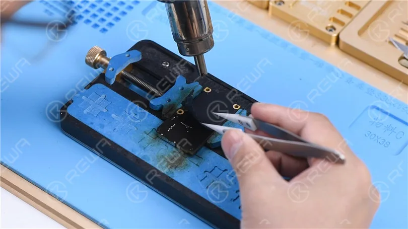
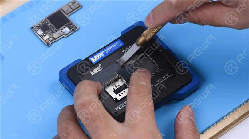
    Fixez le tableau de signalisation à la plate-forme de reballage.

    Mettez le pochoir de rebouchage en place. Pour éviter que la pâte à braser ne coule dans les fentes de la carte mère, insérez une plaque métallique.

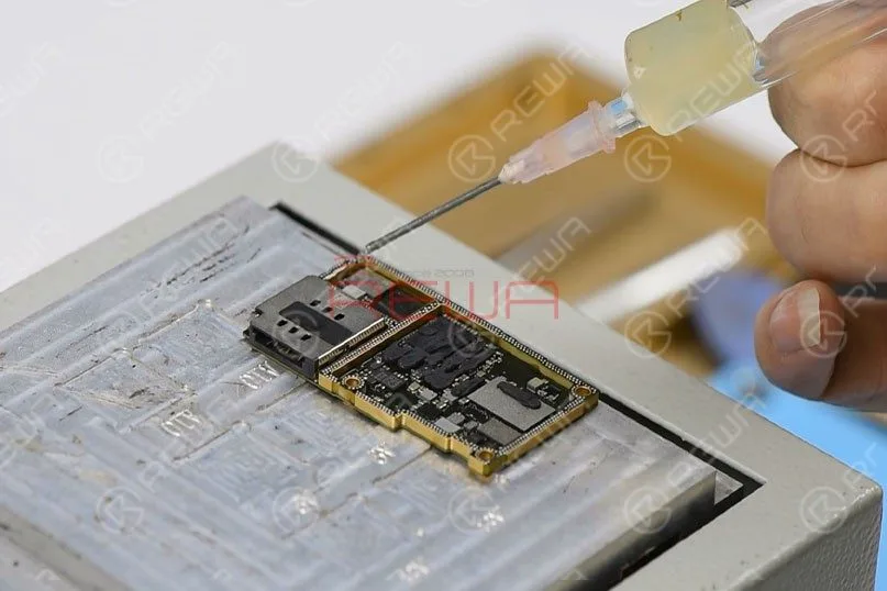
    Appliquer une couche de pâte à braser basse température.

    Retirer le pochoir de rebouclage.
    Comment réparer l'iPhone 11 qui ne s'allume pas avec un courant important

    Placez le tableau de signalisation sur la plate-forme chauffante à 185 degrés Celsius pour le chauffer.

    Une fois les billes de soudure formées, éteignez l'appareil et laissez refroidir la carte mère pendant 5 minutes.

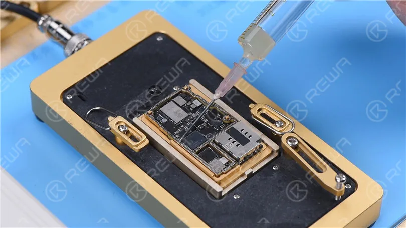
    Appliquer un peu de Paste Flux.

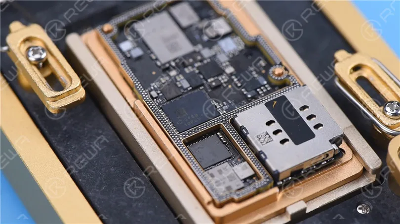
    Alignez la carte logique avec la carte de signalisation.

    Maintenir le chauffage sur la plate-forme chauffante à 185 degrés Celsius.

    Lorsque la température atteint 185 degrés Celsius, continuer à chauffer pendant 1 minute.

    Cette étape permet de s'assurer que la carte logique et la carte de signalisation s'emboîtent parfaitement.
    Comment réparer l'iPhone 11 qui ne s'allume pas avec un courant important
    Comment réparer l'iPhone 11 qui ne s'allume pas avec un courant important
    Comment réparer l'iPhone 11 qui ne s'allume pas avec un courant important

    Essais

    Connecter la carte mère avec le câble d'alimentation.

    Court-circuiter la masse de la broche 12 du J7700. Le courant de démarrage devient normal.

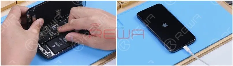
    Mettez la carte mère sur le téléphone.

    Connecter les câbles flexibles. Connecter l'écran et la batterie.

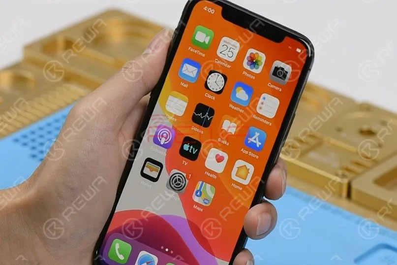
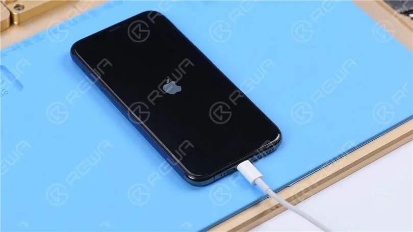
    Parce que la batterie est déchargée. Branchez le câble de chargement et le téléphone s'allume normalement.
    Comment réparer l'iPhone 11 qui ne s'allume pas avec un courant important
    Comment réparer l'iPhone 11 qui ne s'allume pas avec un courant important
  • How to Fix an iPhone 11 Pro Won’t Turn On

    How to Fix an iPhone 11 Pro Won’t Turn On

    Having trouble with your iPhone 11 Pro refusing to turn on? Don’t worry, we’ve got your back! In this comprehensive guide, we’ll walk you through some practical and effective solutions to fix this frustrating issue.

    Step 1: Disassemble and test

    Remove the two pentalobe screws at the bottom edge and lift the screen.
    Remove the two pentalobe screws at the bottom edge and lift the screen.

    After the screen is lifted, take the shielding covers off, disconnect the battery, and remove the screen.
    After the screen is lifted, take the shielding covers off, disconnect the battery, and remove the screen.

    Connect the motherboard with the Power Cable. The ammeter shows a large current of 3.1A.
    Connect the motherboard with the Power Cable. The ammeter shows a large current of 3.1A.

    Detach the motherboard and connect the motherboard with the Power Cable again. The ammeter still shows a large current of 3.1A.
    Detach the motherboard and connect the motherboard with the Power Cable again. The ammeter still shows a large current of 3.1A.

    It indicates that the large current has nothing to do with other flex cables. The fault is on the motherboard.

    Step 2: Run diode mode measurement

    Run diode mode measurement of pin 1 on the J7010 of the battery connector. The diode value is 0 which indicates that the main power supply circuit is shorted to the ground.

    Run diode mode measurement of pin 1 on the J7010 of the battery connector. The diode value is 0 which indicates that the main power supply circuit is shorted to the ground.

    Étant donné que le circuit alimente simultanément la carte logique et la carte signal, nous devons séparer la carte mère pour localiser la panne.

    Step 3: Motherboard separation

    Remove foam on the motherboard. Then heat the back of the motherboard with Pistolet à air chaud at 240℃ to remove the shielding paper.
    Remove foam on the motherboard. Then heat the back of the motherboard with Hot Air Gun at 240℃ to remove the shielding paper.

    Placez la carte mère sur le Plate-forme de chauffage. To make it easier to remove the logic board after separation, drive a screw on the logic board.
    Put the motherboard on the Heating Platform. To make it easier to remove the logic board after separation, drive a screw on the logic board.

    Set the temperature of the Heating Platform to 185℃.

    Set the temperature of the Heating Platform to 185℃.

    Clamp the screw to remove the logic board when the temperature has risen to 185℃. Lastly, remove the signal board.
    Clamp the screw to remove the logic board when the temperature has risen to 185℃. Lastly, remove the signal board.

    Step 4: Run diode mode measurement again

    Run diode mode measurement of pin 286 on the signal board. The diode value is 0. It suggests that the main power supply of the signal board is shorted to the ground.

    Run diode mode measurement of pin 286 on the signal board. The diode value is 0. It suggests that the main power supply of the signal board is shorted to the ground.

    Measure pin 286 on the logic board. The diode value is 363 which means the logic board is normal.

    Measure pin 286 on the logic board. The diode value is 363 which means the logic board is normal.

    Open the bitmap. We can see there are many associated components on the main power supply circuit.

    Ouvrez l'image bitmap. Nous pouvons voir qu'il y a de nombreux composants associés sur le circuit d'alimentation principal.

    Step 5: Rosin detecting to locate the fault

    Next, we need to locate the faulty component with rosin detecting.Remove thermal grease with a Sculpture Knife. Then dip rosin with Fer à souder at 365℃ and smoke rosin on the signal board.

    Next, we need to locate the faulty component with rosin detecting.Remove thermal grease with a Sculpture Knife. Then dip rosin with Soldering Iron at 365℃ and smoke rosin on the signal board.

    Set the direct current supply to 4.1V. Connect the positive and negative anode of the direct current supply with multimeter probes. Connect the black probe to the ground and connect the red probe to pin 286 on the signal board. We can see rosin on C1200_K has melted. It indicates that the capacitor is damaged.

    Set the direct current supply to 4.1V. Connect the positive and negative anode of the direct current supply with multimeter probes. Connect the black probe to the ground and connect the red probe to pin 286 on the signal board. We can see rosin on C1200_K has melted. It indicates that the capacitor is damaged.

    Step 6: Eliminate the fault and restore the motherboard

    Then we heat the damaged capacitor with Hot Air Gun at 350℃ and remove it with tweezers.

    Then we heat the damaged capacitor with Hot Air Gun at 350℃ and remove it with tweezers.

    Nettoyez la colophane sur la carte de signal avec du PCB Cleaner. Effectuez une deuxième mesure en mode diode. La valeur de la diode revient à une valeur normale de 327.

    Nettoyez la colophane sur la carte de signal avec du PCB Cleaner. Effectuez une deuxième mesure en mode diode. La valeur de la diode revient à une valeur normale de 327.

    Smear rosin with Soldering Iron and solder wick at 365℃ to remove tin on the bonding pad. Clean the signal board with PCB Cleaner.

    Smear rosin with Soldering Iron and solder wick at 365℃ to remove tin on the bonding pad. Clean the signal board with PCB Cleaner.

    Remove tin and clean the logic board with the same method.Attach the signal board to the Reballing Platform and put the Reballing Stencil in position. To prevent the solder paste from flowing into the motherboard crevices, insert a metal plate. Apply a layer of low-temperature Pâte à braser. 

    Remove tin and clean the logic board with the same method.Attach the signal board to the Reballing Platform and put the Reballing Stencil in position. To prevent the solder paste from flowing into the motherboard crevices, insert a metal plate. Apply a layer of low-temperature Solder Paste.

    Remove the Reballing Stencil and put the signal board on the Heating Platform at 185℃ to heat. After the solder balls are formed, turn the power off and cool the motherboard for 5 minutes.

    Remove the Reballing Stencil and put the signal board on the Heating Platform at 185℃ to heat. After the solder balls are formed, turn the power off and cool the motherboard for 5 minutes.

    Appliquer quelques Flux en pâte and align the logic board with the signal board. Keep heating on the Heating Platform at 185℃. When the temperature reaches 185℃, keep heating for 1 minute.This step is to ensure that the logic board and the signal board fit closely.

    Apply some Paste Flux and align the logic board with the signal board. Keep heating on the Heating Platform at 185℃. When the temperature reaches 185℃, keep heating for 1 minute.This step is to ensure that the logic board and the signal board fit closely.Step 7: Test and assemble

    Connect the motherboard with the Power Cable and short to the ground of the J7700 pin 12. The boot current becomes normal.

    Connect the motherboard with the Power Cable and short to the ground of the J7700 pin 12. The boot current becomes normal.

    Put the motherboard on the phone. Connect the flex cables, screen, and battery. Because the battery is dead, plug the charging cable and the phone turns on normally.

    Put the motherboard on the phone. Connect the flex cables, screen, and battery. Because the battery is dead, plug the charging cable and the phone turns on normally.

    Conclusion :

    iPhone 11 Pro won’t turn on with a large current. We found that the main power supply was shorted to the ground through measuring the battery connector. The fault was found to be on the signal board after separation. Rosin detecting showed us that C1200_K was damaged. After removing C1200_K, the fault was cleared.

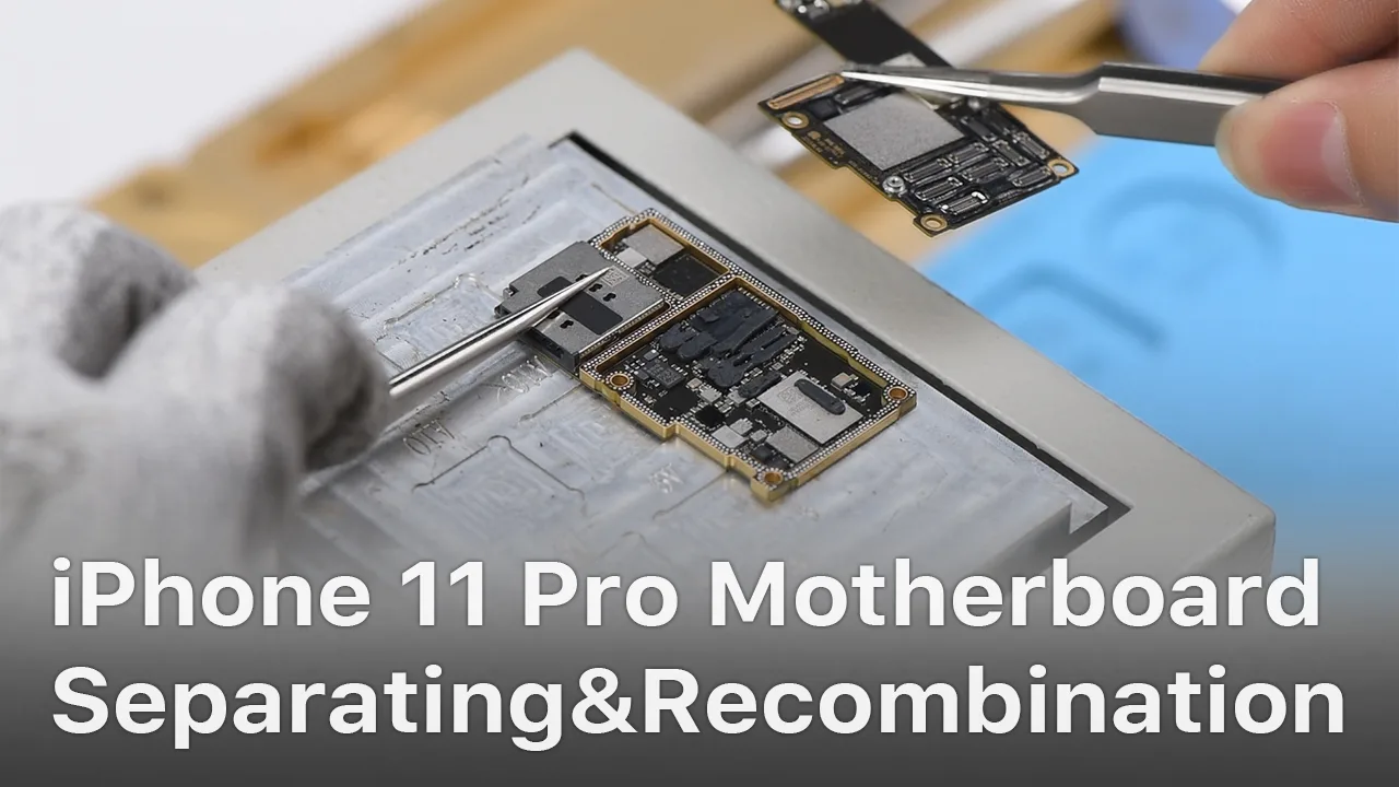
  • Séparation de la carte mère de l'iPhone 11 Pro

    Séparation de la carte mère de l'iPhone 11 Pro

    Comme nous le savons tous, les nouvelles séries d'iPhone ont subi des changements considérables, tant à l'intérieur qu'à l'extérieur.

    En particulier sur la carte mère.

    Comment ces changements affecteront-ils le secteur de la réparation ?

    Cela rendra-t-il la réparation par un tiers plus difficile ou plus facile ?

    Suivez dès aujourd'hui notre blog sur la séparation et la recombinaison de la carte mère de l'iPhone 11 Pro et trouvez la réponse par vous-même.

    Séparation de la carte mère de l'iPhone 11 Pro

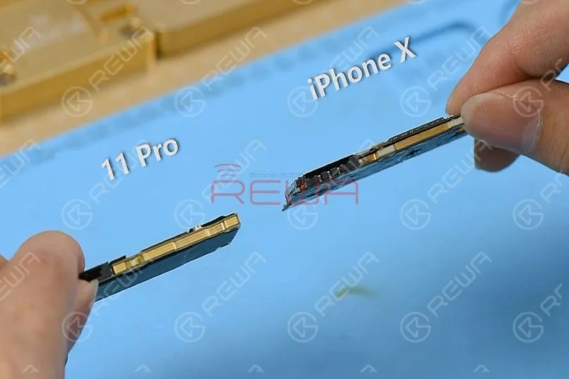
    Par rapport à la série iPhone X, la carte mère de l'iPhone 11 Pro est plus petite avec un réseau de composants beaucoup plus dense.

    Il est également plus épais.

    Le verso est recouvert de couches de matériau de transfert thermique en graphite.

    Il peut dissiper efficacement la chaleur générée par la carte mère.
    Par rapport à la série iPhone X, la carte mère de l'iPhone 11 Pro est plus petite avec un réseau de composants beaucoup plus dense. Elle est également plus épaisse. Il y a des couches de matériau de transfert thermique en graphite à l'arrière. Il peut dissiper efficacement la chaleur générée par la carte mère.

    Étape 1

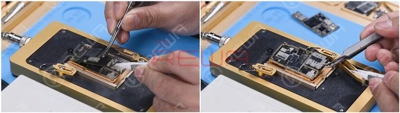
    Retirez d'abord le matériau de transfert thermique en graphite à l'aide d'une pince à épiler.

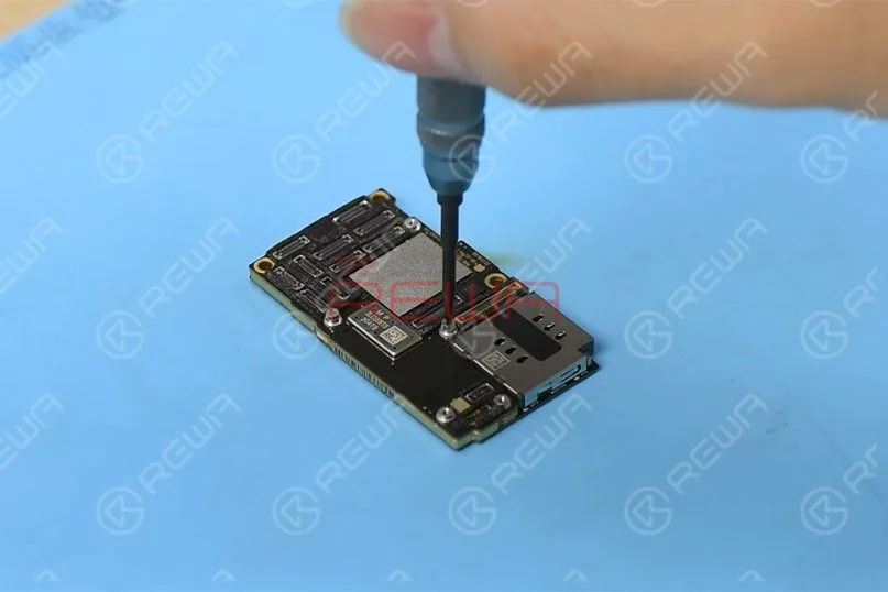
    Pour recombiner les deux couches sans refaire la boule après la séparation, insérons deux vis dans les trous réservés à cet effet sur la carte mère.

    Retirez d'abord le matériau de transfert thermique en graphite à l'aide d'une pince à épiler. Pour recombiner les deux couches sans refaire la boule après la séparation, insérons deux vis dans les trous réservés à cet effet sur la carte mère.

    Étape 2

    Régler la température de la plate-forme de chauffage à 170℃.

    Lorsque la température de la plate-forme atteint 170℃, placer la carte mère sur la plate-forme pour chauffer pendant 3 minutes.

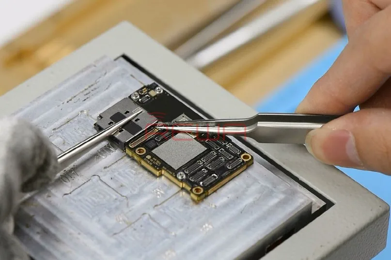
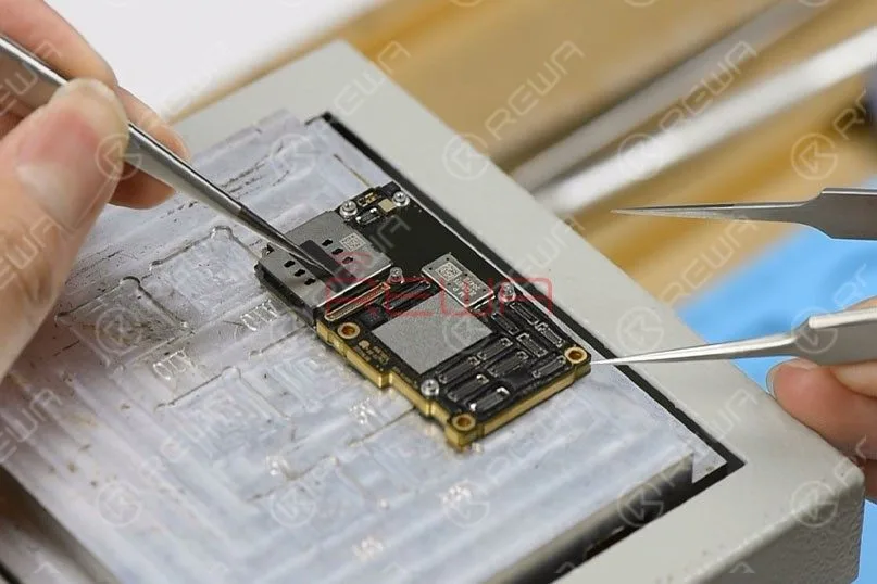
    Appuyez sur le lecteur de carte SIM à l'aide de la pince et poussez légèrement la couche supérieure à l'aide d'une autre pince.
    Régler la température de la plateforme chauffante à 170℃. Lorsque la température de la plateforme atteint 170℃, placer la carte mère sur la plateforme pour la chauffer pendant 3 minutes. Appuyer sur le lecteur de carte SIM avec la pince et pousser légèrement la couche supérieure avec une autre pince.

    Étape 3

    Lorsque les billes de soudure du circuit imprimé du troisième espace commencent à fondre, serrez les vis insérées dans les trous de vis à l'aide d'une pince à épiler et saisissez la couche supérieure à la verticale à l'aide d'une pince à épiler.

    Conseils : ne secouez pas les pinces lorsque vous prenez la couche supérieure.

    Le PCB du troisième espace pourrait être bloqué par des problèmes de pontage et le travail de recombinaison serait également affecté.

    Continuer à ramasser la couche inférieure.

    Structure de la carte mère de l'iPhone 11 Pro

    Commençons par la structure de la carte mère.

    La couche supérieure

    Structure de la carte mère de l'iPhone 11 Pro

    A.Composé thermique

    Le CPU et les zones autour du CPU sont recouverts d'une grande quantité de composé thermique pour dissiper la chaleur générée par le CPU A13.

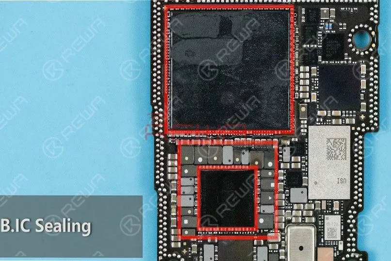
    B.Scellement IC

    L'unité centrale, la PMU et les inducteurs autour de la PMU sont scellés avec de l'adhésif, ce qui rend les réparations plus difficiles dans une certaine mesure.

    C.Réseau dense de composants autour de la PMU

    Le brasage/dessoudage de la PMU requiert un travail professionnel.

    D.IC USB

    Contrairement à la série iPhone X, le circuit intégré USB de l'iPhone 11 Pro n'a pas été scellé avec de l'adhésif, et il est loin de l'unité centrale.

    Par conséquent, la difficulté des réparations relatives au CI USB est relativement réduite

    Contrairement à la série iPhone X, le processeur A13 de l'iPhone 11 Pro n'est pas situé juste à l'arrière de la puce flash NAND.

    Cela permet de réduire la possibilité de pontage du CPU lors du soudage/dessoudage de la puce flash NAND.

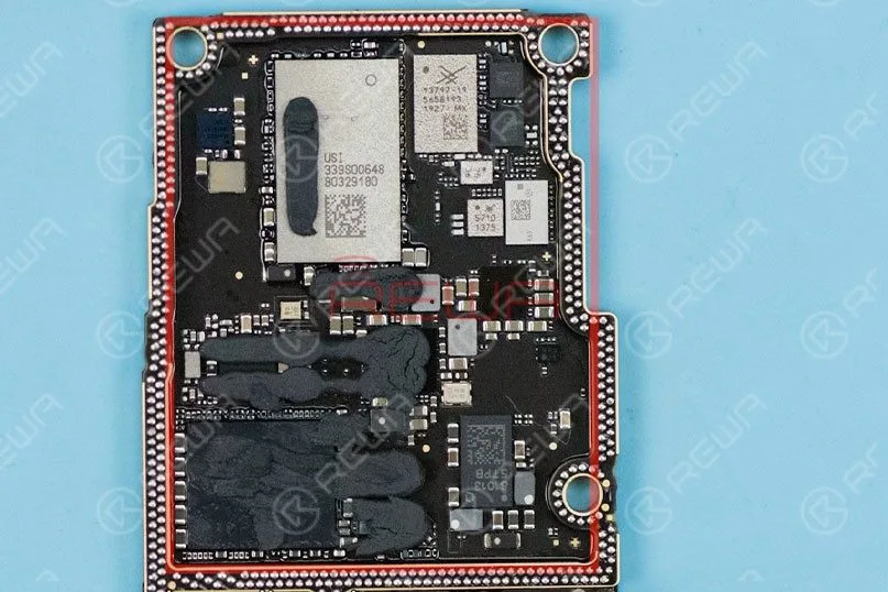
    La couche inférieure

    La couche inférieure

    A. Contrairement à la série iPhone X, la couche inférieure de l'iPhone 11 Pro est dotée d'un réseau de composants dispersifs. Par conséquent, la difficulté des réparations pertinentes pour le signal est également réduite.

    B. Contrairement à la série iPhone X, le lecteur de carte SIM de l'iPhone 11 Pro est indépendant des autres composants. Nous n'avons pas besoin de retirer le lecteur de carte SIM lorsque nous travaillons sur des réparations pertinentes pour le signal.

    Recombinaison de la carte mère de l'iPhone 11 Pro sans reconditionnement

    Régler la température de la plate-forme de chauffage à 170℃.

    Lorsque la température de la plate-forme atteint 170℃, placer la couche inférieure sur la plate-forme pour la chauffer pendant 10 secondes.

    Appliquer uniformément un peu de Paste Flux sur la carte de circuit imprimé du troisième espace.

    Mettez la couche supérieure en place et faites-la chauffer pendant environ 5 minutes.
    Régler la température de la plate-forme chauffante à 170℃. Lorsque la température de la plate-forme atteint 170℃, placer la couche inférieure sur la plate-forme pour chauffer pendant 10 secondes. Appliquer uniformément du flux de pâte sur le circuit imprimé du troisième espace. Obtenir la couche supérieure en position et chauffer pendant environ 5 minutes.

    Ensuite, appuyez sur le lecteur de carte SIM à l'aide de la pince à épiler et poussez légèrement la couche supérieure à l'aide d'une autre pince à épiler.

    Si la couche supérieure revient automatiquement à la position précédente, le processus de brasage est terminé.

    Test

    Nous pouvons maintenant assembler le téléphone et le tester.

    Test Nous pouvons maintenant assembler le téléphone et le tester.

    Installez la carte mère et l'écran et connectez la batterie.

    Appuyez sur le bouton d'alimentation pour allumer le téléphone.

    Le téléphone s'allume normalement.
    Test de fonctionnement. Tout se passe bien.

    Résumé

    La séparation&recombinaison de la carte mère de l'iPhone 11 Pro montre que la carte mère est plus petite et plus carrée.

    Par rapport à la série iPhone X, il ne sera pas facilement endommagé par des forces extérieures.

    L'intégration poussée de la carte mère signifie également qu'un travail plus professionnel est nécessaire.

    Dans l'ensemble, la difficulté des réparations de la carte mère de l'iPhone 11 Pro est réduite.

    Outils et pièces détachées

    Vous pouvez également visiter Chaîne Youtube de REWA pour consulter notre vidéo sur la séparation et la recombinaison de la carte mère de l'iPhone 11 Pro.

  • Réparation de la vitre arrière de l'iPhone 11 Pro

    Réparation de la vitre arrière de l'iPhone 11 Pro

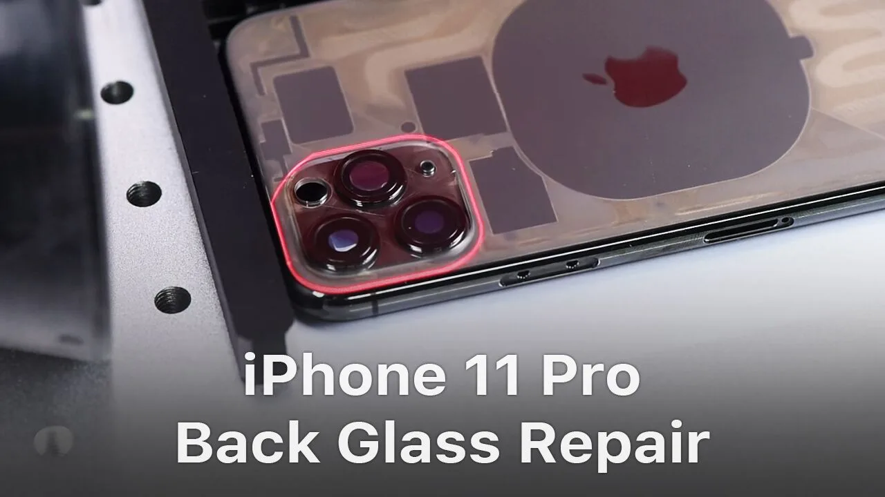
    As the most powerful and most advanced iPhone that Apple has ever built, iPhone 11 Pro  is made of a surgical grade stainless steel its back is a single piece of machine glass with an optical PVD coating, adding to the difficulty of repair.

    What’s more, the arrangement of rear cameras of iPhone 11 Pro also greatly increases the difficulty of back glass repair.

    REWA LAB tried different solutions (heating with the Hot Air Gun, separating with the dispergator/freeze assistance) and we were unable to remove the glass around the triple-lens camera safely and efficiently.

    Check our detailed operation on iPhone 11 Pro back glass repair and hope we can enlighten you somehow.

    Scan The 11 Pro Back Glass With Laser

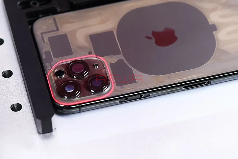
    First of all, place the iPhone 11 Pro back glass under the probe for focusing.

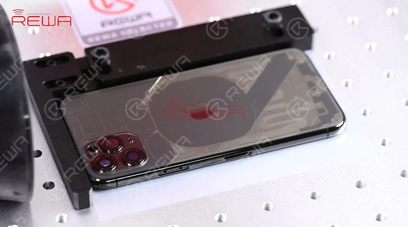
    Then place the iPhone 11 Pro back glass on the operating panel.

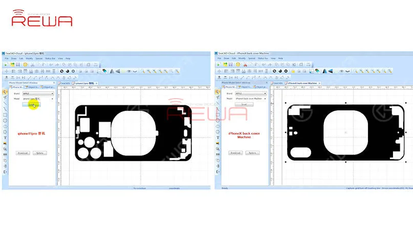
    Choose ‘iPhone 11 Pro’ from the model list and click ‘Load’ to load the drawing.

    The black area on the drawing is the area to be scanned, And the white area is the area to be retained.

    Tips: Compare the two drawings and we can see that different from iPhone X, there are more areas the laser should keep away from when scanning iPhone 11 Pro.
    First of all, place the iPhone 11 Pro back glass under the probe for focusing. Then place the iPhone 11 Pro back glass on the operating panel.   Choose ‘iPhone 11 Pro’ from the model list and click ‘Load’ to load the drawing.   The black area on the drawing is the area to be scanned, And the white area is the area to be retained.   Tips: Compare the two drawings and we can see that different from iPhone X, there are more areas the laser should keep away from when scanning iPhone 11 Pro.

    After loading the drawing of iPhone 11 Pro, adjust the laser light scanning area on the back glass.

    Once finished, get the parameter set and click ‘Mark’ to scan the back glass with the laser light.

    The back glass becomes transparent after laser scanning.
    After loading the drawing of iPhone 11 Pro, adjust the laser light scanning area on the back glass. Once finished, get the parameter set and click ‘Mark’ to scan the back glass with the laser light. The back glass becomes transparent after laser scanning.

    Scan The Glass Around The Triple-lens Camera With Laser

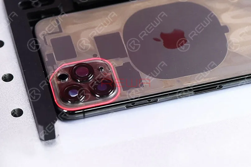
    As you can see, the glass around the triple-lens camera is relatively thick.

    The laser light scanning didn’t work well with the area here.

    After several attempts and experiments, REWA LAB successfully completed a specialized drawing for the triple-lens camera area.

    Scan the triple-lens camera area again with the laser with the help of the drawing.

    The glass around the triple-lens camera also becomes transparent after the second laser scanning.
    Scan the triple-lens camera area again with the laser with the help of the drawing. The glass around the triple-lens camera also becomes transparent after the second laser scanning.

    Separate The Back Glass From The Mid-frame 

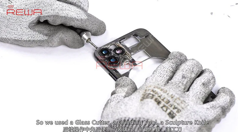
    Now we need to separate the back glass from the mid-frame. The scanned back glass can be separated easily. However, the glass around the triple-lens camera needs further operation. Our commonly used tools failed to remove the glass here, so we used a glass cutter, a grinding tool, a Sculpture Knife and a Cutting Nipper to remove the glass around the triple-lens camera. At the last, once completed, remove residual black adhesive with the Laser Machine.
    Now we need to separate the back glass from the mid-frame. The scanned back glass can be separated easily. However, the glass around the triple-lens camera needs further operation. Our commonly used tools failed to remove the glass here, so we used a glass cutter, a grinding tool, a Sculpture Knife and a Cutting Nipper to remove the glass around the triple-lens camera. At the last, once completed, remove residual black adhesive with the Laser Machine.

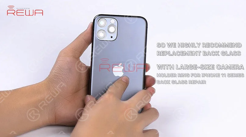
    The camera holder ring of iPhone 11 series is harder and comes with thick inside walls, adding to the difficulty of polishing.

    Meanwhile, the camera lens can also be easily damaged during polishing.

    So we highly recommend replacement back glass with a big camera hole for iPhone 11 series back glass repair.
    The camera holder ring of iPhone 11 series is harder and comes with thick inside walls, adding to the difficulty of polishing. Meanwhile, the camera lens can also be easily damaged during polishing. So we highly recommend replacement back glass with a big camera hole for iPhone 11 series back glass repair.

    Due to the special arrangement of the three cameras of iPhone 11 Pro, the space between the three cameras is also narrow, adding to the difficulty of back glass separating.

    Therefore, the Laser Machine may be the safest and most efficient solution for iPhone 11 Pro back glass repair.

    For more details about the back glass repair of iPhone 11 Pro, please check the video below. You can also visit Chaîne YouTube de REWA for more videos about iPhone 11 series.

    REWA LAB will work hard to provide a better solution for iPhone 11 Pro back glass repair.

    The replacement parts of iPhone 11 series are also coming soon, please stay tuned to Boutique en ligne REWA.

  • Réparation de la vitre arrière de l'iPhone 11 Pro

    Réparation de la vitre arrière de l'iPhone 11 Pro

    Les caméras arrière de la série iPhone 11 augmentent considérablement la difficulté de la réparation de la vitre arrière. REWA LAB a testé différentes solutions (chauffage au pistolet à air chaud, séparation avec le disperseur/assistance par congélation) et nous n'avons pas été en mesure de retirer la vitre autour de la caméra à triple objectif en toute sécurité et efficacité. Regardez notre vidéo de réparation de la vitre arrière de l'iPhone 11 Pro maintenant et nous espérons pouvoir vous éclairer d'une manière ou d'une autre. Veuillez nous faire part de vos réflexions sur ce sujet dans les commentaires ci-dessous.

    Outils et pièces utilisés dans cette vidéo de rénovation de la vitre arrière de l'iPhone 11 Pro :


  • Transformer l'iPhone 11 Pro en iPhone 11 Pro Max

    Transformer l'iPhone 11 Pro en iPhone 11 Pro Max

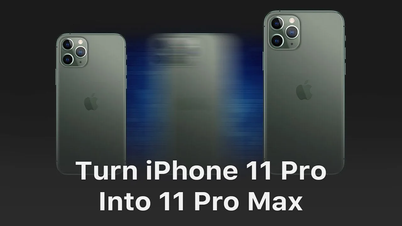
    Can iPhone 11 Pro possibly be turned into iPhone 11 Pro Max? It is actually theoretically possible. With pins of the two phones’ display connector and touch connector functioning almost the same, we can turn an iPhone 11 Pro into an iPhone 11 Pro Max by changing board ID resistors. Check our video now and find out how we finally made it.

    Warm Tips: This video is made for technique sharing only. For those who have no professional skills, please look before you leap.

    Tools & Parts used to separate iPhone 11 Pro:

  • iPhone 11 Pro Motherboard Separating & Recombination

    iPhone 11 Pro Motherboard Separating & Recombination

    iPhone new series have undergone considerable changes on both inside and outside. Especially on the motherboard. How will these changes affect the repair industry? Will it make third-party repair harder or easier? Follow our iPhone 11 Pro motherboard separation&recombination video today and find the answer by yourself.

    Tools & Parts used to separate iPhone 11 Pro: