Étiquette : iphone 11 pro max

  • Réparation de l'écran noir et du problème de démarrage de l'iPhone 11 Pro Max

    Réparation de l'écran noir et du problème de démarrage de l'iPhone 11 Pro Max

    The iPhone 11 Pro Max is a powerful device, but even the best smartphones can run into issues. One common problem is when the screen suddenly turns black, and the phone refuses to boot. In this guide, we’ll take you through the step-by-step process of diagnosing and repairing this issue. Whether you’re a professional technician or a DIY repair enthusiast, this article will help you troubleshoot and resolve the no-boot problem on your iPhone 11 Pro Max.
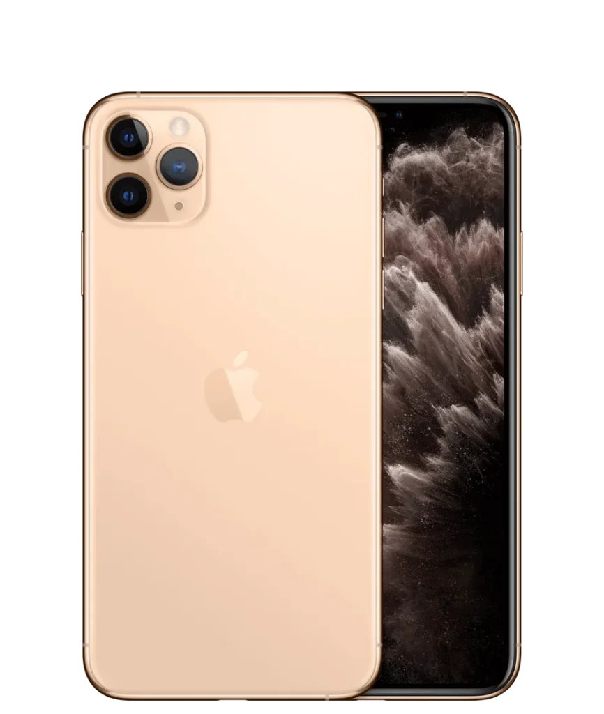
    iphone 11 pro max

    Détails du téléphone

    Modèle : iPhone 11 Pro Max

    Annoncé : 2019, September 10

    Phénomène de défaut

    The iPhone 11 Pro Max suddenly experienced a black screen and could not boot during regular use.

    Dépannage

    1 : Évaluation initiale
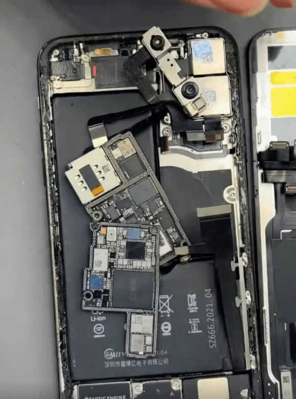
    iphone 11 pro max black screen no boot issue repair cannot start up
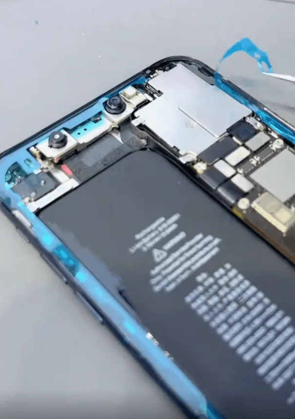
    • The phone was previously repaired by another technician. Upon receiving it, the motherboard was already separated. A visual inspection revealed no signs of physical damage or water exposure.

    2: Testing the Motherboard
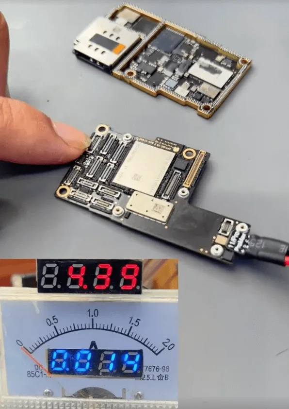
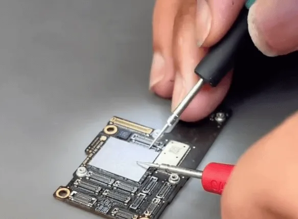
    • Connect the upper layer of the motherboard to a DC power supply and attempt to trigger the boot process using tweezers.
    • The boot current is fixed at 14mA, which suggests a problem with the NAND chip or CPU, particularly with the power supply rails.

    3: Diagnosing the Power Supply Issue
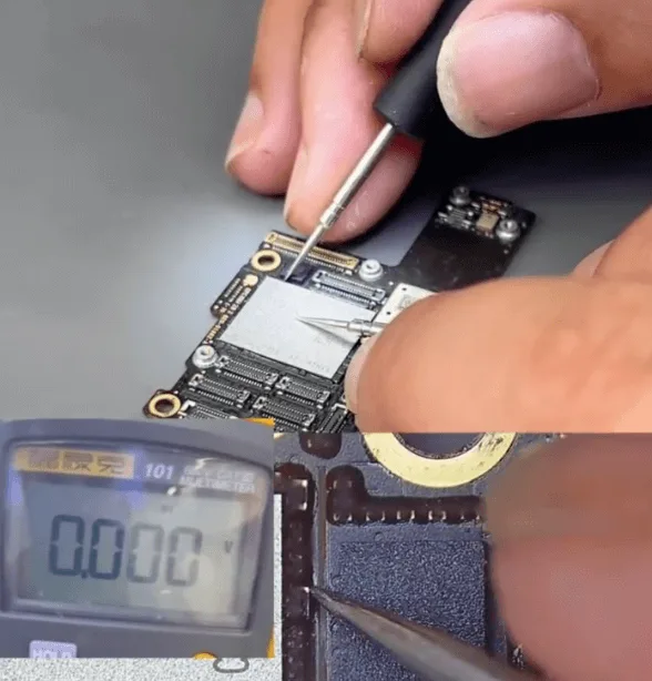
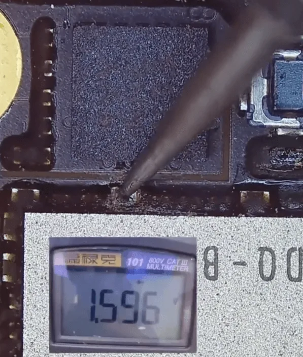
    • Use a multimeter to check the power supply rails associated with the NAND chip and CPU.
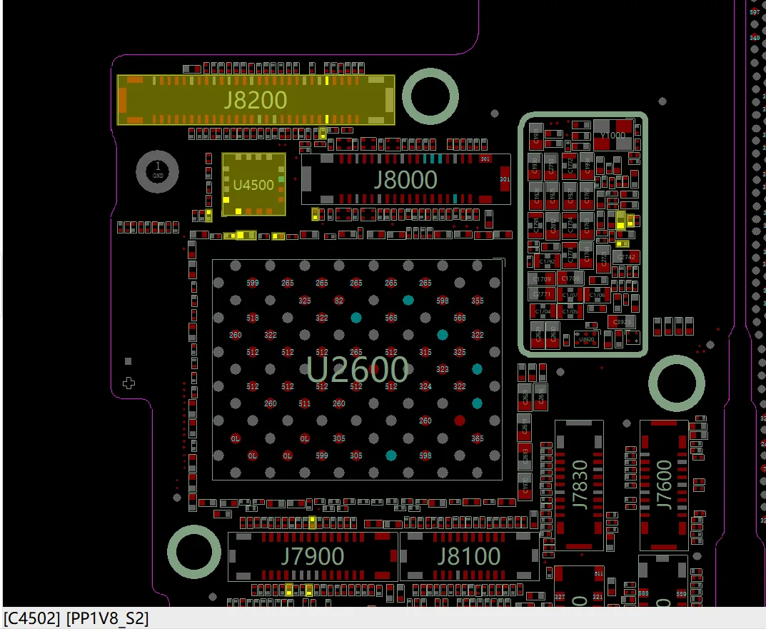
    • After carefully checking the small capacitors around the NAND chip, one rail shows a short circuit. The affected rail is the 1.8V power supply rail (PP1V8_S2) for the NAND.

    Processus de réparation

    1: Removing the Shorted Capacitor
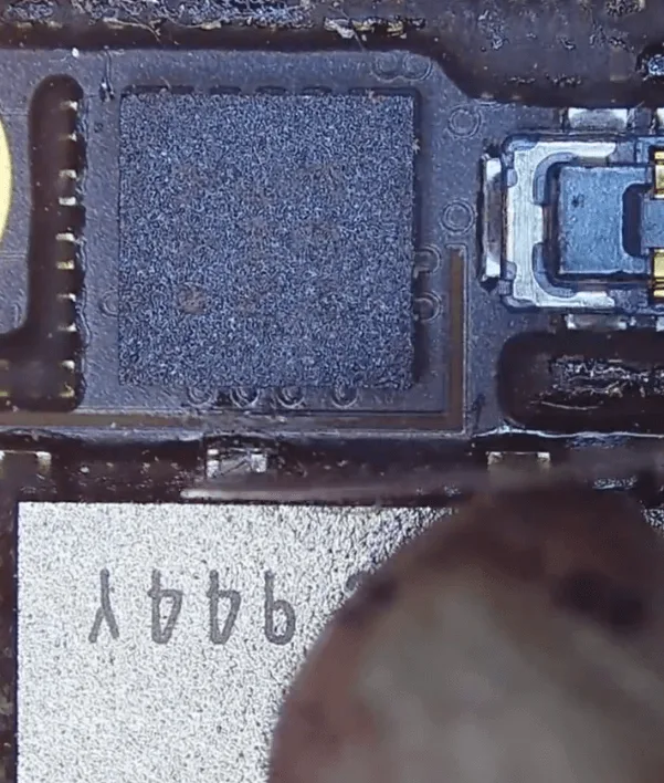
    • Carefully remove the black glue covering the NAND chip using a hot air gun and a blade knife.
    • Identify and remove the shorted capacitor, which is a filter-type capacitor. Since it’s a filter capacitor, it can be safely removed without replacement.

    Recheck the diode value on the rail after removing the capacitor, and confirm that it has returned to normal.

    2: Reassembling the Motherboard
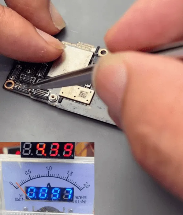
    • Connect the motherboard to the DC power supply and trigger the boot process again. This time, the boot current returns to normal.
    • Recombine the two layers of the motherboard using a hot air gun, ensuring a proper fit.

    3: Final Assembly and Testing
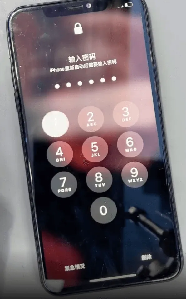
    iphone 11 pro max black screen no boot issue repair phone can be booted
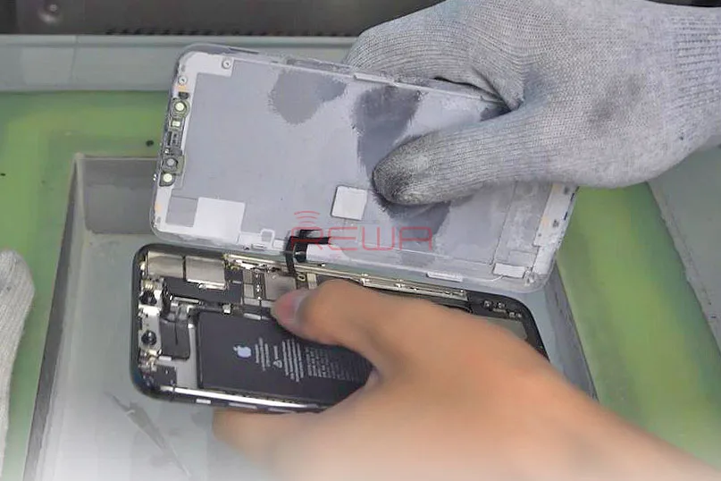
    • Reassemble the motherboard with the housing and other parts, taking care to install the waterproof seal sticker.
    • Assemble the screen and press the power button to conduct a final test.
    • After testing, all functions of the phone are working correctly. The no-boot issue has been successfully resolved by removing the shorted filter-type capacitor.

    Conclusion :

    Repairing an iPhone 11 Pro Max that won’t boot due to a black screen can be a challenging task, but by following a systematic approach, the issue can be identified and resolved. In this case, removing a shorted capacitor from the NAND power supply rail restored the device to full functionality. For those facing similar issues, this guide provides a clear path to bring your device back to life. Stay tuned for more detailed repair guides to help you tackle even the most complex smartphone issues.
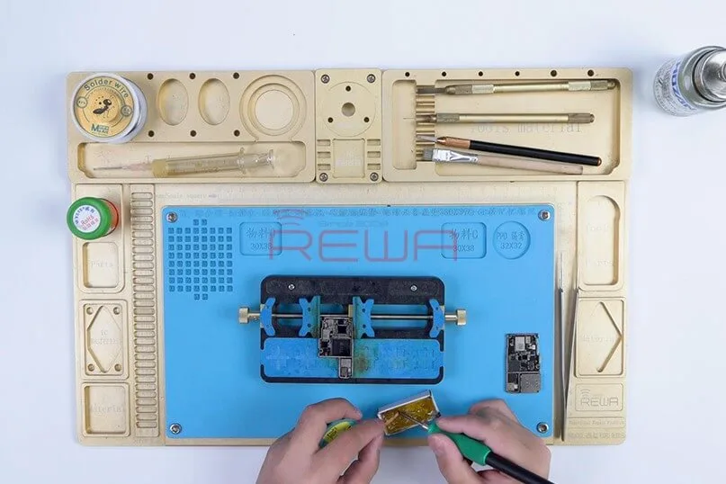
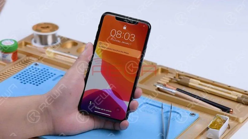
  • Dépannage de l'iPhone 11 Pro Max sans service

    Dépannage de l'iPhone 11 Pro Max sans service

    Récemment, de nombreux techniciens de réparation ont signalé qu'ils avaient reçu un grand nombre d'iPhone 11 Pro Max sans service.

    Pire encore, le défaut n'a pas pu être éliminé après le remplacement de la carte de signalisation.

    Sur la base de leur expérience, les techniciens REWA LAB concluent à titre préliminaire que le défaut se situe probablement au niveau des pads de signal de la carte logique. Vérifions-le !

    Étape 1 : Analyse des défaillances

    La carte mère a été réparée une fois.

    La panne initiale n'était pas due au service, mais au micrologiciel du modem de bande de base.

    La réparation précédente a soudé l'unité centrale de bande de base et l'EPROM de bande de base à une carte de signal en bon état.

    Mais le téléphone ne fonctionnait toujours pas. On peut estimer, à titre préliminaire, qu'il y a deux possibilités de panne.

    L'une d'entre elles est la détérioration de l'unité centrale de bande de base et de l'EPROM de bande de base.

    L'autre est la détérioration des circuits liés au signal sur la carte logique.

    Tout d'abord, nous installons la carte mère sur le téléphone à tester.

    Le téléphone s'allume normalement mais ne fonctionne pas.
    Tout d'abord, nous installons la carte mère sur le téléphone pour le tester. Le téléphone s'allume normalement mais n'a pas de service.

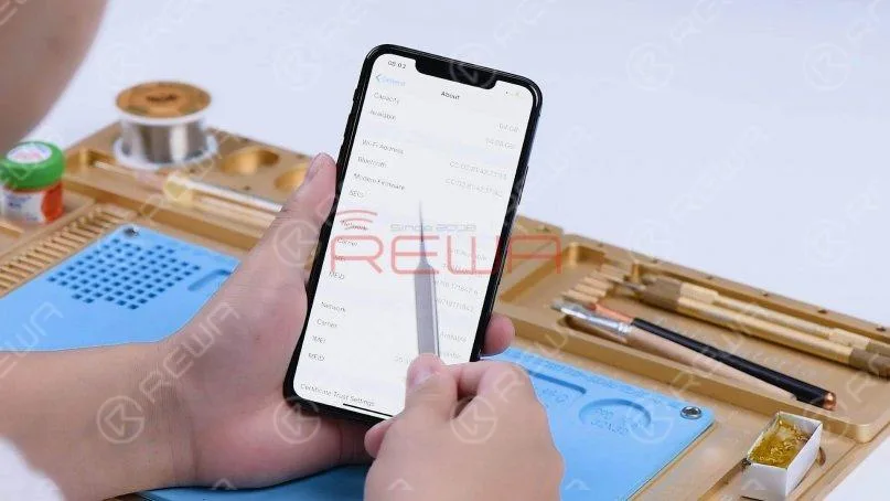
    Allez dans Paramètres, Général et À propos. Nous pouvons voir que le téléphone n'a pas de micrologiciel de modem.
    Allez dans Paramètres, Général et À propos. Nous pouvons voir que le téléphone n'a pas de micrologiciel de modem.

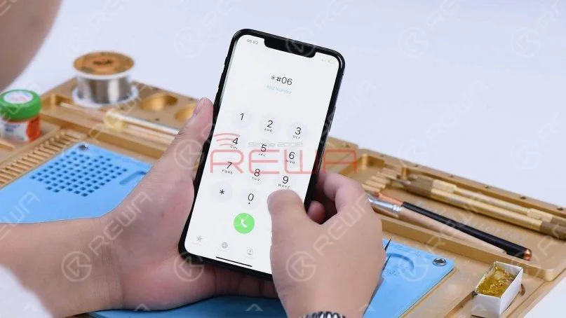
    Composez *#06# et l'IMEI n'est pas visible.

    Composez *#06# et l'IMEI n'est pas visible.

    Le téléphone était équipé d'un micrologiciel de modem, mais il ne l'est plus. La cause peut être liée à une pseudo soudure de la couche centrale de la carte mère ou à un endommagement de l'unité centrale de bande de base et de l'EPROM de bande de base.

    Étape 2 : Séparation de la carte mère et dépannage

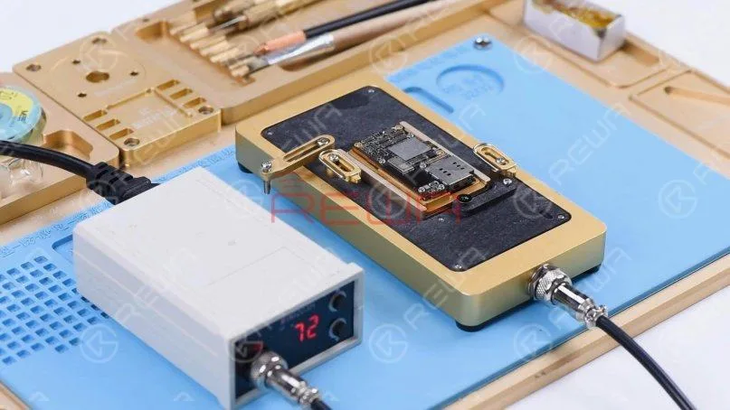
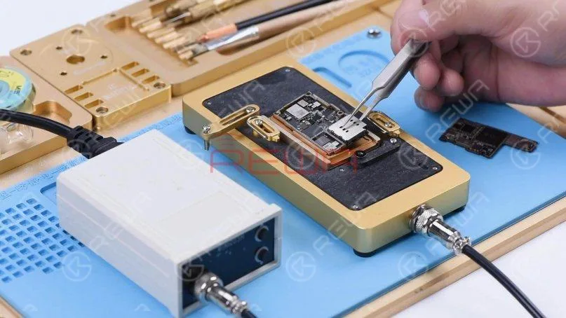
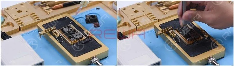
    Ensuite, nous séparons la carte mère pour localiser le composant défectueux. Placez la carte mère sur le Plate-forme de chauffage et régler la température sur 185℃.

    Ensuite, nous séparons la carte mère pour localiser le composant défectueux. Placer la carte mère sur la plateforme chauffante et régler la température à 185℃.

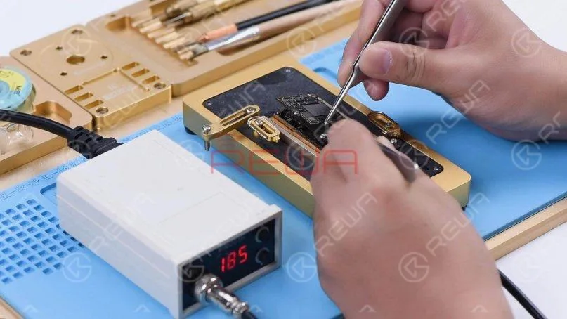
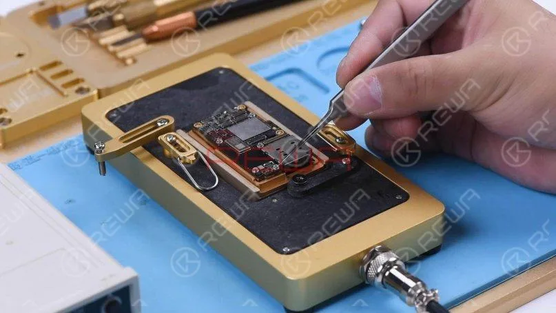
    Lorsque la température est montée à 185℃, retirer la carte logique avec une pince à épiler.
    Lorsque la température est montée à 185℃, retirer la carte logique avec une pince à épiler.

    Mettez l'appareil hors tension et retirez le tableau de signalisation.

    Mettez l'appareil hors tension et retirez le tableau de signalisation.

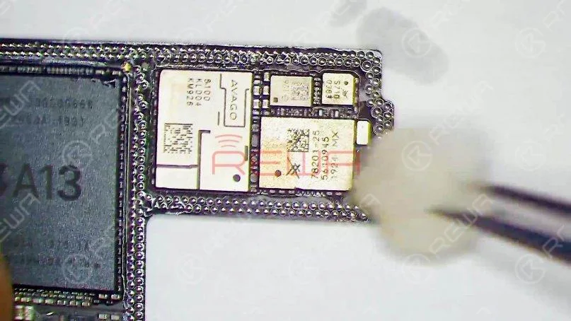
    Nettoyez la carte logique avec du PCB Cleaner.

    Puisque la carte de signalisation a été remplacée, nous devons d'abord vérifier la carte logique.

    En fonction du résultat du test, nous pouvons déterminer ultérieurement si l'unité centrale de bande de base et l'EPROM sont endommagées.

    Nettoyez la carte logique avec du PCB Cleaner. Puisque la carte de signal a été remplacée, nous devons d'abord vérifier la carte logique. En fonction du résultat du test, nous pourrons déterminer ultérieurement si l'unité centrale de bande de base et l'EPROM sont endommagées.

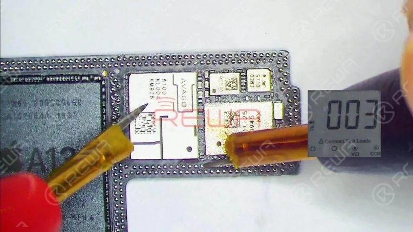
    Effectuez des mesures en mode diode sur les pastilles de signal de la couche centrale de la carte logique.

    Lors de la mesure de la broche 131, la valeur de la diode est de 003. La valeur normale devrait être d'environ 400.

    Effectuez une mesure en mode diode des plots de signal sur la couche centrale de la carte logique. Lors de la mesure de la broche 131, la valeur de la diode est de 003. La valeur normale devrait être d'environ 400.

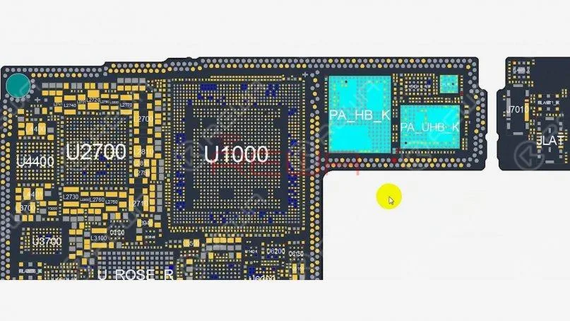
    Ouvrez l'image et de nombreux composants associés apparaissent sur le circuit.

    Ouvrez l'image et de nombreux composants associés apparaissent sur le circuit.

    Nous localisons ensuite le composant défectueux à l'aide d'un détecteur de colophane.

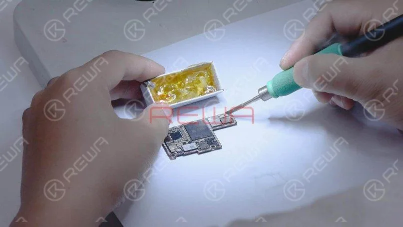
    Tremper la colophane avec le fer à souder à 365℃ et fumer un peu de colophane sur les composants associés.
    Nous localisons ensuite le composant défectueux à l'aide d'une détection à la colophane. Tremper de la colophane avec un fer à souder à 365℃ et fumer de la colophane sur les composants associés.

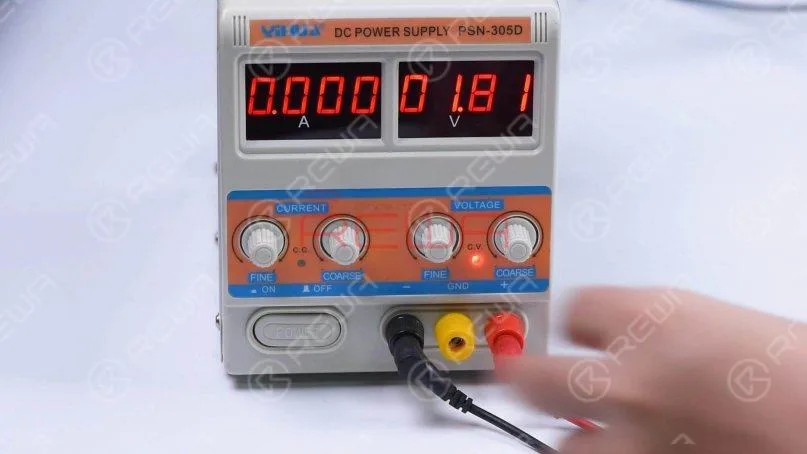
    Régler l'alimentation en courant continu à 1,8 V. Relier l'anode positive et l'anode négative de l'alimentation en courant continu avec des sondes de multimètre.
    Régler l'alimentation en courant continu à 1,8 V. Relier l'anode positive et l'anode négative de l'alimentation en courant continu avec des sondes de multimètre.

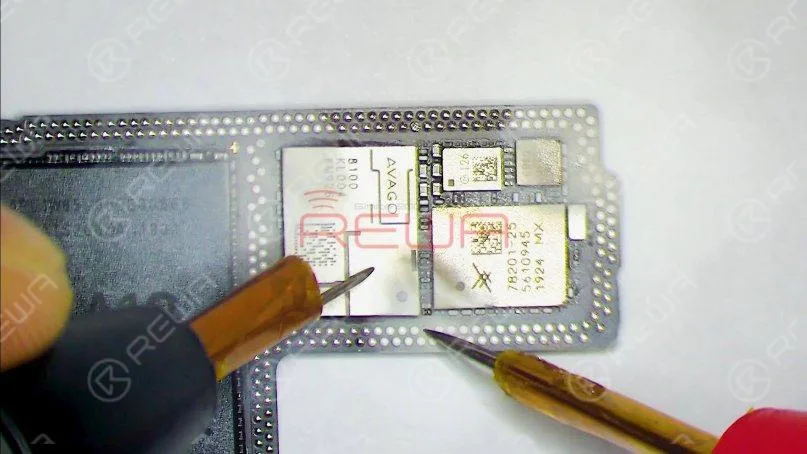
    Connectez ensuite la sonde noire à la terre et la sonde rouge à la broche 113 de la carte logique. On peut voir que la colophane d'un condensateur a fondu.

    Il indique que le composant est endommagé. Ce circuit comporte plusieurs condensateurs de filtrage, ce qui nous permet de retirer directement le condensateur endommagé.
    Connectez ensuite la sonde noire à la terre et la sonde rouge à la broche 113 de la carte logique. Nous pouvons voir que la colophane d'un condensateur a fondu. Cela indique que le composant est endommagé. Ce circuit comporte plusieurs condensateurs de filtrage, ce qui nous permet de retirer directement le condensateur endommagé.

    Retirer le condensateur avec Pistolet à air chaud à 350℃ et flux d'air 3.

    Retirer le condensateur avec un pistolet à air chaud à 350℃ et un flux d'air 3.

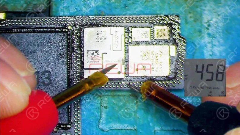
    Mesurez à nouveau la carte logique après qu'elle ait refroidi. La valeur de la diode revient à une valeur normale de 458.
    Mesurez à nouveau la carte logique après qu'elle ait refroidi. La valeur de la diode revient à une valeur normale de 458.

    Étape 3 : Restauration de la carte mère

    Ensuite, nous devons restaurer la carte mère.

    Tout d'abord, nous devons enlever l'étain sur le plot de collage de la carte mère.

    Enduire la colophane avec le fer à souder à 365℃ et la mèche à souder pour enlever l'étain sur le tampon de liaison.

    Ensuite, nous devons restaurer la carte mère. Tout d'abord, nous avons besoin d'enlever l'étain sur le bonding pad de la carte mère. Enduire la colophane avec le fer à souder à 365℃ et la mèche à souder pour enlever l'étain sur le pavé de liaison.

    Enlever l'étain sur le tableau de signalisation avec la même méthode.

    Ensuite, nettoyez la carte logique et la carte de signal avec du PCB Cleaner.

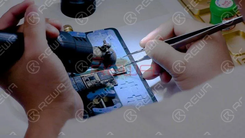
    Ensuite, fixez le tableau de signalisation à la plate-forme de reballage et mettez le pochoir de reballage en place.

    Appliquer uniformément une couche de pâte à braser à température moyenne.
    Enlevez l'étain sur la carte de signal avec la même méthode. Nettoyez ensuite la carte logique et la carte de signal avec le nettoyant pour PCB. Ensuite, fixez la carte de signal à la plate-forme de rebouclage et mettez le pochoir de rebouclage en place. Appliquez uniformément une couche de pâte à souder à température moyenne.

    Après le reballage, placer le panneau de signalisation sur la plate-forme chauffante de 185℃ pour le chauffer.

    Lorsque les billes de soudure sont formées, éteignez l'appareil et laissez refroidir la carte de signal.
    Après avoir refait les billes, placez la carte de signal sur la plateforme chauffante de 185℃ pour chauffer. Lorsque les billes de soudure sont formées, coupez l'alimentation et refroidissez la carte de signal.

    Appliquer quelques Flux en pâte au plot de connexion de la carte de signalisation et aligner la carte logique sur la carte de signalisation.
    Appliquer un peu de pâte de flux sur le plot de liaison de la carte de signal et aligner la carte logique sur la carte de signal.

    Continuez à chauffer la carte mère sur la plateforme chauffante de 185℃.

    Pousser doucement la carte logique avec une pince à épiler et la carte logique peut revenir à sa position précédente.

    Il indique que la soudure de la carte mère est terminée.

    Continuez à chauffer la carte mère sur la plateforme chauffante de 185℃. Poussez la carte logique doucement avec des pincettes et la carte logique peut revenir à la position précédente. Cela montre que la carte mère a terminé la soudure.

    Éteignez l'appareil et laissez refroidir la carte mère pendant 5 minutes.

    Retirez ensuite la carte mère et installez-la sur le téléphone.

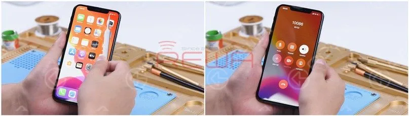
    Le téléphone s'allume normalement et le signal 4G peut être reçu.

    Il est également possible d'effectuer un appel téléphonique. Le défaut est supprimé.

    Éteignez l'appareil et laissez refroidir la carte mère pendant 5 minutes. Retirez ensuite la carte mère et installez-la sur le téléphone. Le téléphone s'allume normalement et le signal 4G peut être reçu. Il est également possible de passer un appel téléphonique. Le problème est résolu.

    Résumé

    L'iPhone 11 Pro Max a été réparé une fois et ne fonctionne toujours pas après que le processeur de bande de base et l'EPROM aient été soudés à une bonne carte de signal.

    On peut d'emblée estimer qu'il y a deux possibilités de défaillance. L'une est la détérioration de l'unité centrale de bande de base et de l'EPROM de bande de base. L'autre est la détérioration des circuits liés au signal sur la carte logique.

    En mesurant les plots de signal sur la carte logique et en détectant la colophane, un condensateur a été trouvé endommagé.

    Après avoir retiré le condensateur, le défaut de service a été supprimé.

    Nous pouvons exclure la possibilité d'un défaut de l'unité centrale de bande de base et de l'EPROM puisque le défaut de fonctionnement a été éliminé après la réparation de la carte logique.

    Si vous souhaitez en savoir plus, n'hésitez pas à visiter notre site web. académie pour les cours de réparation.

  • iPhone 11 Pro Max Screen Refurbishing – Detailed Operation

    iPhone 11 Pro Max Screen Refurbishing – Detailed Operation

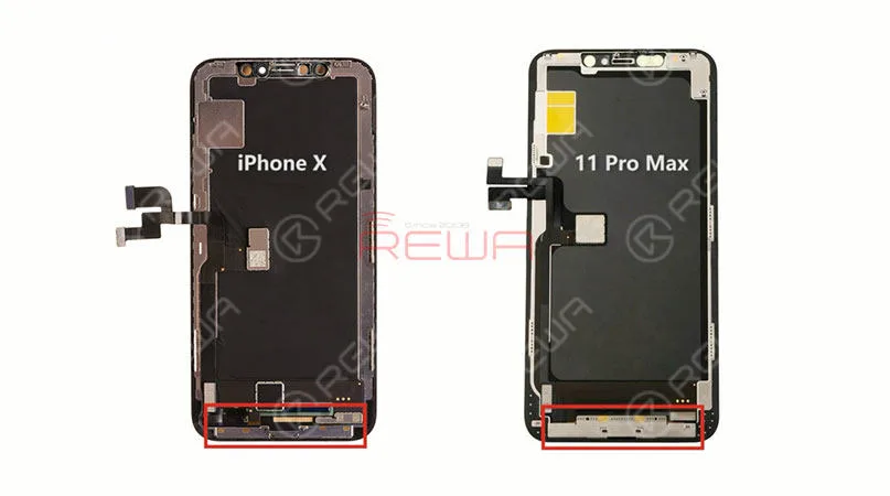
    For iPhone X and later iPhone models, the bracket covering the bottom flex cable bonding area is adhered by cold adhesive. The traditional method with heating assistance when removing bezel might damage the screen. After several attempts, REWA LAB found that the new method with cold assistance can improve the success rate and efficiency of screen refurbishing. Check our blog today for detailed operation process of iPhone 11 Pro Max screen refurbishing.
    For iPhone X and later iPhone models, the bracket covering the bottom flex cable bonding area is adhered by cold adhesive. The traditional method with heating assistance when removing bezel might damage the screen. After several attempts, REWA LAB found that the new method with cold assistance can improve the success rate and efficiency of screen refurbishing. Check our blog today for detailed operation process of iPhone 11 Pro Max screen refurbishing.

    The screen structure of iPhone 11 Pro Max is the same as that of iPhone X series. Therefore, the screen refurbishing process is also similar. Different from iPhone X series, the bracket covering the bottom flex cable bonding area of iPhone 11 Pro Max is relatively wide, which increases the difficulty of screen refurbishing. Therefore, we need to be extremely careful when removing the bezel.

    Reconditionnement d'écran iPhone 11 Pro Max

    Step 1 Screen Testing

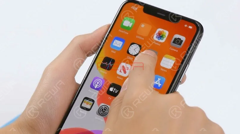
    The first thing we do is to test the screen. Test the display, touch functionality and Haptic Touch of the screen. All going well.
    The first thing we do is to test the screen. Test the display, touch functionality and Haptic Touch of the screen. All going well.

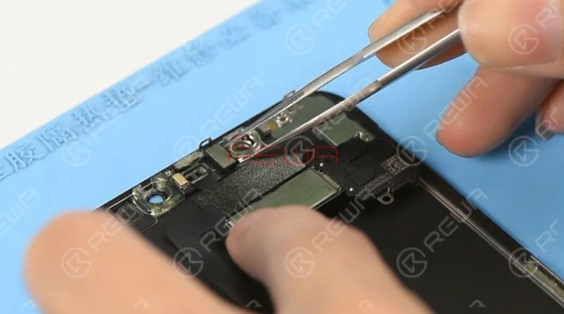
    Please be noted that when testing iPhone 11 Pro Max’s screen, the default brightness of the screen is set at the lowest level. To adjust brightness of the screen during the testing, we need to get the front panel sensor assembly flex cable connected. Disconnect the front panel sensor assembly flex cable and remove the OLED screen assembly. Then remove the front panel sensor assembly flex cable.
    Please be noted that when testing iPhone 11 Pro Max’s screen, the default brightness of the screen is set at the lowest level. To adjust brightness of the screen during the testing, we need to get the front panel sensor assembly flex cable connected. Disconnect the front panel sensor assembly flex cable and remove the OLED screen assembly. Then remove the front panel sensor assembly flex cable.

    Tips: it is not easy to remove the front panel sensor assembly flex cable, which can be easily damaged during the operation. And the damage can also affect the function of Face ID. So we need to be extremely careful when operating

    Step 2 Bezel Removing

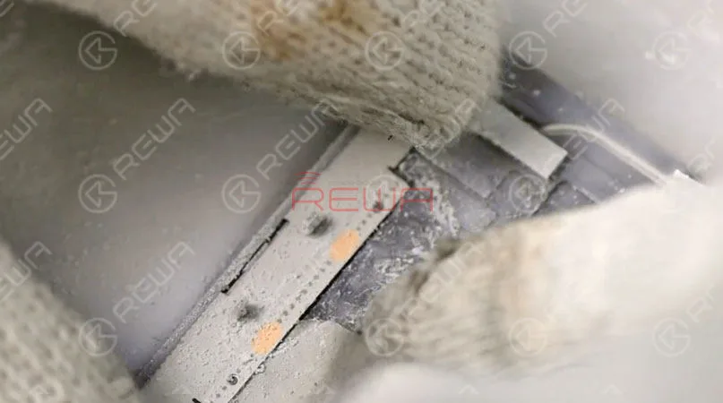
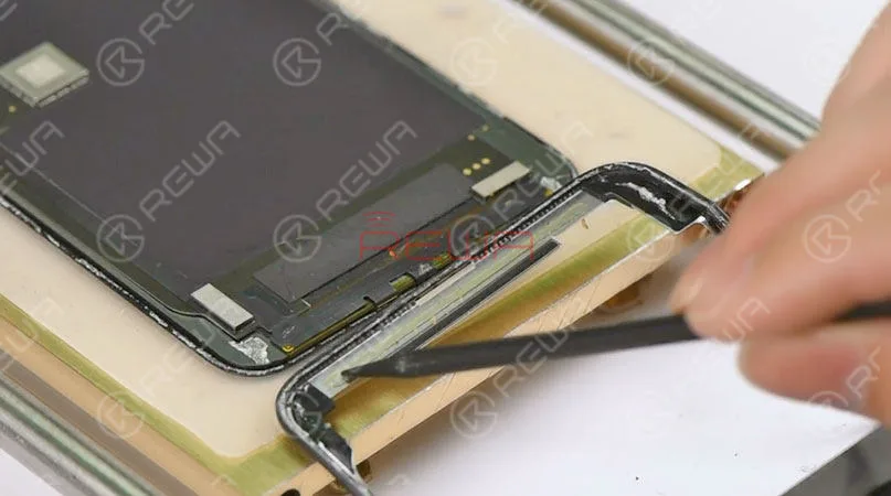
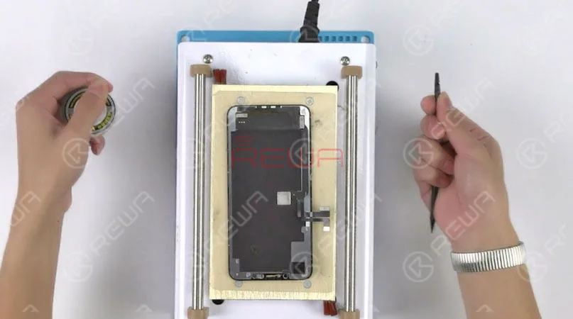
    Place the OLED screen assembly upside down into the -180℃ Frozen LCD Screen Separator. Insert a 0.06mm metal pry piece under the bracket covering the bottom flex cable bonding area. Slide back and forth to slice through the cold adhesive here. Once done, connect the screen and test. All going well.
    Place the OLED screen assembly upside down into the -180℃ Frozen LCD Screen Separator. Insert a 0.06mm metal pry piece under the bracket covering the bottom flex cable bonding area. Slide back and forth to slice through the cold adhesive here. Once done, connect the screen and test. All going well.

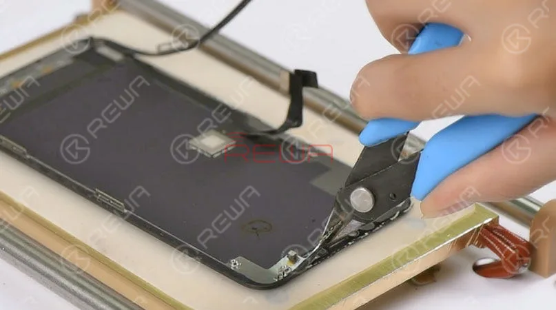
    Tips: since the front panel sensor assembly flex cable is not connected, the default brightness of the screen is set at the lowest level. Set temperature of the Heat Platform at 100℃. Then put the OLED Screen Assembly on the preheated platform. Press the ‘Start’ button to suck the screen. 1 minute later, remove the front camera and sensor holder. Cut out the top bracket with the Cutting Nipper. Then separate the bezel from the OLED with the Cutting Nipper.
    Tips: since the front panel sensor assembly flex cable is not connected, the default brightness of the screen is set at the lowest level. Set temperature of the Heat Platform at 100℃. Then put the OLED Screen Assembly on the preheated platform. Press the ‘Start’ button to suck the screen. 1 minute later, remove the front camera and sensor holder. Cut out the top bracket with the Cutting Nipper. Then separate the bezel from the OLED with the Cutting Nipper.

    Tips: when detaching the bezel at the bottom area of the phone, we need to insert the metal pry piece under the bracket covering the bottom flex cable bonding area and slide back and forth. This is to confirm that the cold adhesive here has been sliced open. The bezel has been removed completely. As you can see, the area here is adhered by cold adhesive in large amounts. To protect the OLED from damage, we’d better freeze the screen during the operation.
    Tips: when detaching the bezel at the bottom area of the phone, we need to insert the metal pry piece under the bracket covering the bottom flex cable bonding area and slide back and forth. This is to confirm that the cold adhesive here has been sliced open. The bezel has been removed completely. As you can see, the area here is adhered by cold adhesive in large amounts. To protect the OLED from damage, we'd better freeze the screen during the operation.

    Again, let’s test the OLED Screen Assembly. All going well.

    Step 3 Glass Lens Separating

    Now, let’s move to the glass lens separating process.

    Step 3 Glass Lens Separating   Now, let’s move to the glass lens separating process.

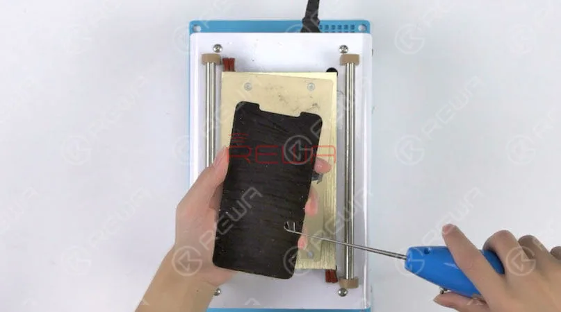
    Place the OLED Screen Assembly upside down on the Heat Platform. Remove residual glue on the earpiece speaker area with a blade. So that the Touch Panel will not be damaged when operating with the Cutting Wire. Next, separate the glass lens from OLED with Cutting Wire. Test again after separating. All going well.

    Step 4 OCA Glue Removing

    Let’s continue with OCA glue removing.

    Put the OLED screen upside down on the Heat Platform for 3 minutes. Make an incision with the Electric Glue Removing Device. Then continue to tear off the OCA Glue with one hand. Also, be careful with force applied. This is to avoid damaging the OLED screen. Once done, test the OLED Screen. All going well.

    Put the OLED screen upside down on the Heat Platform for 3 minutes. Make an incision with the Electric Glue Removing Device. Then continue to tear off the OCA Glue with one hand. Also, be careful with force applied. This is to avoid damaging the OLED screen. Once done, test the OLED Screen. All going well.

    Step 5 Laminating

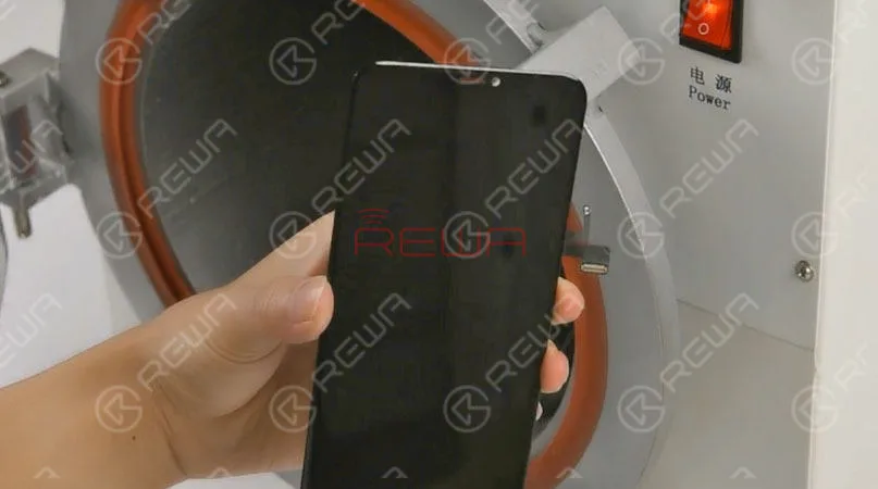
    Tear off the protective film on the backside of the glass lens and attach the OCA to the right position of the glass lens. Then put the OCA attached glass lens into the bubble removing machine for 5 minutes. Once finished, take out the OCA attached glass lens.
    Tear off the protective film on the backside of the glass lens and attach the OCA to the right position of the glass lens. Then put the OCA attached glass lens into the bubble removing machine for 5 minutes. Once finished, take out the OCA attached glass lens.

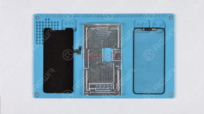
    Now we need to laminate the OCA attached glass lens to the OLED Screen. Place the OLED screen into the OLED aligning mold. Clean the screen with the lint-free wiper. Tear off another layer of the OCA protective film and attach the OCA attached glass lens to the right position of the screen. Press gently to fit the glass lens with the screen. Place the mold upside down and take out the OLED Screen Assembly. Tear off the protective film on the glass lens. Cover the backside of the OLED Screen Assembly with a laminating sponge and then place the OLED Screen Assembly into the laminating machine. Choose ‘start’ on the LED panel. The machine starts to work. Laminating finished after several minutes. Again, let’s test the OLED Screen Assembly. All going well.

    Step 6 Bubble Removing

    Put the OLED Screen Assembly into Bubble Removing Machine for 10 minutes. Once finished, take out the OLED Screen Assembly.

    Put the OLED Screen Assembly into Bubble Removing Machine for 10 minutes. Once finished, take out the OLED Screen Assembly.

    Step 7 Bezel Attaching

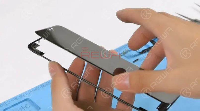
    Prepare a new piece of iPhone 11 Pro Max bezel. Tear off the protective film on the bezel. Apply the specialized glue to the bezel. Then apply pressure to fit the OLED Screen Assembly with the bezel.

    Prepare a new piece of iPhone 11 Pro Max bezel. Tear off the protective film on the bezel. Apply the specialized glue to the bezel. Then apply pressure to fit the OLED Screen Assembly with the bezel.

    Please be noted the FPC area on the bottom is very fragile. Be careful when operating. Otherwise, you might damage the OLED screen.
    Please be noted the FPC area on the bottom is very fragile. Be careful when operating. Otherwise, you might damage the OLED screen.

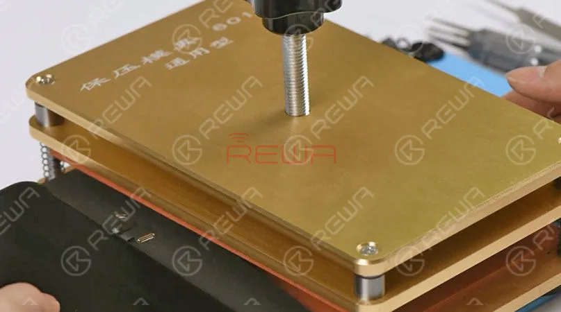
    Cover the backside of the OLED Screen Assembly with a laminating sponge. Then place the OLED Screen Assembly into the bezel laminating mold and fix it. Tighten the screw and wait for 10 minutes. Take out the OLED Screen Assembly afterwards.

    Step 8 Screen Testing

    Get the front camera and sensor holder installed, and then the earpiece speaker mesh. Get the front panel sensor assembly flex cable and the OLED Screen Assembly installed. Run function test – Display; Touch; Haptic Touch. Display, Touch, and Haptic Touch work normally.
    Get the front camera and sensor holder installed, and then the earpiece speaker mesh. Get the front panel sensor assembly flex cable and the OLED Screen Assembly installed. Run function test - Display; Touch; Haptic Touch. Display, Touch, and Haptic Touch work normally.

    iPhone 11 Pro Max screen refurbishing has been completed perfectly.

    Outils et pièces détachées utilisés

    Vous pouvez également visiter Chaîne Youtube de REWA  to check our video of iPhone 11 pro max refurbishing.

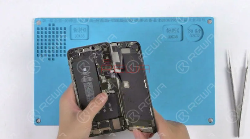
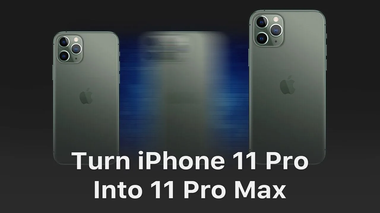
  • Transformer l'iPhone 11 Pro en iPhone 11 Pro Max

    Transformer l'iPhone 11 Pro en iPhone 11 Pro Max

    Can iPhone 11 Pro possibly be turned into iPhone 11 Pro Max? It is actually theoretically possible. With pins of the two phones’ display connector and touch connector functioning almost the same, we can turn an iPhone 11 Pro into an iPhone 11 Pro Max by changing board ID resistors. Check our video now and find out how we finally made it.

    Warm Tips: This video is made for technique sharing only. For those who have no professional skills, please look before you leap.

    Tools & Parts used to separate iPhone 11 Pro: