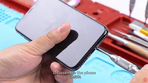
iPhone won’t turn on and the screen is black or frozen? After software issue being excluded, the problem may be caused by a faulty logic board. Since logic board of iPhone X is a single one that’s basically been folded over and soldered together, the unique design and structure have made any repairs to the logic board far more difficult than previous series. With our iPhone X won’t power on repair case today, the fault has been confirmed as inductor damage by voltage measurement. And we can fix the iPhone X won’t turn on issue by inductor replacing and board re-soldering. Let’s check out the video to see how to fix iPhone X black screen issue.
Etiqueta: iphone
-
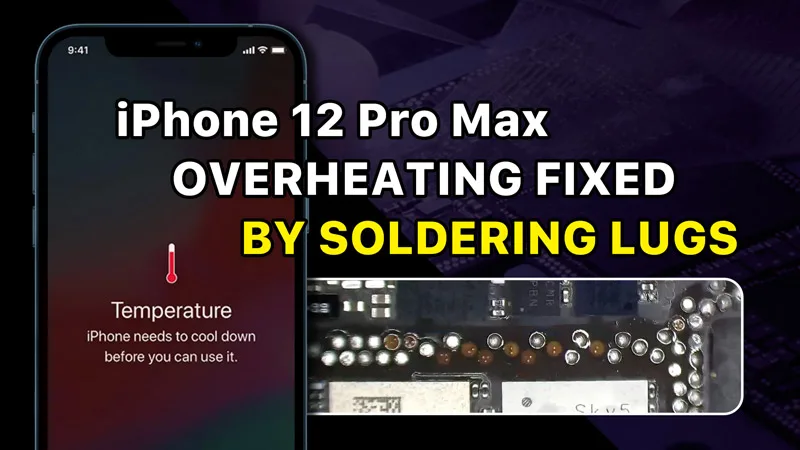
Cómo solucionar el problema de sobrecalentamiento del iPhone 12 Pro Max con tapones de soldadura
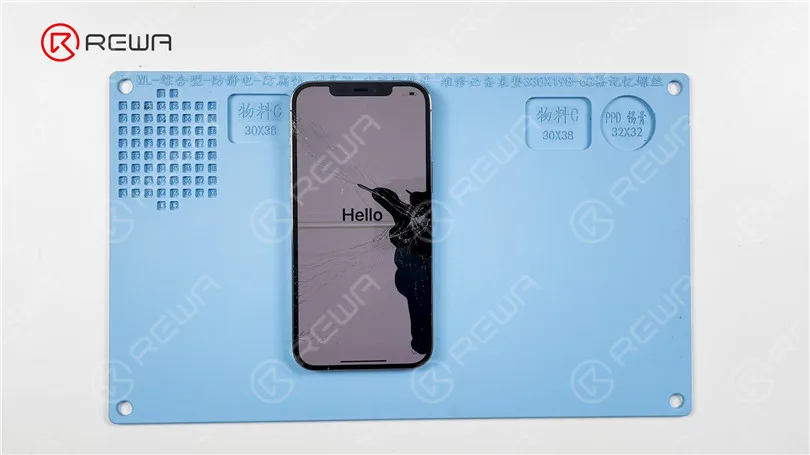
Hoy compartiremos cómo solucionar el problema de sobrecalentamiento o advertencia de temperatura del iPhone 12 Pro Max. El teléfono se ha caído antes y la pantalla está agrietada. Después del arranque, el teléfono muestra una advertencia de temperatura.
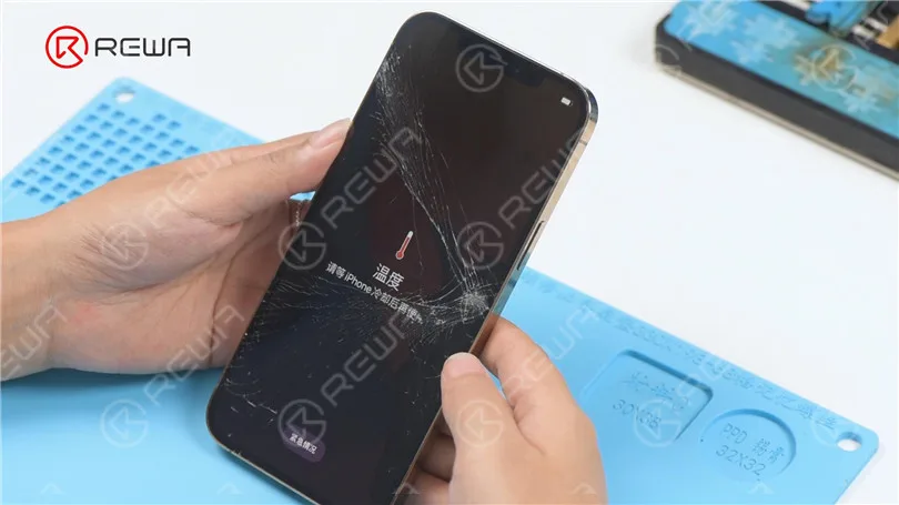
A continuación, desmontamos el teléfono para probarlo. Desconecte los cables flexibles. Retiramos la placa base. En primer lugar, comprobamos si la placa base está deformada. La placa base no está deformada.
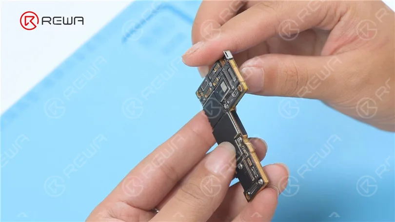
Se puede ver al microscopio que la placa base tiene pseudo-soldadura. Entonces tenemos que separar la placa base.
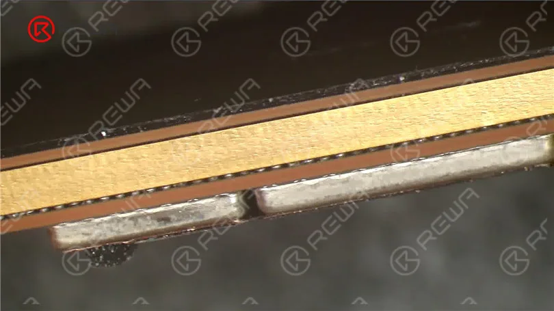
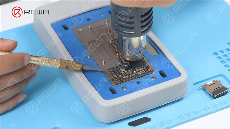
Separe la espuma y la parte de plástico. Coloque la placa base en el 165 °C Plataforma de calefacción para calentar. Dado que la capa media de la línea iPhone 12 adopta pasta de soldadura de temperatura media para soldar, tenemos que ayudar al calentamiento con una pistola de aire caliente a 330 °C. Intente levantar la placa lógica con una palanca mientras se calienta. Si la placa lógica se suelta, retírela. A continuación, retire la placa de señal.
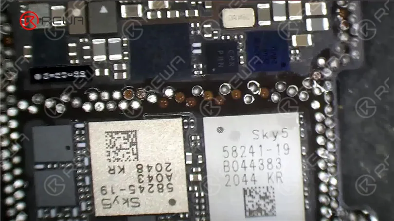
Al microscopio se ve que faltan almohadillas en la placa lógica. Entonces hay que reparar las almohadillas de unión. Limpie las almohadillas de unión con Soldador a 380 °C y Solder Wick. A continuación, limpie las almohadillas de unión con PCB Cleaner.
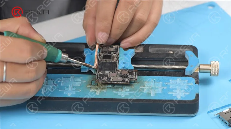
A continuación, raspe las almohadillas que faltan para mostrar los circuitos con un cuchillo de esculpir. Presta atención a no dañar la GND mientras raspas.
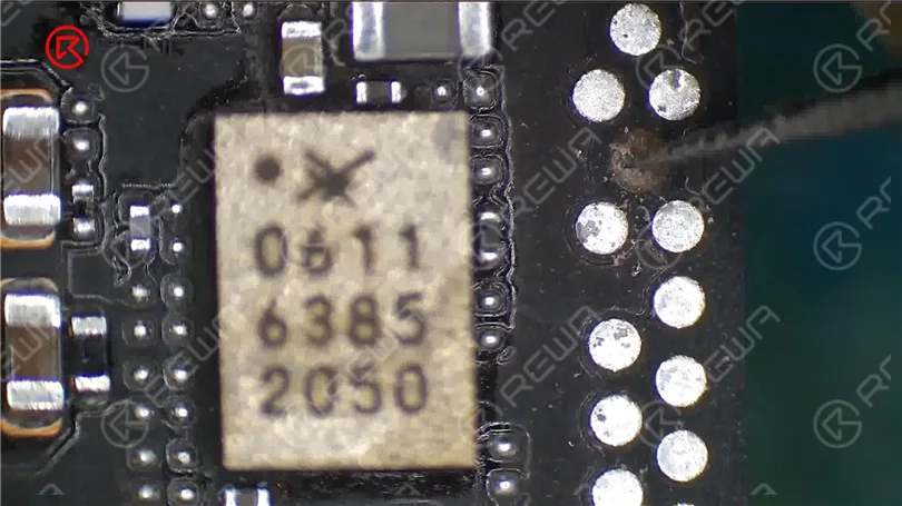
Limpie las pastillas de conexión con PCB Cleaner. Aplique estaño a las almohadillas de unión con un soldador.
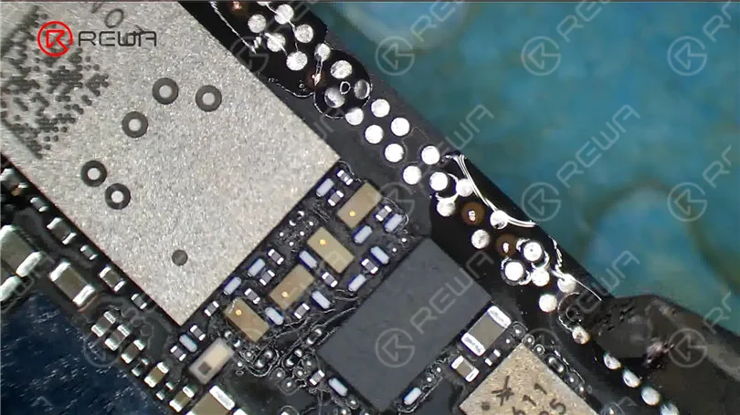
A continuación, ponemos el Clavijas de soldadura en posición. Aplique un poco de fundente en pasta. Calentar con un soldador para soldar. Limpie las almohadillas de unión con PCB Cleaner.
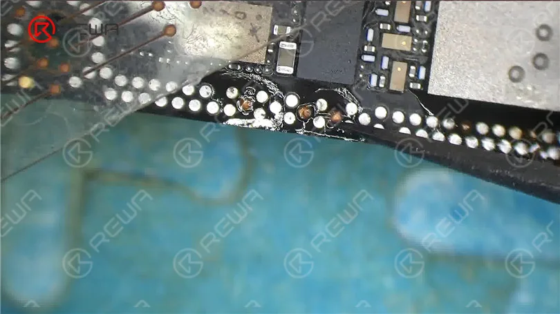
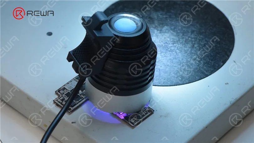
Aplique un poco de máscara de soldadura a las almohadillas de unión. A continuación, solidificar con una Lámpara UV. Después de solidificar, retire el exceso de máscara de soldadura con un cuchillo de escultura para mostrar las almohadillas.
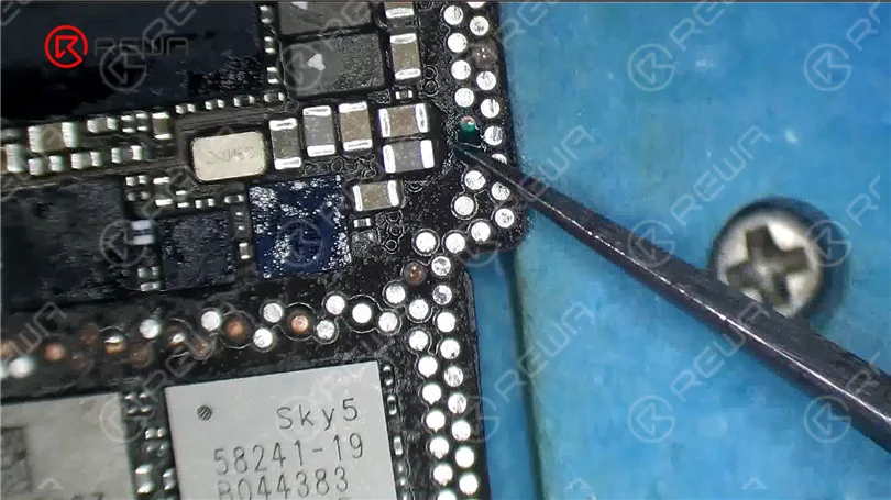
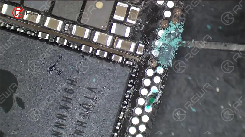
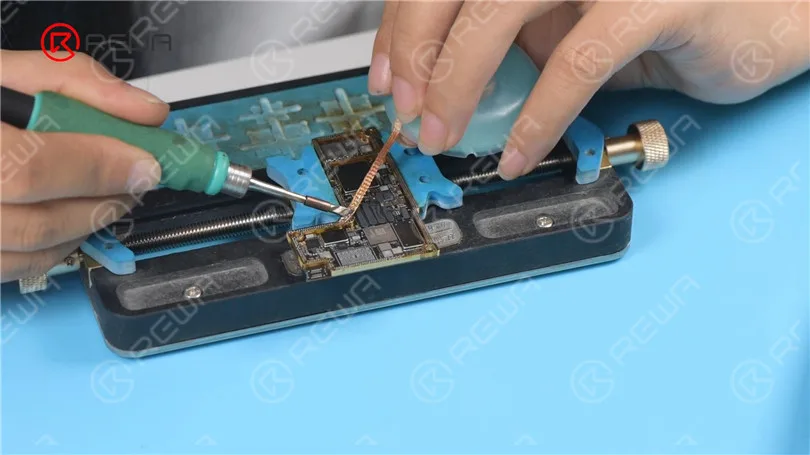
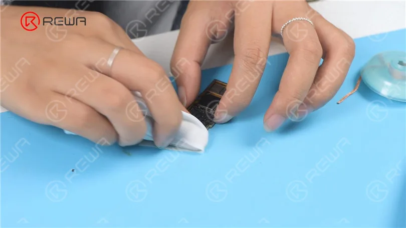
Limpie las almohadillas de unión con PCB Cleaner. A continuación, limpie las almohadillas de unión con el soldador y la mecha de soldadura. Siga limpiando las almohadillas de unión con un paño sin polvo.
A continuación, volvemos a colocar la placa de señales. Coloca la placa de señales en el soporte. Coloca la plantilla de reballing en posición. Aplica un poco de Pasta de Soldadura de baja temperatura uniformemente. Retire el exceso de pasta de soldadura.
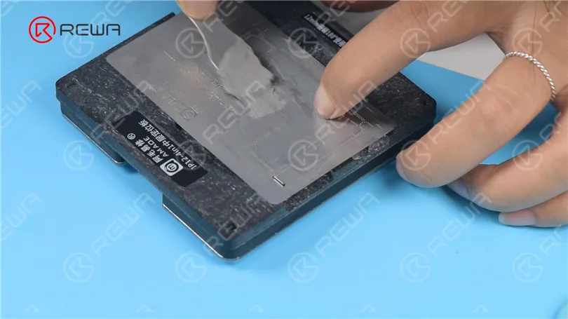
Separe la plantilla de recombinación. Coloque la placa base en la plataforma de calentamiento a 165 °C para calentarla para la recombinación. Retire la placa base después de que se haya enfriado durante 5 minutos.
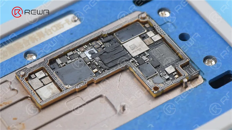
Instale la placa base para realizar pruebas. Conecte la pantalla. El teléfono se enciende con normalidad. El aviso de temperatura ha desaparecido.
-
El iPhone 11 Pro no se enciende - Guía de reparación profesional
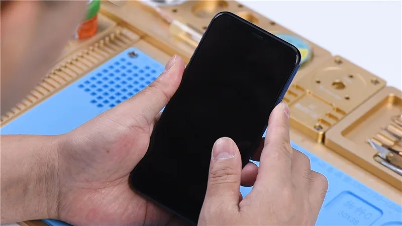
¡¡¡Hola a todos!!! Nuestro curso de hoy trata sobre cómo reparar un iPhone 11 Pro que no enciende.
Pulsa el botón de encendido. El teléfono no se enciende.
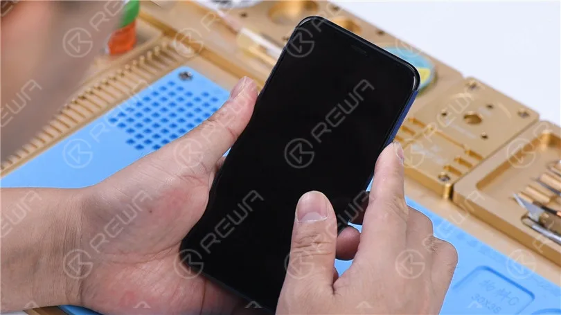
Desmontar y probar
Luego desmontamos el teléfono y lo probamos.
Retire los dos tornillos pentalobulados del borde inferior.
Tire hacia arriba de la pequeña protuberancia de la ventosa para levantar la pantalla.
Inserte una pieza de apriete cuando haya un hueco y deslícela a lo largo del hueco.
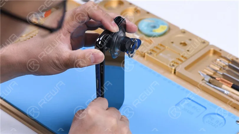
Una vez levantada la pantalla, retire las cubiertas de blindaje.
Desconecte la batería y retire la pantalla. Conecte la placa base con el cable de alimentación.
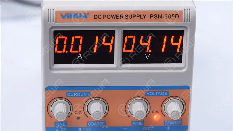
El amperímetro muestra una gran corriente de 3,1 A.
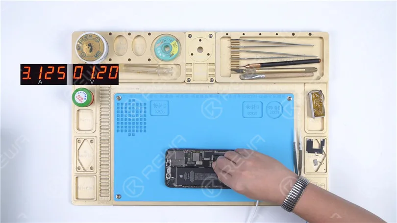
Desconecte los cables flexibles. Retire la bandeja de la tarjeta SIM.
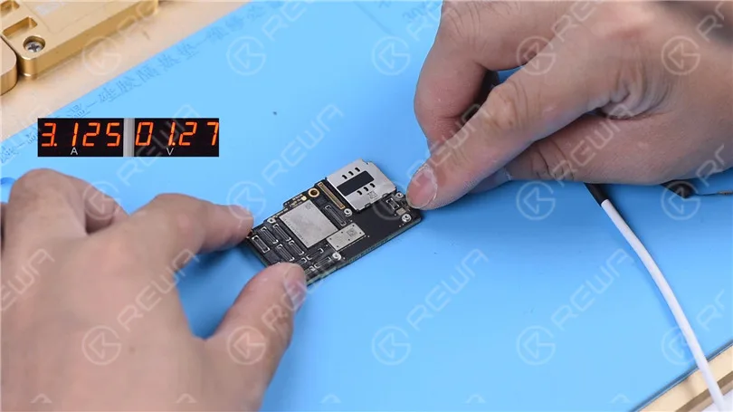
Separe la placa base. Conecte de nuevo la placa base con el cable de alimentación.
El amperímetro sigue mostrando una gran corriente de 3,1 A.
Indica que la gran corriente no tiene nada que ver con otros cables flexibles.
El fallo está en la placa base.
Medición en modo diodo
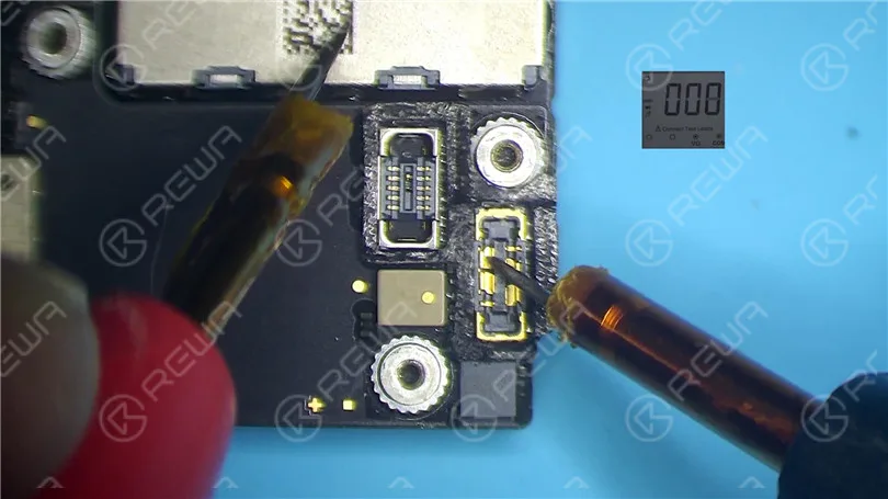
Realice la medición en modo diodo del pin 1 en el J7010 del conector de la batería.
El valor del diodo es 0. Indica que el circuito principal de alimentación está cortocircuitado a masa.
Dado que el circuito alimenta simultáneamente la placa lógica y la placa de señales, necesitamos separar la placa base para localizar el fallo.
Separación de la placa base
Retire la espuma de la placa base.
Caliente la parte posterior de la placa base con la pistola de aire caliente a 240 grados centígrados.
Retire el papel protector.
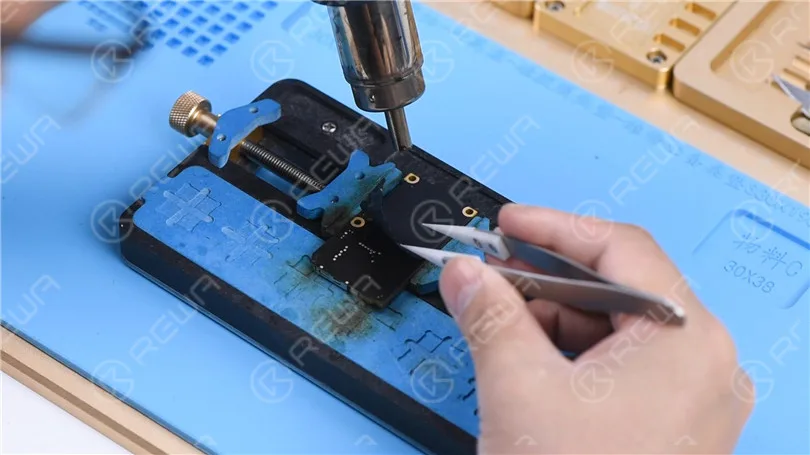
Coloque la placa base en el Plataforma de calefacción.
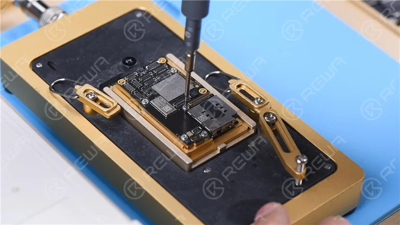
Para facilitar la extracción de la placa lógica tras la separación, atornille un tornillo en la placa lógica.
Ajuste la temperatura de la Plataforma Calefactora a 185 grados centígrados.
Sujete el tornillo para retirar la placa lógica cuando la temperatura haya alcanzado los 185 grados centígrados. Retire la placa de señales.
Medición en modo diodo
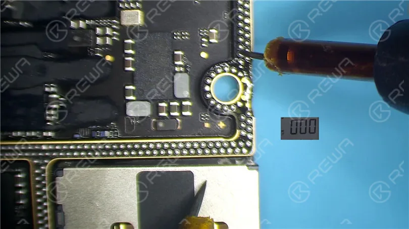
Ejecute la medición en modo diodo del pin 286 de la placa de señales. El valor del diodo es 0.
Indica que la fuente de alimentación principal de la tarjeta de señal está en cortocircuito a masa.
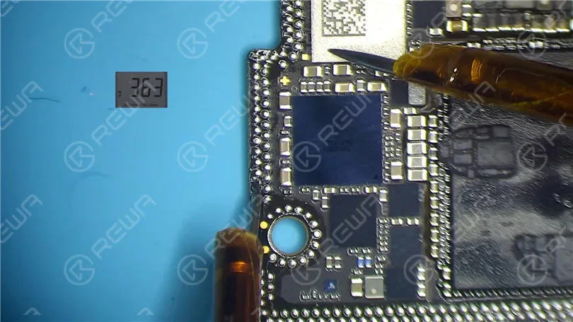
Mide el pin 286 de la placa lógica.
El valor del diodo es 363, lo que significa que la placa lógica es normal.
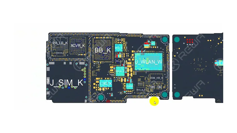
Abra el mapa de bits. Podemos ver que hay muchos componentes asociados en el circuito principal de alimentación.
Detección de colofonia
A continuación, hay que localizar el componente defectuoso con el detector de colofonia.
Elimine la grasa térmica con un cuchillo de esculpir.
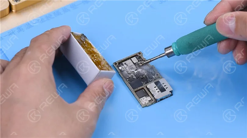
Sumerja la colofonia con el soldador a 365 grados centígrados.
Fume colofonia en la placa de señales. Ajuste la alimentación de corriente continua a 4,1 V.
Conecte el ánodo positivo y negativo de la alimentación de corriente continua con sondas de multímetro.
Conecte la sonda negra a tierra.
Conecte la sonda roja a la patilla 286 de la placa de señales.
Podemos ver que la colofonia en C1200 K se ha derretido. Esto indica que el condensador está dañado.
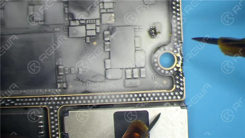
Después lo calentamos con la pistola de aire caliente a 350 grados centígrados. Retiramos el condensador con unas pinzas.
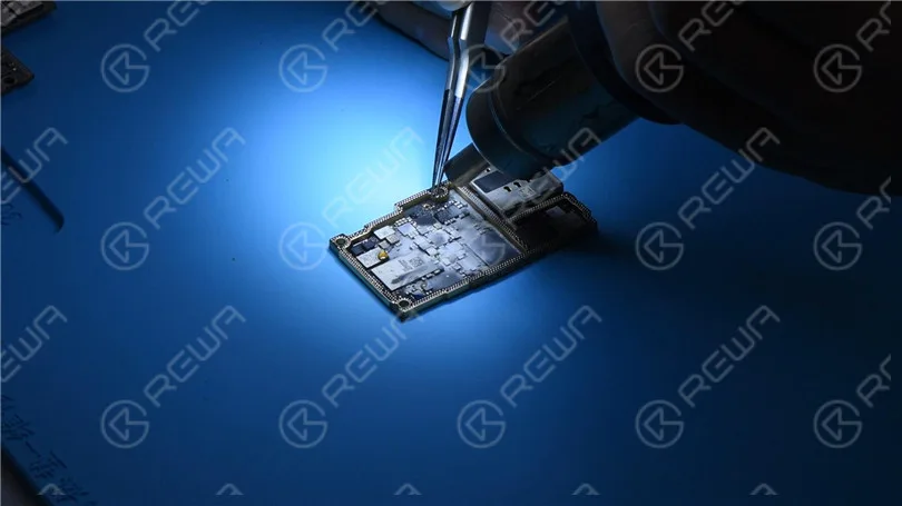
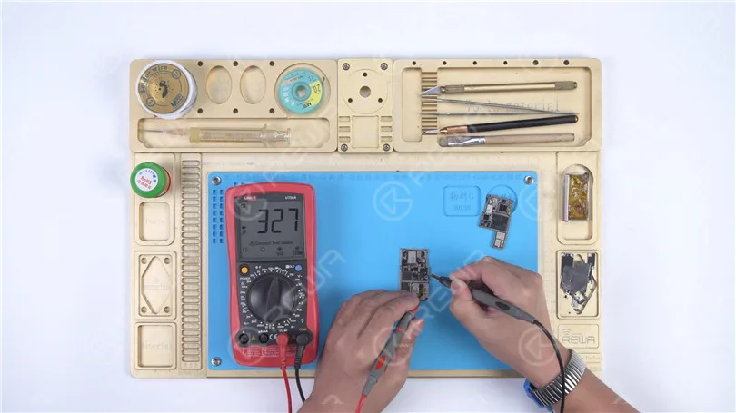
Limpie la colofonia de la placa de señal con PCB Cleaner. Realice una segunda medición en modo diodo. El valor del diodo vuelve a un valor normal de 327.
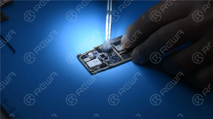
Recombinación de placas base
Unte colofonia con el soldador y la mecha de soldadura a 365 grados centígrados para eliminar el estaño de la almohadilla de unión.
Limpie la placa de señal con PCB Cleaner. Retire el estaño y limpie la placa lógica con el mismo método.
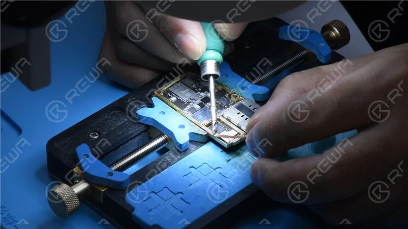
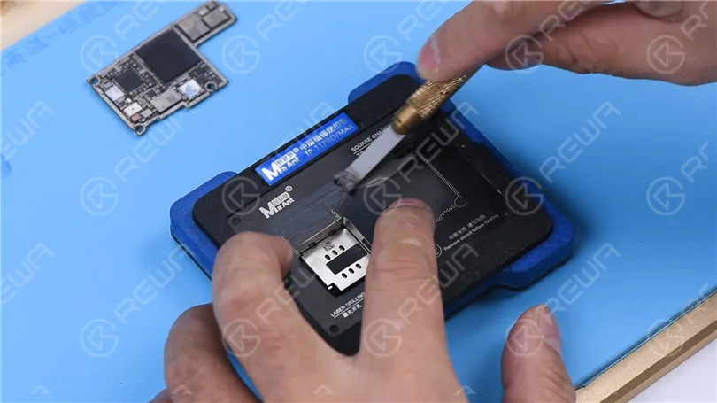
Fije el tablero de señales a la plataforma de reequilibrado.
Coloque la plantilla de reballing en posición. Para evitar que la pasta de soldadura fluya hacia las hendiduras de la placa base, inserte una placa metálica.
Aplique una capa de Pasta de Soldadura de baja temperatura.
Retire la plantilla de reballing.
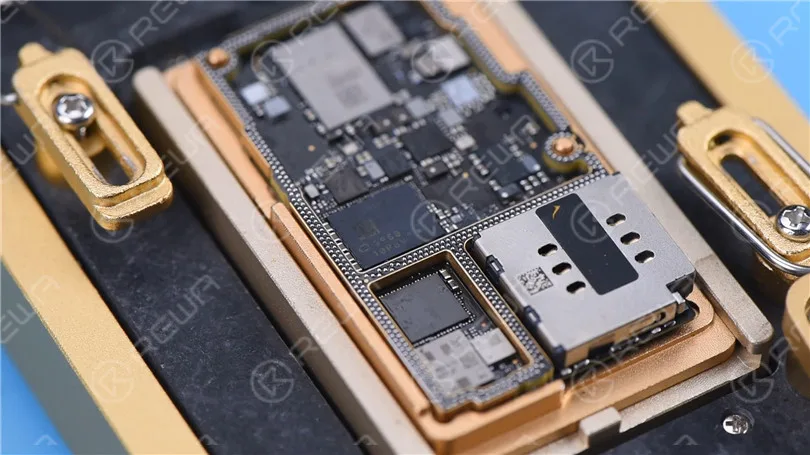
Coloque la placa de señales en la plataforma calefactora a 185 grados centígrados para calentarla.
Una vez formadas las bolas de soldadura, apague la alimentación y enfríe la placa base durante 5 minutos.
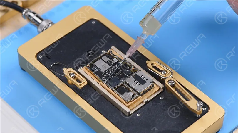
Aplique un poco de fundente en pasta.
Alinee la placa lógica con la placa de señales.
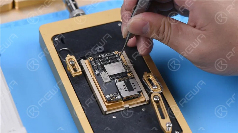
Mantenga el calentamiento en la Plataforma Calefactora a 185 grados centígrados.
Cuando la temperatura alcance los 185 grados centígrados, seguir calentando durante 1 minuto.
Este paso sirve para asegurarse de que la placa lógica y la placa de señales encajan perfectamente.
Pruebas
Conecte la placa base con el cable de alimentación.
Cortocircuite a masa el pin 12 del J7700. La corriente de arranque se normaliza.
Pon la placa base en el teléfono.
Conecta los cables flexibles. Conecta la pantalla y la batería.
Porque la batería está agotada. Enchufe el cable de carga y el teléfono se enciende normalmente.
-
Reparar iPhone X sin servicio saltando un cable
El iPhone X no tiene banda base, número IMEI ni servicio. Mira este video para ver cómo solucionamos el problema haciendo puentes.
-
Cómo reparar iPhone 7 botón de inicio no funciona después de daños por agua
Water damage is a common issue for iPhone in daily use. In this video, the home button of iPhone 7 is not working after water damaged, because lines on logic board get corroded and damaged. Since there is a high failure risk in repairing, REWA LAB presents you a method to fix heavily corroded and damaged logic board step by step by Ultrasonic Cleaner and making jumper wire. To fix your iPhone 7 home button issue caused by water damage, please follow the repair operations of our tutorial video.
-
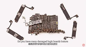
Servicio de reparación de placas lógicas de iPhone/iPad/MacBook REWA
¿Te has quedado sin ideas con tus placas lógicas defectuosas? ¿No sabes cómo manejar las reparaciones difíciles? ¿Por qué no recurrir a REWA? Llevamos ofreciendo servicios de reparación de placas lógicas a nivel de chip para iPhone, iPad y MacBook. Expertos profesionales y técnicas pueden liberarte de reparaciones pesadas y difíciles. Con solo 5 pasos, podemos resolver casi todos los problemas de reparación de placas base de tu iPhone, iPad y MacBook. Veamos el video para conocer los detalles.
-
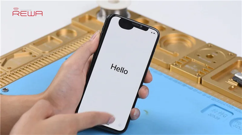
iPhone X Unresponsive Touch Screen Repair
Our course today is about iPhone X touchscreen unresponsive repair.
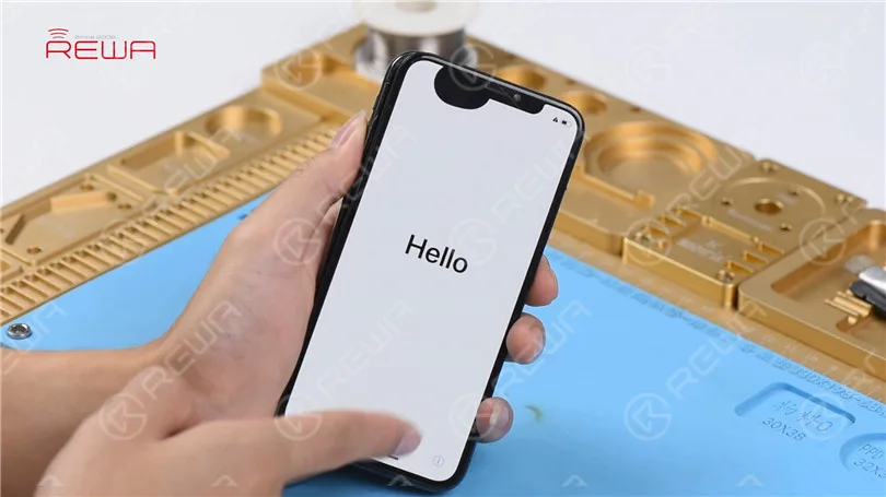
Press the power button to turn on the phone. The phone turns on normally. Touch screen of the phone is unresponsive.
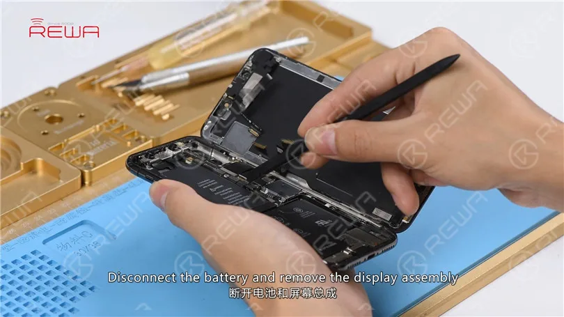
Turn off the phone and take apart it. Disconnect the battery and remove the display assembly.
Take out the motherboard. The first thing we do is to check the Touch ID FPC connector J5800. Run diode mode measurement of J5800. The measured value of Pin 22 is OL which indicates that Pin 22 relevant circuit has open-circuited.
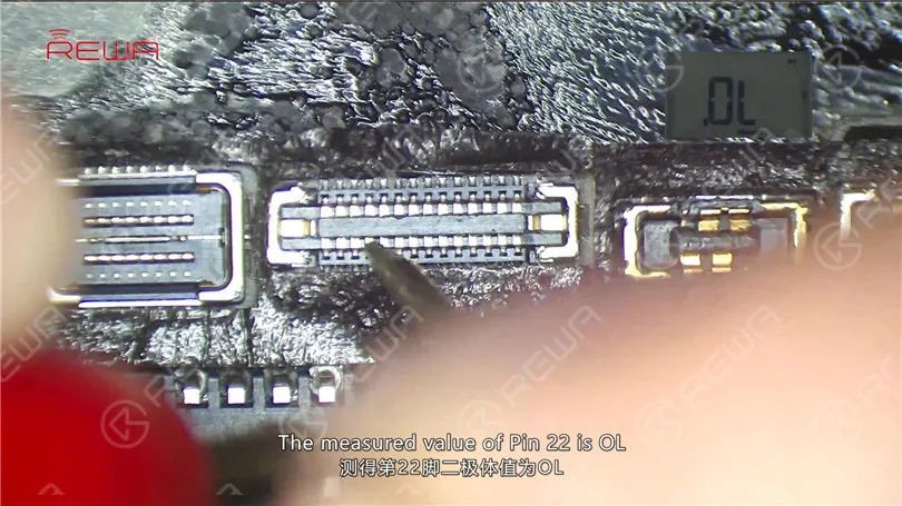
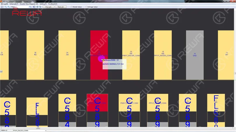
We can see that there is an inductor FL5893 on the circuit. Let’s start with FL5893.
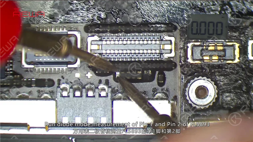
First, remove sponge around J5800 with tweezers. Run diode mode measurement of Pin 1 and Pin 2 of FL5893. The measured value of the two pins is 0. Judging by the measured value, FL5893 is in normal status.
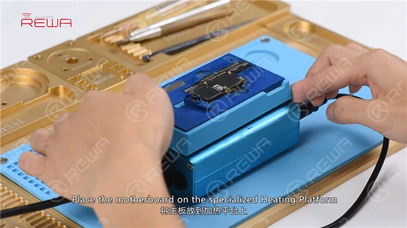
We can see that the circuit makes its way to the third space PCB. So we need to separate the motherboard to check the third space PCB. Place the motherboard on the specialized Heating Platform. With temperature of the platform reaching 160℃, pick up the upper layer with tweezers.
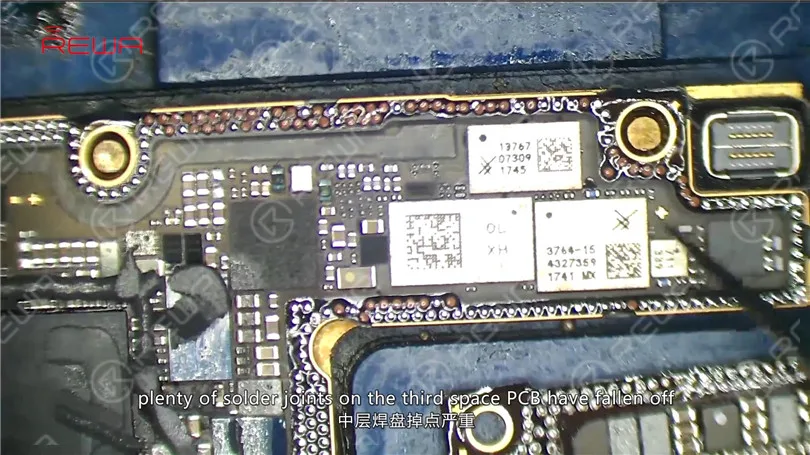
As you can see, plenty of solder joints on the third space PCB have fallen off. And the motherboard is severely deformed. Judging by this, the motherboard is unrepairable.
Conclusión:
iPhone X touchscreen is unresponsive. The first thing we do is to check the Touch ID FPC connector J5800. Run diode mode measurement of J5800. Judging by the measured value, Pin 22 relevant circuit has open-circuited. We can see on the bitmap that the circuit makes its way to the third space PCB. Separate the motherboard and we find that plenty of solder joints on the third space PCB have fallen off. The motherboard is also severely deformed. Judging by this, the motherboard is unrepairable.
-
How to Fix iPhone X Bottom Speaker Not Working
Today we will share how to fix iPhone X bottom speaker not working.
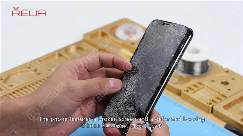
The phone features a broken screen and a deformed housing. Get a new display assembly installed and test. The phone turns on normally. Both the front camera and the rear camera work normally. WiFi also functions well.
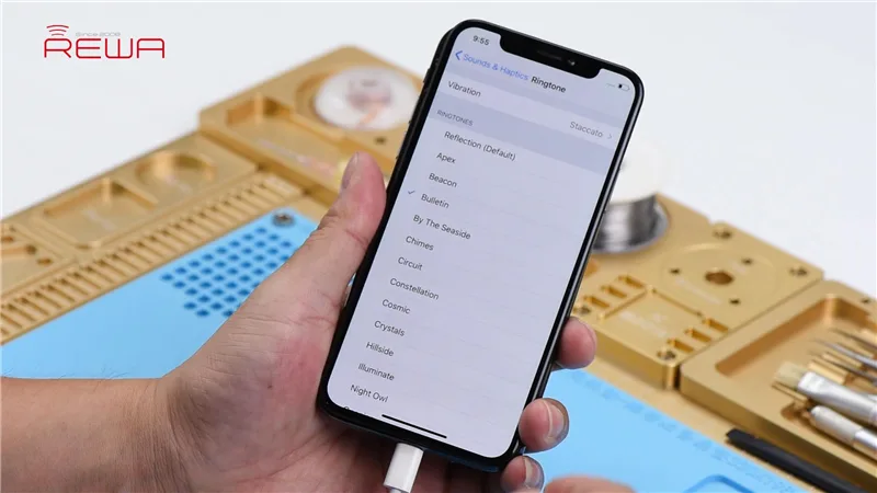
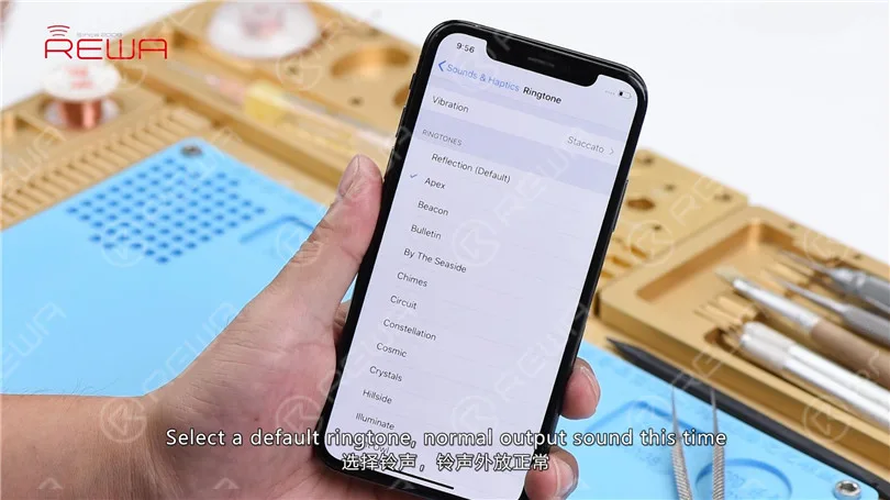
Go to Sounds & Haptics > Ringtone. Select a default ringtone and there is no output sound. But the sound works fine with headphones in.
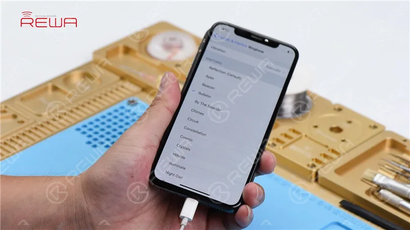
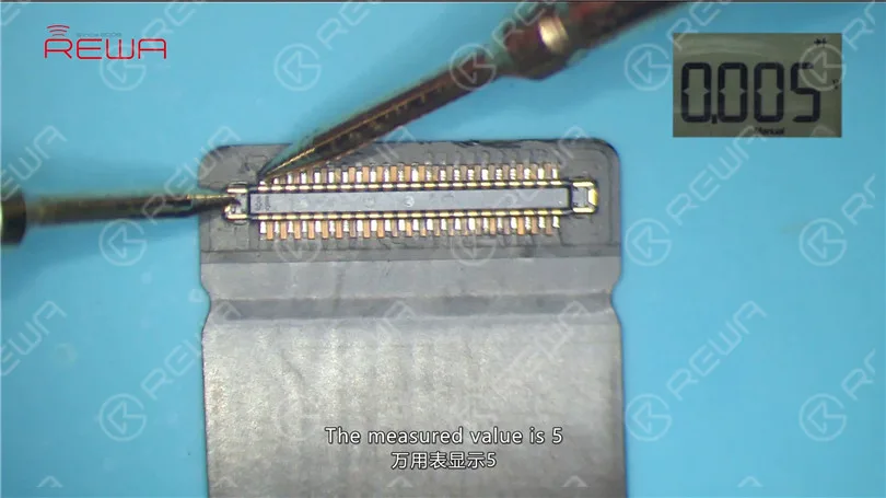
The preliminary judgment is that the audio circuit is in normal condition. It’s just that the bottom speaker is not working. Remove the display assembly and disconnect the battery. Disconnect the charging port flex cable. Run diode mode measurement of Pin 1 and Pin 45 of the DOCK connector. The measured value is 5, which indicates that the bottom speaker is in normal condition.
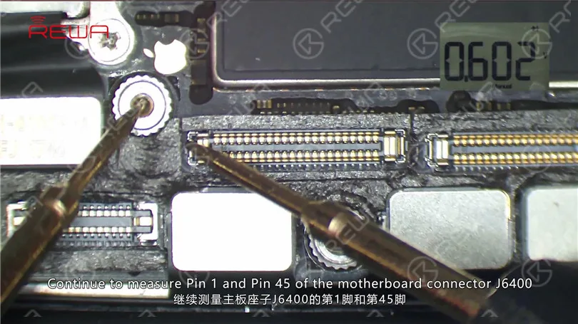
Continue to measure Pin 1 and Pin 45 of the motherboard connector J6400. The measured value of Pin 45 is 602, which is normal.
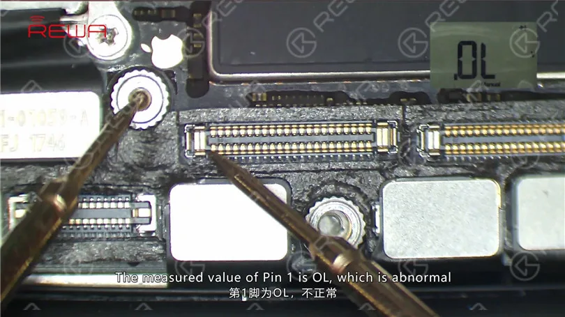
The measured value of Pin 1 is OL, which is abnormal.
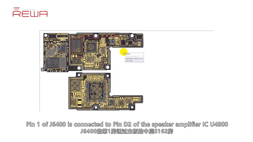
Judging by this, Pin 1 relevant circuit has been open-circuited. Pin 1 of J6400 is connected to Pin 2 of the speaker amplifier IC U4900 by way of Pin S162 on cylinders around the edge of the lower layer. So our next move is to check the circuit carefully. Disconnect flex cables on the motherboard and take out the motherboard. Fix the motherboard to the Holder. Heat with Hot Air Gun at 360℃, air flow 65.
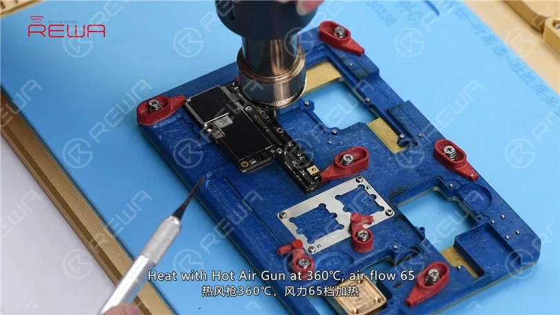
One minute later, pry up the upper layer step by step. Tips: make sure you pry up the upper layer at the right moment when tins on cylinders have melted. We can see clearly that there are multiple missing pins on the upper layer, including Pin S166 of the NFC circuit.
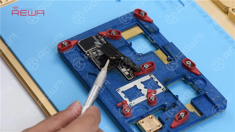
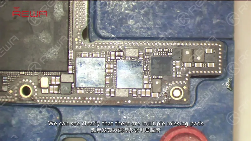
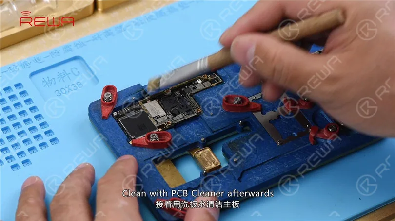
Judging by this, the phone has been dropped, which resulted in pseudo soldering of the motherboard accompanied with the detachment of pins. Since most of those missing pins are ground pins, we can just ignore them. Yet we need to treat Pin S166 with jumper wiring. Remove tins on cylinders around the edge of the lower layer and bonding pads of the upper layer with rosin soaked Solder Wick. Clean with PCB Cleaner afterwards.
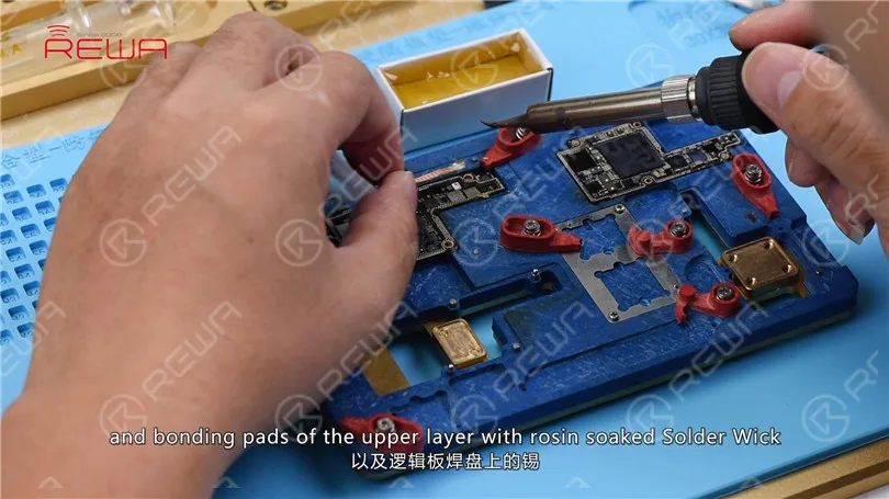
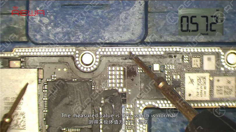
Run diode mode measurement of Pin S162 on cylinders. The measured value is 570, which is normal. Continue to measure Pin S163. The measured value is 570, which is normal. Judging by this, the open-circuited condition of Pin 1 relevant circuit is caused by pseudo soldering of cylinders around the edge of the lower layer.
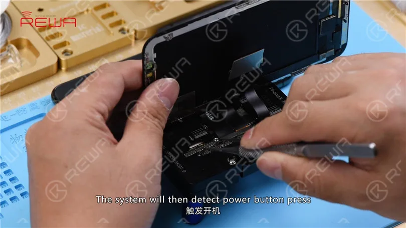
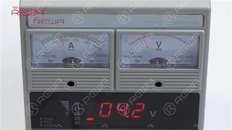
Now, let’s get the motherboard installed to the testing kit. Buckle up the extension flex cable of the display assembly. Then the charging port flex cable and the display assembly. Connect the battery connector with the DC Power Supply. Short Pin 9 of J4300 to the ground with tweezers. The system will then detect power button press. Current reading on the ammeter is normal.
Go to Settings > Sounds & Haptics > Ringtone. Select a default ringtone. Normal output sound this time.
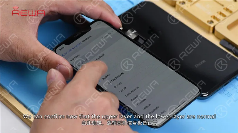
We can confirm now that the upper layer and the lower layer are normal. And the fault is caused by pseudo soldering of cylinders. We can fix the problem by soldering the two layers together. Also before soldering, we need to treat Pin S166 with jumper wiring. Apply tins to the Via with Soldering Iron at 360℃. Prepare a length of tin applied Enameled Copper Wire of 0.02mm in diameter. Solder one end to the tin applied Via.
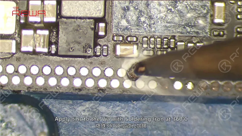
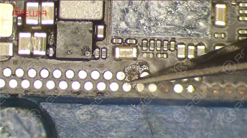
Clean with PCB Cleaner afterwards. Then apply some UV Curable Solder Mask to the soldered area. And solidify the upper layer under Lámpara de secado UV for 2 minutes.
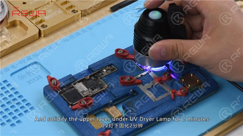
Then get the other end to the right position. Next, attach the lower layer to PCB Holder. Fix the BGA Reballing Stencil to the right position. Smear Soldering Paste evenly on the BGA reballing stencil with BGA Scraper. Wipe out excess Soldering Paste with lint-free wiping cloth.
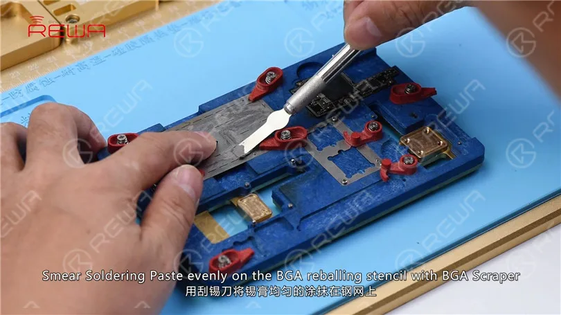
Then heat evenly with Hot Air Gun at 350℃, air flow 35. So that all solder balls can solidify completely. Remove the BGA reballing stencil after 2 minutes. Heat again with Hot Air Gun to ensure the formation of solder balls.
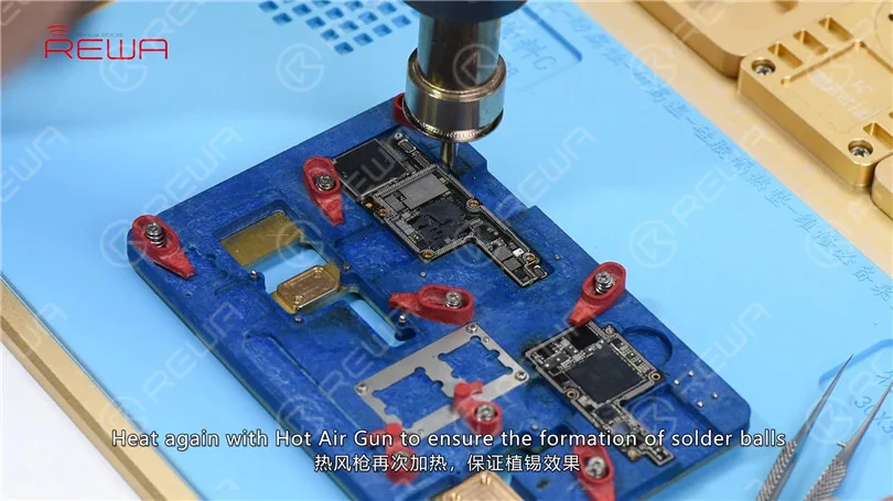
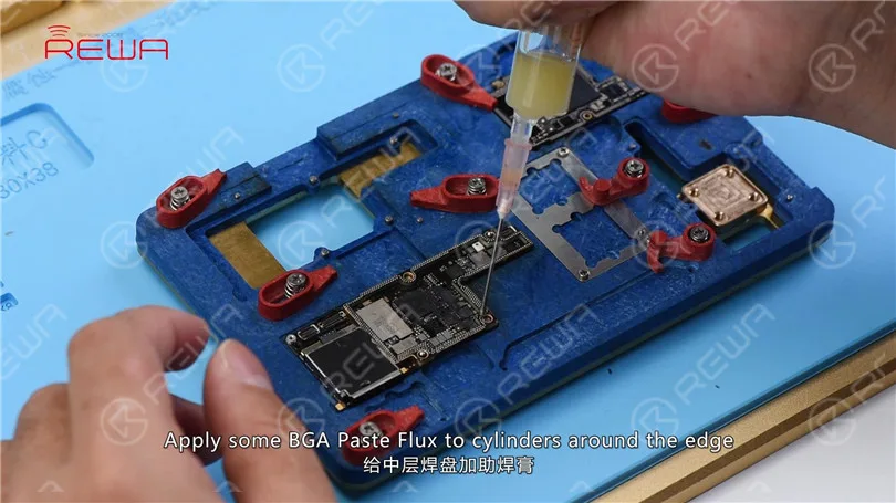
Apply some BGA Paste Flux to cylinders around the edge and get the upper layer in position.
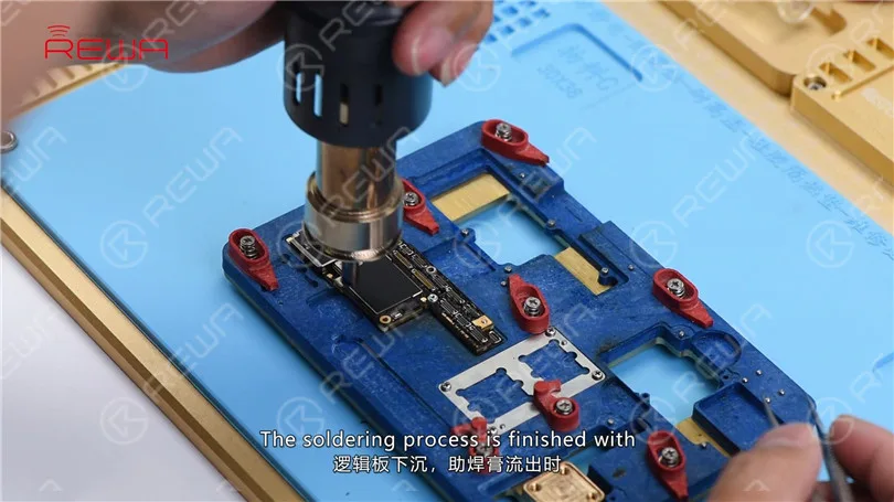
Heat evenly with Hot Air Gun at 350℃, air flow 65. The soldering process is finished with the upper layer sinking and Paste Flux overflowing.
Wait for the motherboard to cool for 5 minutes. Now, let’s assemble the phone and test. Go to Settings>Sounds&Haptics>Ringtone. Select a default ringtone, normal output sound this time.
-
REWA Deep Test para la pantalla LCD del iPhone X Aftermarket
Many people in the cell phone repair industry have expectations for iPhone X aftermarket screen to reduce the repair cost of iPhone X screen repair. Since iPhone X is different with previous models, the difficulty of iPhone X aftermarket screen production is quite high. After fully tested the first batch of iPhone X LCD aftermarket screens, REWA shares our test results with you for your information.
-
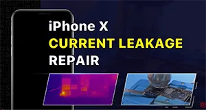
Cómo solucionar que la batería del iPhone X se agote rápido: el fallo se esconde bajo el lector de tarjetas
The iPhone X battery is draining fast with an overheating issue. After measurement, the motherboard is found to have a current leakage. Since the current is too small, rosin detecting is unable to find the fault. Therefore, we use a thermal imager to find the faulty part. After multiple checks, the faulty part is found to be under the card reader.
-
Reparación de la placa base del iPhone
The iPhone Motherboard Repair Live Course is suitable for iPhone motherboard repair beginners. The course includes troubleshooting methods and demo repair for common motherboard problems. In the meantime, we offer continuous technical support for your learning. Join REWA Academy live course on 6 Sept to enrich your repair knowledge.
-
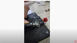
Conoce por dentro el motor Taptic del iPhone
A combination of “tap” and “haptic feedback,” Taptic Engine is a technology that Apple creates to provide tactile sensations in the form of vibrations to users. So what’s inside of the Taptic Engine? Check out this video to find out!
 English
 Español
 Français
 Deutsch
 Italiano