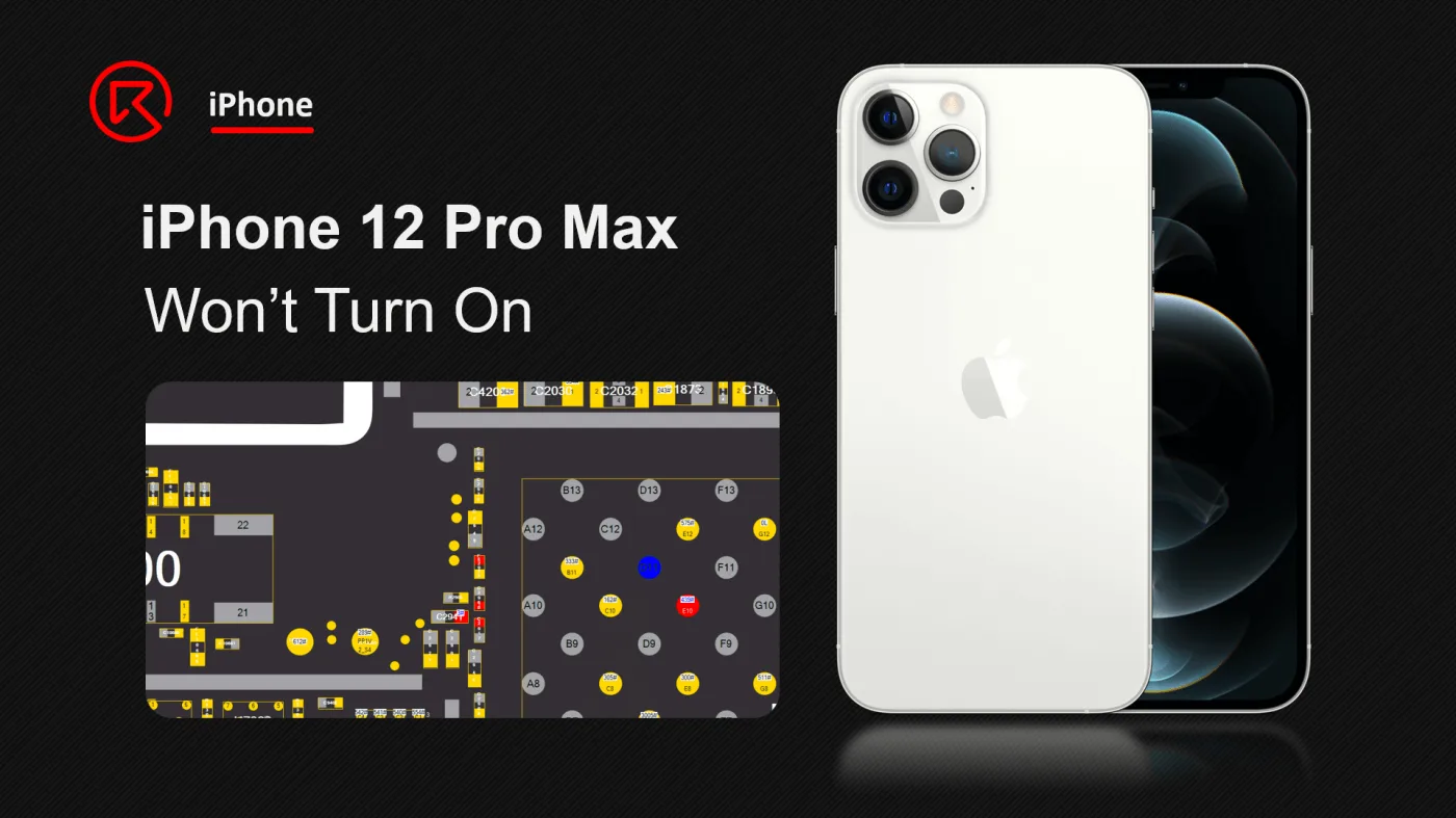
Schlagwort: iphone won’t turn on

  • Reparaturanleitung für das Problem, dass sich das iPhone 12 Pro Max nicht einschalten lässt

    iPhone 12 Pro Max schaltet sich nicht ein Problem Reparaturanleitung

    Das iPhone 12 Pro Max, das am 13. Oktober 2020 angekündigt wurde, ist ein High-End-Smartphone, das für seine fortschrittlichen Funktionen bekannt ist. Ein schwerer Sturz kann jedoch dazu führen, dass es sich nicht mehr einschalten lässt. Diese Anleitung beschreibt die Schritte zur Fehlerbehebung und Reparatur dieses Problems.

    iphone 12 pro max cannot charge stuck apple logo

    Telefon Details

    Modell: iPhone 12 Pro Max

    Angekündigt: 2020, Oktober 13

    Defekt-Phänomen

    Ein iPhone 12 Pro Max, das durch einen Sturz schwer beschädigt wurde, lässt sich möglicherweise nicht mehr einschalten. In solchen Fällen kann das folgende Verfahren zur Fehlerbehebung und Reparatur hilfreich sein.

    Prozess der Fehlersuche

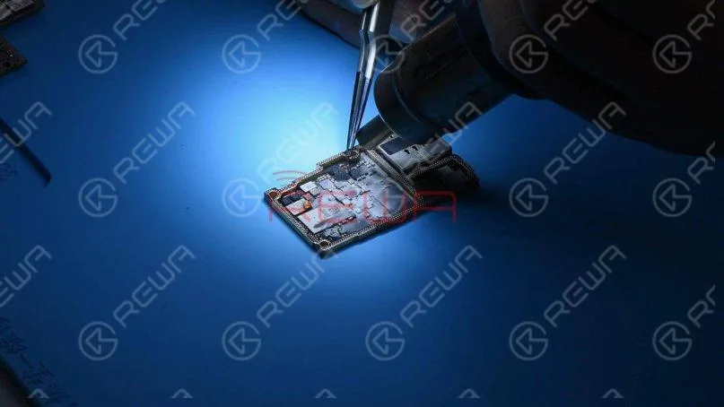
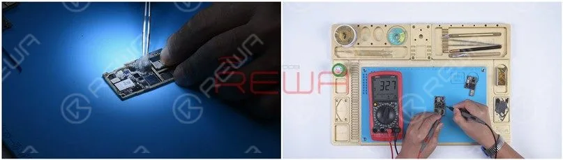
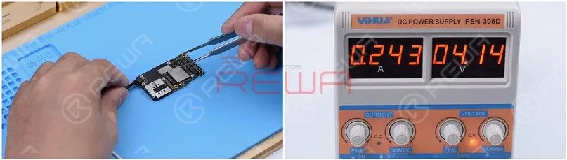
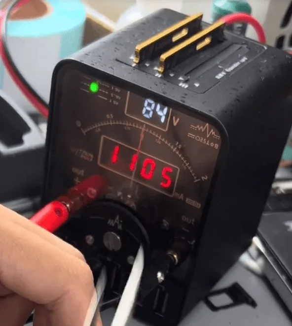
    Schließen wir zunächst das Motherboard an das DC-Netzteil an, so tritt kein Strom aus. Aber wenn man den Bootvorgang mit der Pinzette auslöst, springt der Strom direkt auf 1100mA.
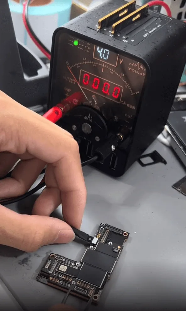
    iphone 12 pro max won turn issue repair guide trigger to boot
    iphone 12 pro max won turn issue repair guide 1100ma directly

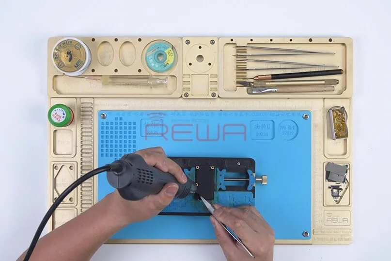
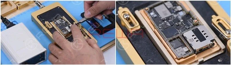
    Als Nächstes entfernen wir die Schaumstoffe um die Anschlüsse und halten dann die Hauptplatine auf die Heizplattform, um die beiden Schichten der Hauptplatine zu trennen.
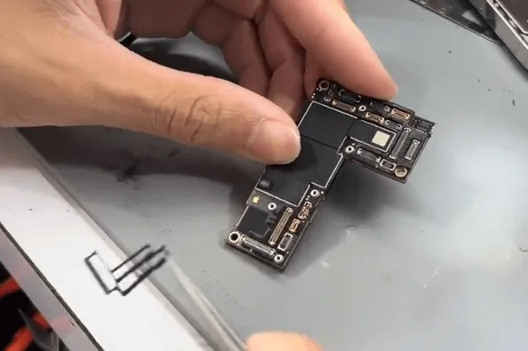
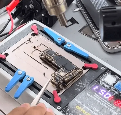
    iphone 12 pro max won turn issue repair guide remove the foams around
    iphone 12 pro max won turn issue repair guide separate with the heating

    Nach der Trennung ist es nicht verwunderlich, dass viele Polster abgefallen sind, und wir müssen uns später viel Zeit nehmen, um die fehlenden Polster zu reparieren. Aber wie auch immer, lassen Sie uns zuerst das Problem mit dem Stiefel beheben.

    Bei der Messung der Diodenwerte auf den Stromschienen, die von der PMU an die CPU ausgegeben werden, wird festgestellt, dass ein Kondensator in der Nähe der CPU mit der Masse kurzgeschlossen ist.
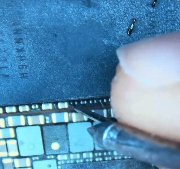
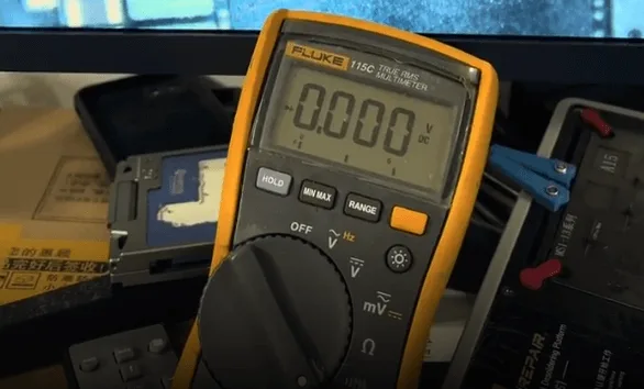
    iphone 12 pro max won turn issue repair guide when measuring with
    iphone 12 pro max won turn issue repair guide find one rail is shorted

    Siehe dazu die Refox-Bitmapheißt es PP1V2_IO.

    Wie wir sehen können, gibt es viele Komponenten, die mit dem PP1V2_IO zusammenhängen.
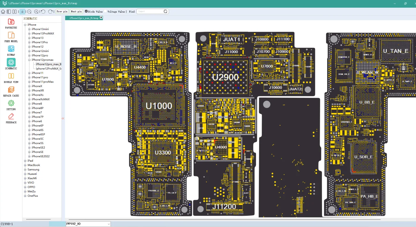
    iphone 12 pro max won turn issue repair guide refox bitmap

    Um das genaue kurzgeschlossene Bauteil herauszufinden, müssen wir die Methode der Kolophoniumprüfung anwenden.

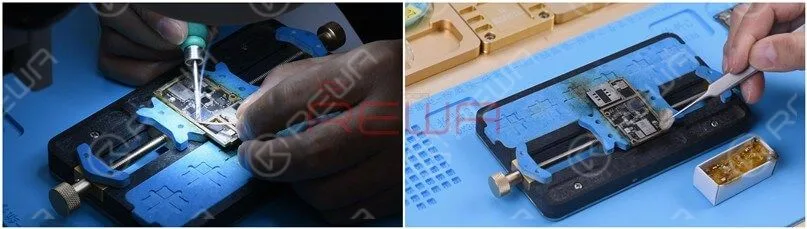
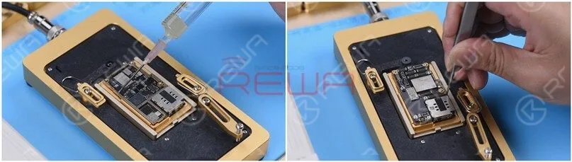
    Tragen Sie Kolophoniumrauch auf die Oberfläche der entsprechenden Bereiche der Hauptplatine auf.
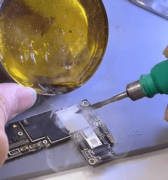
    iphone 12 pro max won turn issue repair guide apply rosin smoke on the

    Verbinden Sie dann die Hauptplatine mit der DC-Stromversorgung Maschine und überprüfen Sie unter dem Mikroskop, können wir die kurzgeschlossene Komponente leicht zu finden.
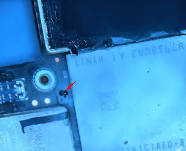
    iphone 12 pro max won turn issue repair guide the shorted capacitor

    Siehe die Bitmap, es ist der Kondensator C2941
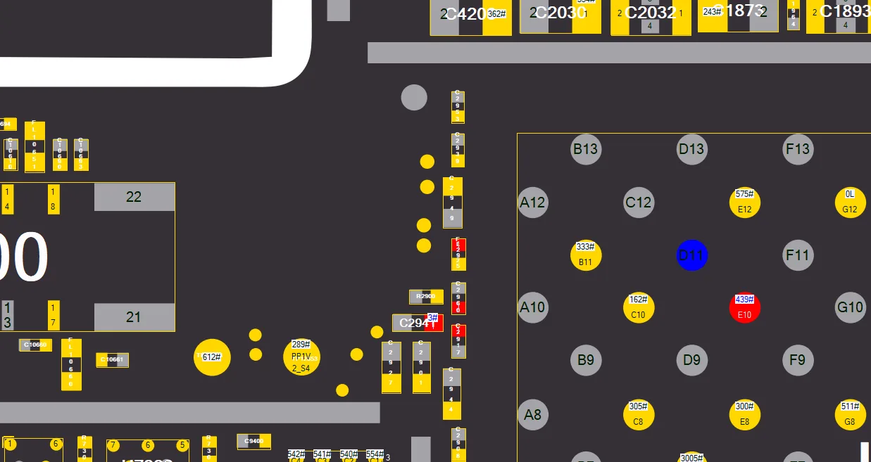
    iphone 12 pro max won turn issue repair guide c2941

    Da es sich um einen Filterkondensator handelt, können wir mögliche Hitzeschäden am NAND und den Anschlüssen vermeiden. Wir können ihn einfach direkt mit einer Pinzette herausnehmen.

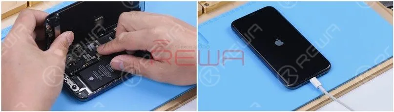
    Verbinden Sie danach die Logikplatine mit dem Bildschirm und booten Sie mit dem DC-Netzteil wieder, das Telefon kann gebootet werden.
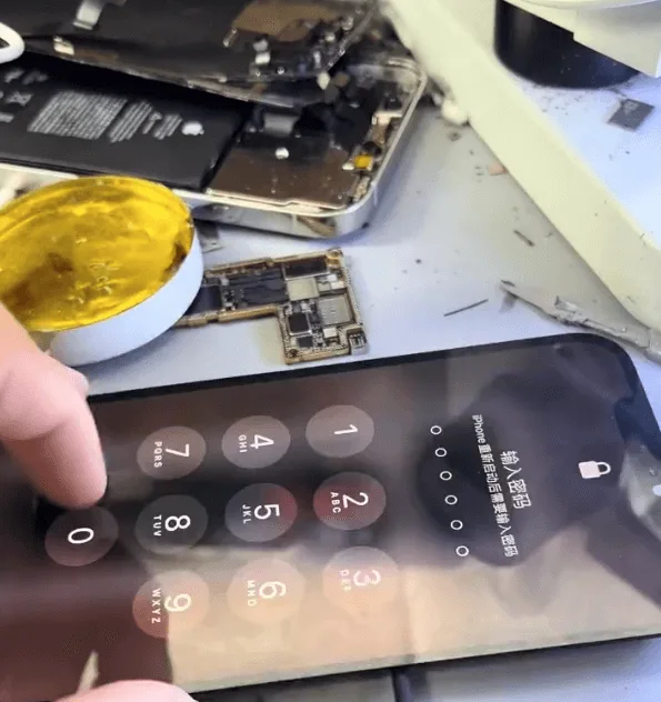
    iphone 12 pro max won turn issue repair guide phone can be booted

    Reparieren wir dann die fehlenden Pads auf der mittleren Ebene.
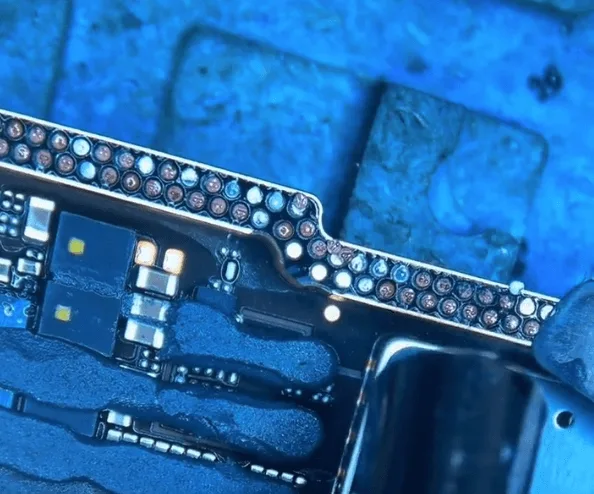
    iphone 12 pro max won turn issue repair guide the missing pads on middle

    Die Reparatur der fehlenden Polster ist nicht sehr schwierig, erfordert aber viel Geduld.

    Für das Pad, das keinen Anschlusspunkt hat
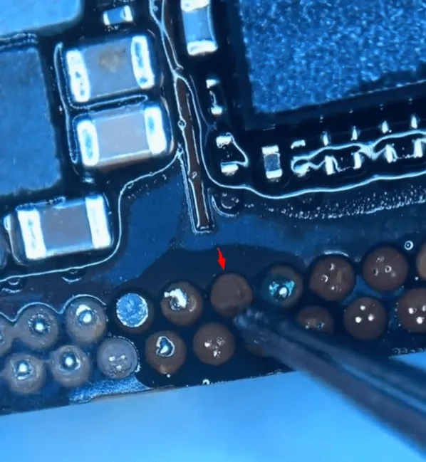
    iphone 12 pro max won turn issue repair guide for the pad that has no

    Wir müssen zuerst die Wurzel der Unterlage mit einem Bildhauermesser etwas auskratzen
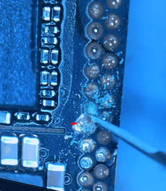
    iphone 12 pro max won turn issue repair guide scratch out the pads

    Danach, basierend auf der "Wurzel" zu springen Draht und machen einen Kreis
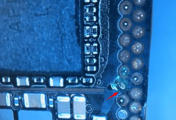
    iphone 12 pro max won turn issue repair guide make circle

    Dann eine Kupferlasche auf die Oberfläche löten
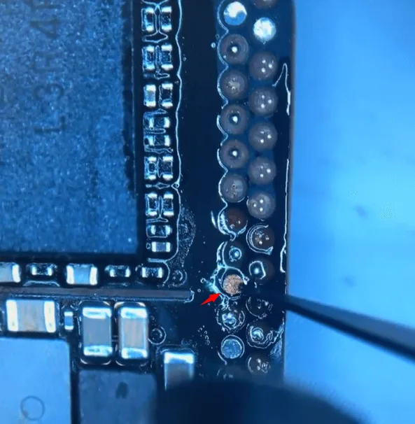
    iphone 12 pro max won turn issue repair guide solder copper lug on the

    Dann härten Sie es aus und verstärken es mit der UV-Maske und der UV-Lampe.
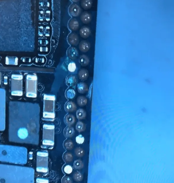
    iphone 12 pro max won turn issue repair guide cure with the uv lamp

    Zusammenbau und Test

    Montieren Sie dann die beiden Lagen der Grundplatine zuerst mit der Heizplattform
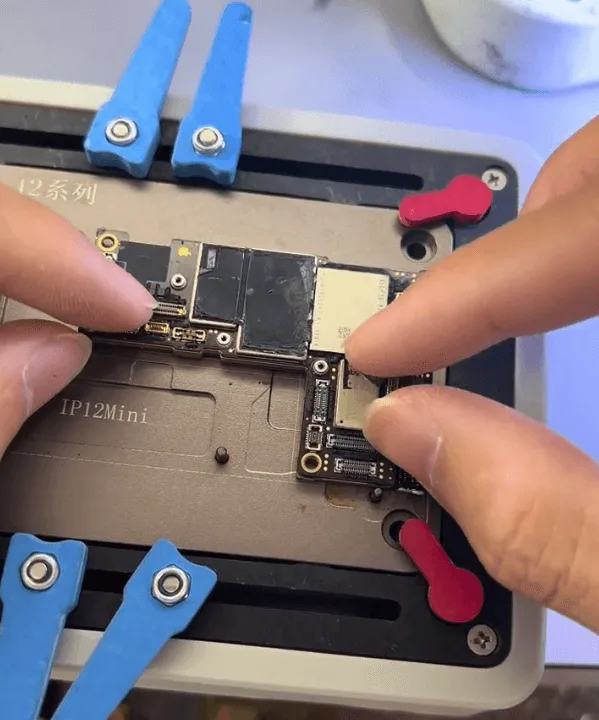
    iphone 12 pro max won turn issue repair guide heating platform

    Wenn die Hauptplatine abgekühlt ist, setzen Sie das Telefon zusammen, um es zu testen, und alle Funktionen sind in Ordnung.

    Das Problem wird behoben, indem der beschädigte Kondensator entfernt und die beiden Schichten der Hauptplatine wieder zusammengefügt werden.
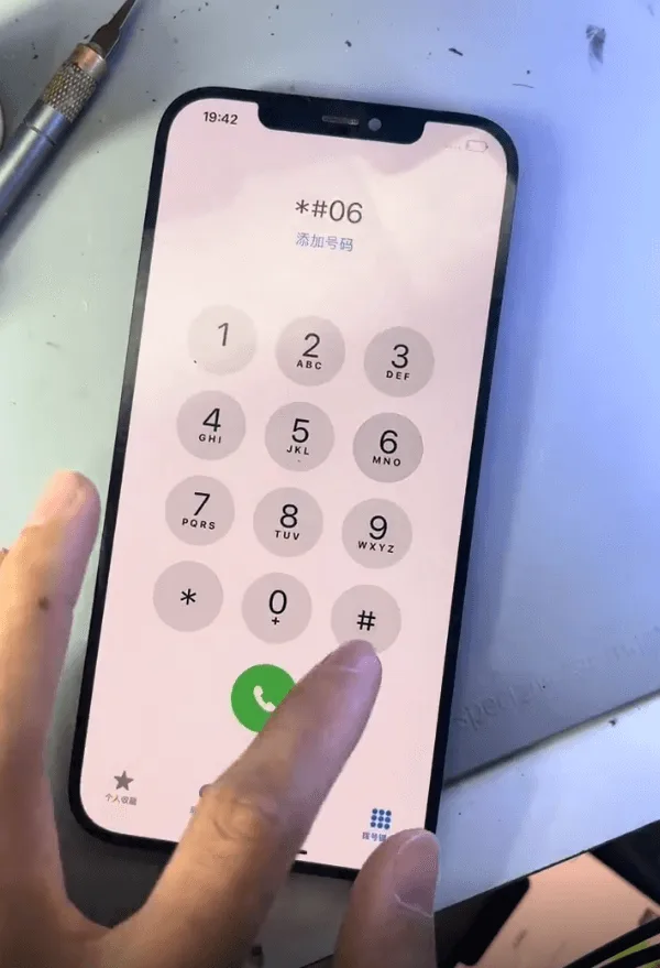
    Das iPhone 12 Pro Max lässt sich nicht einschalten

    Zusammenfassung

    Das Problem, dass sich das iPhone 12 Pro Max aufgrund eines schweren Sturzschadens nicht mehr einschalten lässt, wurde von uns behoben:

    • Entfernen des beschädigten Kondensators (C2941).
    • Die beiden Schichten der Hauptplatine werden wieder zusammengefügt.
    • Ausbessern der fehlenden Polster.

    Diese Reparatur erfordert eine sorgfältige Inspektion und präzise Arbeit, um sicherzustellen, dass das Telefon wieder voll funktionsfähig ist, ohne weitere Schäden zu verursachen.
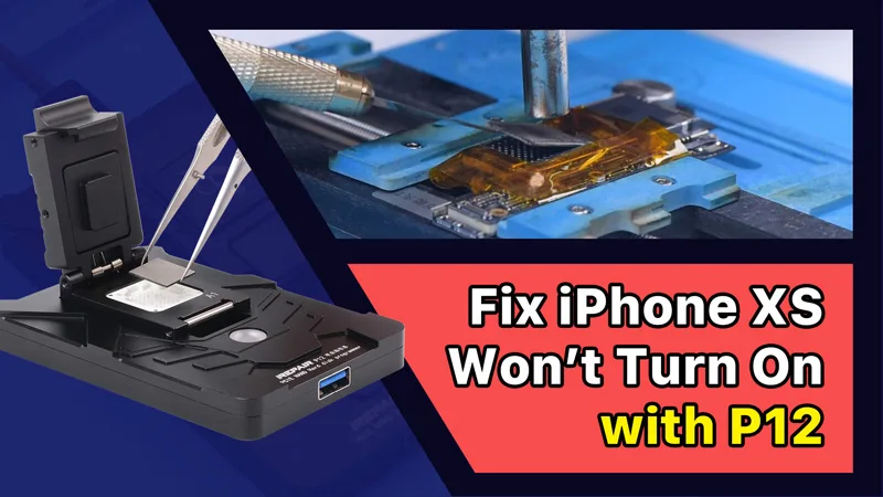
  • iPhone XS lässt sich mit P12 (NAND-Programmierer für iPhone 6 – iPhone 11 Pro Max) nicht einschalten

    iPhone XS lässt sich mit P12 (NAND-Programmierer für iPhone 6 – iPhone 11 Pro Max) nicht einschalten

    Der NAND-Austausch ist ein gängiges Verfahren bei der iPhone-Reparatur, sei es für ein Speicherupgrade oder zur Behebung von Problemen wie dem Nicht-Einschalten, die durch ein beschädigtes NAND verursacht wurden. Für den NAND-Austausch ist ein NAND-Programmierer erforderlich, um die NAND-Daten zu lesen und zu schreiben.

    iPhone XS schaltet sich nicht ein reparieren mit P12 (NAND Programmer für iPhone 6 - iPhone 11 Pro Max)

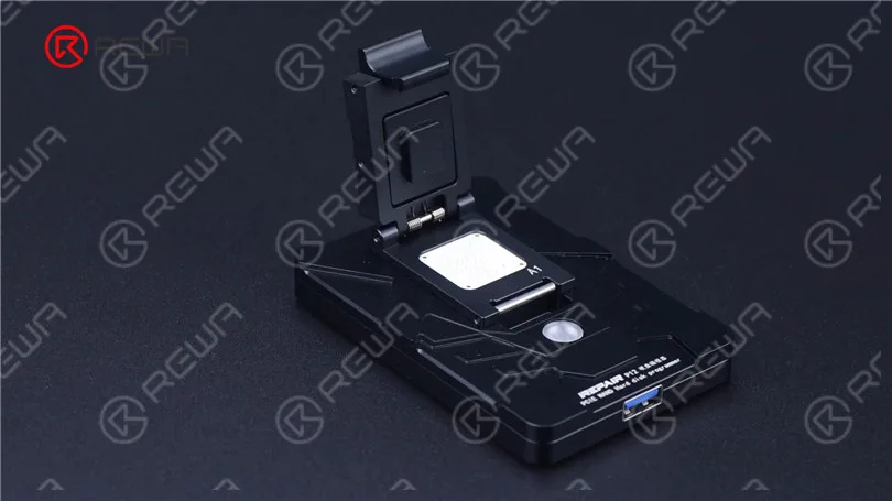
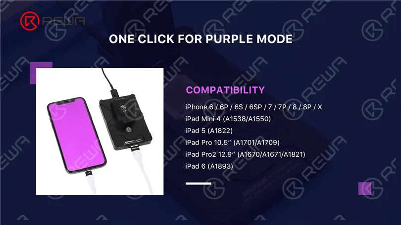
    Heute reparieren wir ein iPhone mit dem neuesten NAND-Programmierer P12, Im Vergleich zu anderen NAND-Programmierern auf dem Markt unterstützt der P12 eine breite Palette von Modellen, einschließlich NAND-Lesen und -Schreiben sowie WLAN-Entbindung für das iPhone 6 bis iPhone 11 Pro Max und einige iPad-Modelle. Darüber hinaus kann der P12 ohne Internetverbindung arbeiten und ist dauerhaft kostenlos nutzbar.

    iPhone XS schaltet sich nicht ein reparieren mit P12 (NAND Programmer für iPhone 6 - iPhone 11 Pro Max)
    iPhone XS schaltet sich nicht ein reparieren mit P12 (NAND Programmer für iPhone 6 - iPhone 11 Pro Max)
    iPhone XS schaltet sich nicht ein reparieren mit P12 (NAND Programmer für iPhone 6 - iPhone 11 Pro Max)

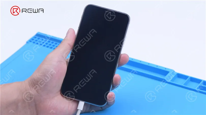
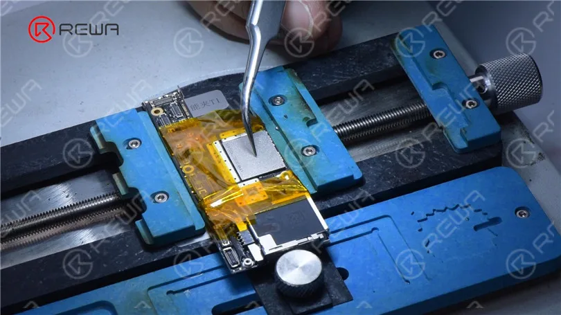
    Dann verwenden wir P12, um ein iPhone XS zu reparieren, das sich nicht einschalten lässt. Das iPhone XS kann nicht hochfahren.

    iPhone XS schaltet sich nicht ein reparieren mit P12 (NAND Programmer für iPhone 6 - iPhone 11 Pro Max)

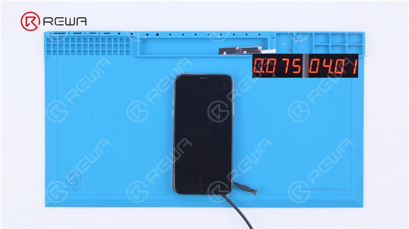
    Dann demontieren wir das Telefon für weitere Tests. Verbinden Sie das Mainboard mit Netzkabel. Der Boot-Strom beträgt nur 75 mA. Es kann vorläufig beurteilt werden, dass das System fehlerhaft ist.

    iPhone XS schaltet sich nicht ein reparieren mit P12 (NAND Programmer für iPhone 6 - iPhone 11 Pro Max)

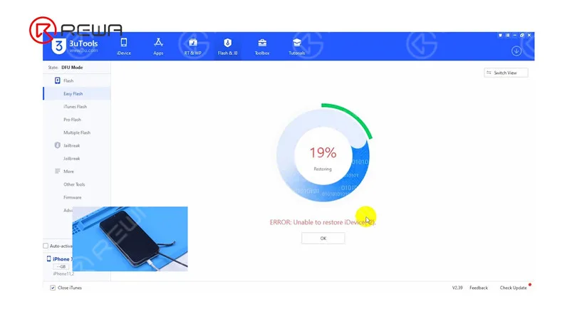
    Verbinden Sie anschließend das Telefon mit dem Computer. Das Telefon befindet sich automatisch im DFU-Modus. Der Flash-Vorgang bleibt bei 19% hängen. Wir können nun bestätigen, dass das Problem, dass sich das Gerät nicht einschalten lässt, durch fehlerhafte Schaltkreise im Zusammenhang mit dem NAND-Speicher verursacht wird.

    iPhone XS schaltet sich nicht ein reparieren mit P12 (NAND Programmer für iPhone 6 - iPhone 11 Pro Max)

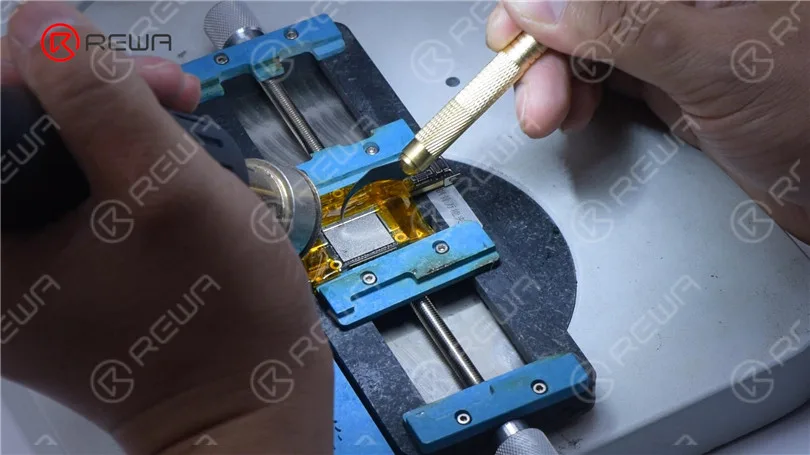
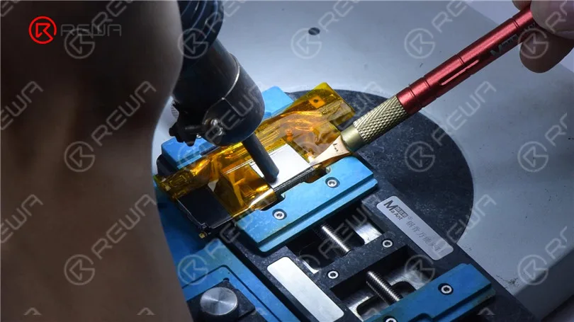
    Der nächste Schritt besteht darin, den NAND durch einen neuen zu ersetzen. Entfernen Sie das Display und trennen Sie die Hauptplatine ab. Bringen Sie Hochtemperaturklebeband um die Hauptplatine herum an. Entfernen Sie zunächst den schwarzen Klebstoff um den NAND herum mit einer Heißluftpistole bei 280 °C.

    iPhone XS schaltet sich nicht ein reparieren mit P12 (NAND Programmer für iPhone 6 - iPhone 11 Pro Max)

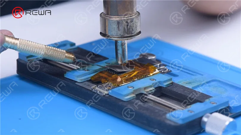
    Hebe den NAND mit einer Heißluftpistole bei 400 °C ab.

    iPhone XS schaltet sich nicht ein reparieren mit P12 (NAND Programmer für iPhone 6 - iPhone 11 Pro Max)

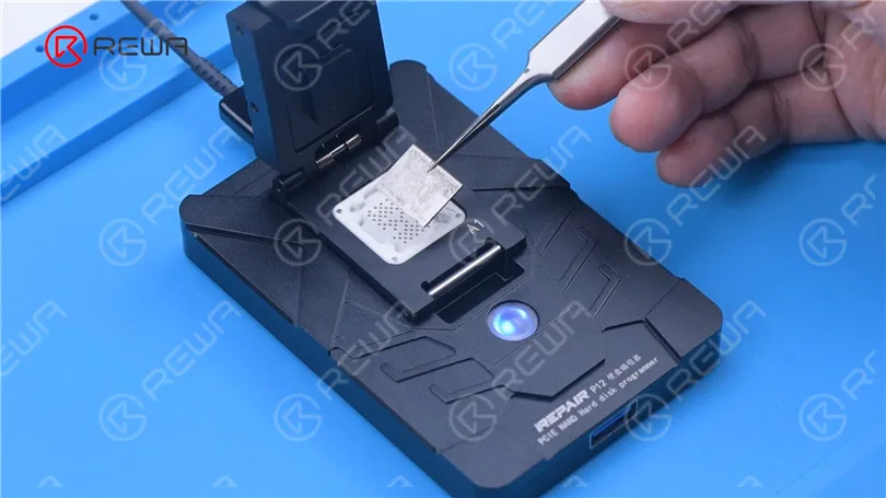
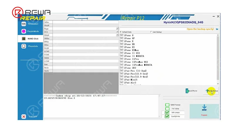
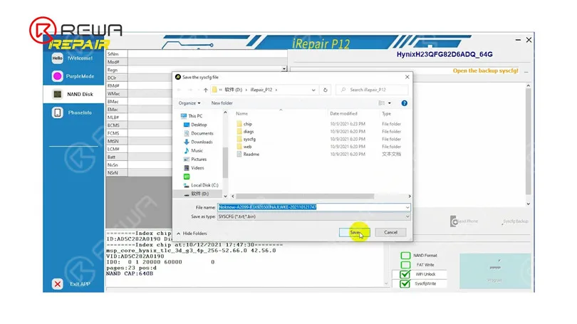
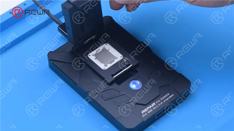
    Schließen Sie das NAND an P12 an. Achten Sie darauf, das NAND am A1-Pin auszurichten. Klicken Sie auf “Syscfg Backup”. Speichern Sie dann die Daten.

    iPhone XS schaltet sich nicht ein reparieren mit P12 (NAND Programmer für iPhone 6 - iPhone 11 Pro Max)
    iPhone XS schaltet sich nicht ein reparieren mit P12 (NAND Programmer für iPhone 6 - iPhone 11 Pro Max)
    iPhone XS schaltet sich nicht ein reparieren mit P12 (NAND Programmer für iPhone 6 - iPhone 11 Pro Max)

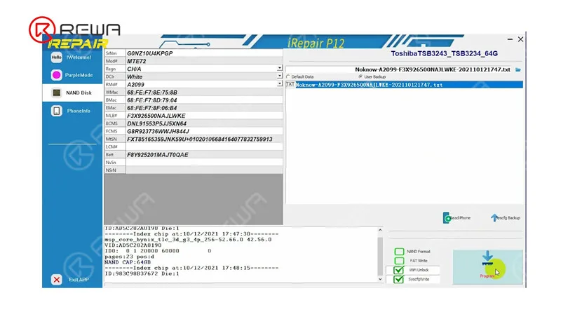
    Entfernen Sie das NAND. Bringen Sie das neue NAND an P12 an. Wählen Sie “User Backup”. Tippen Sie auf “Program”.

    iPhone XS schaltet sich nicht ein reparieren mit P12 (NAND Programmer für iPhone 6 - iPhone 11 Pro Max)
    iPhone XS schaltet sich nicht ein reparieren mit P12 (NAND Programmer für iPhone 6 - iPhone 11 Pro Max)

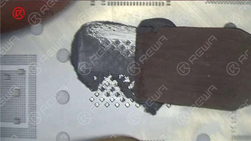
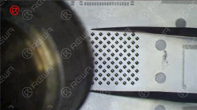
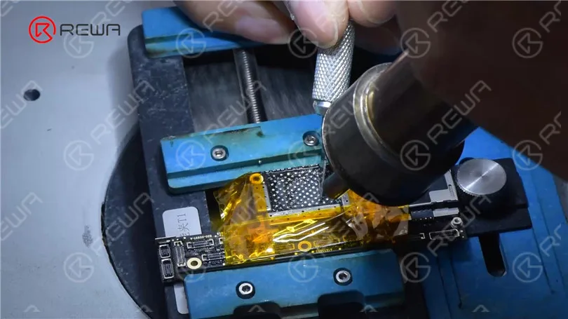
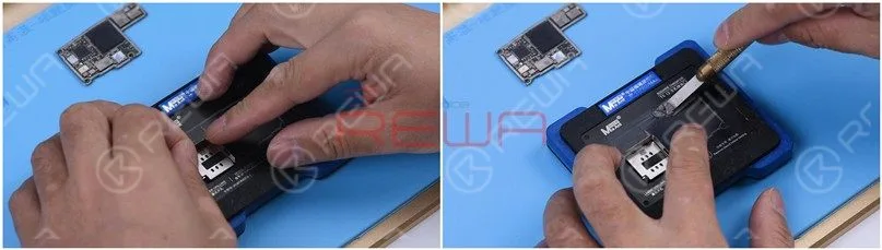
    Als Nächstes führen wir das Reballing des NAND mit den beschriebenen Daten durch. Setzen Sie die Reballing-Schablone in Position. Tragen Sie eine Schicht Mitteltemperatur-Lötpaste gleichmäßig auf. Erhitzen Sie mit einer Heißluftpistole bei 340 °C.

    iPhone XS schaltet sich nicht ein reparieren mit P12 (NAND Programmer für iPhone 6 - iPhone 11 Pro Max)
    iPhone XS schaltet sich nicht ein reparieren mit P12 (NAND Programmer für iPhone 6 - iPhone 11 Pro Max)

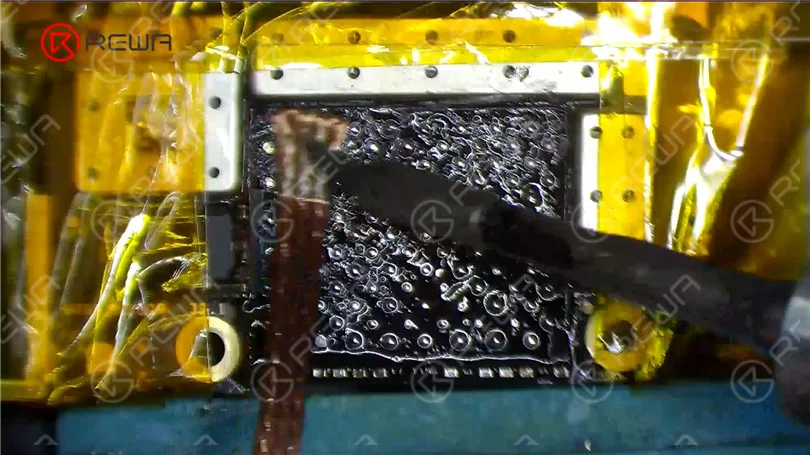
    Vor dem NAND-Löten müssen wir das Zinn von den Lötpads entfernen. Tragen Sie etwas Mitteltemperatur-Lötpaste mit dem Lötkolben auf. Reinigen Sie die Lötpads mit Lötkolben und Entlötlitze.

    iPhone XS schaltet sich nicht ein reparieren mit P12 (NAND Programmer für iPhone 6 - iPhone 11 Pro Max)

    Entfernen Sie den schwarzen Klebstoff auf den Bonding-Pads mit einem Skalpell. Reinigen Sie dann die Bonding-Pads mit PCB-Reiniger. Tragen Sie nach der Reinigung etwas Paste Flux auf.

    Richten Sie den neuen NAND aus. Zum Löten mit der Heißluftpistole bei 380 °C erhitzen.

    iPhone XS schaltet sich nicht ein reparieren mit P12 (NAND Programmer für iPhone 6 - iPhone 11 Pro Max)
    iPhone XS schaltet sich nicht ein reparieren mit P12 (NAND Programmer für iPhone 6 - iPhone 11 Pro Max)

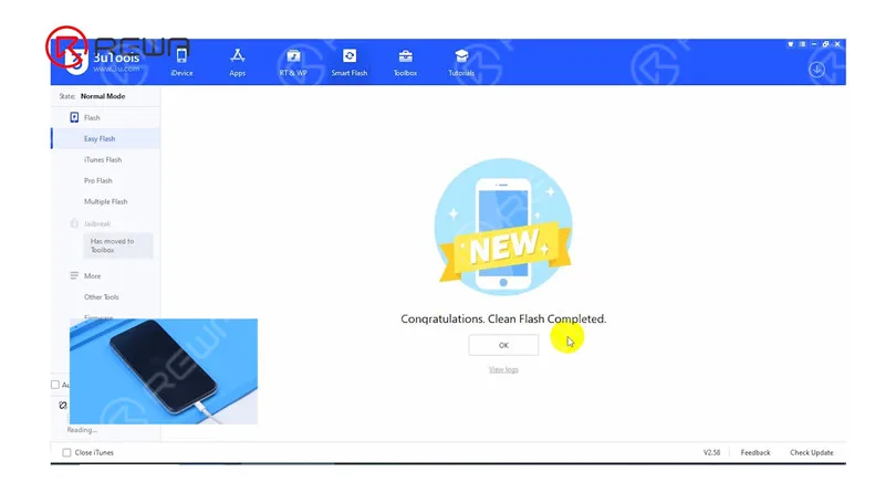
    Dann installieren wir das Mainboard. Verbinden Sie das Telefon mit dem Computer, um es zu flashen. Das Flashen war erfolgreich.
    iPhone XS schaltet sich nicht ein reparieren mit P12 (NAND Programmer für iPhone 6 - iPhone 11 Pro Max)

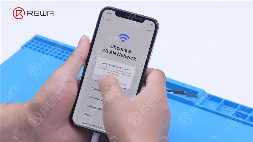
    Das Telefon lässt sich normal einschalten. Nach der Aktivierung funktioniert das Telefon ebenfalls gut.
    iPhone XS schaltet sich nicht ein reparieren mit P12 (NAND Programmer für iPhone 6 - iPhone 11 Pro Max)
  • Fix iPhone 7/7 Plus Won’t Turn On – CPU Repair

    Fix iPhone 7/7 Plus Won’t Turn On – CPU Repair

    iPhone 7/7 Plus won’t turn on after it is dropped? Due to the imperfect technology of CPU supplier, the SDRAM of iPhone 7/7 Plus series can be easily damaged. Once dropped, the SDRAM might be short circuited and the phone won’t turn on afterwards. The traditional SDRAM replacing method is complex and easy to get it pseudo soldered. This time we introduced a new solution with CNC Chip Grinding Machine. Let’s check the video to see how we fix iPhone 7 plus won’t power on issue in a more efficient way.

  • Fix iPhone 12 Won’t Turn On By Infrared Thermal Imaging Camera

    Fix iPhone 12 Won’t Turn On By Infrared Thermal Imaging Camera

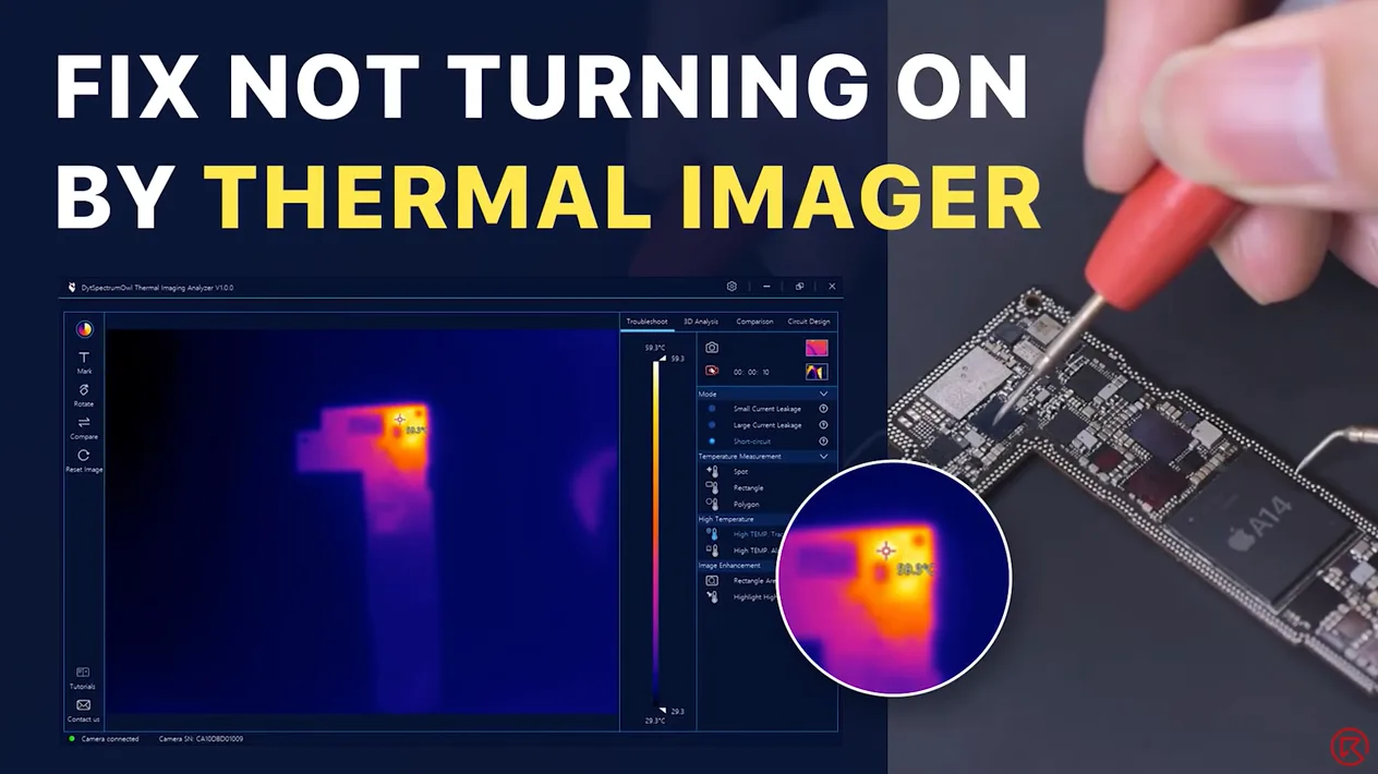
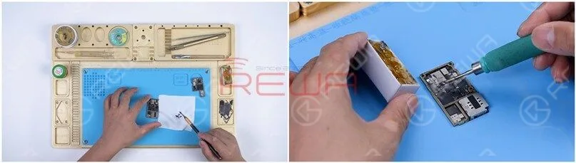
    Today we will share a repair case of an iPhone 12 that won’t turn on. After multiple attempts to turn on the iPhone 12, the iPhone 12 still won’t turn on. We have excluded the possibility of the display assembly and battery faults, so we speculate the cause is the short circuit of the motherboard. To find the faulty part, we have used the latest infrared thermal imager camera that differs from the complicated rosin detecting. Let’s check it out!
  • How to Fix an iPhone 11 Pro Won’t Turn On

    How to Fix an iPhone 11 Pro Won’t Turn On

    Having trouble with your iPhone 11 Pro refusing to turn on? Don’t worry, we’ve got your back! In this comprehensive guide, we’ll walk you through some practical and effective solutions to fix this frustrating issue.

    Step 1: Disassemble and test

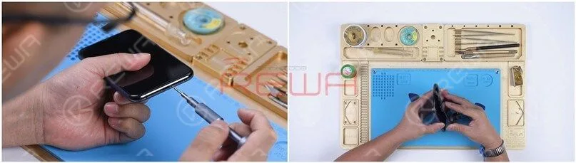
    Remove the two pentalobe screws at the bottom edge and lift the screen.
    Remove the two pentalobe screws at the bottom edge and lift the screen.

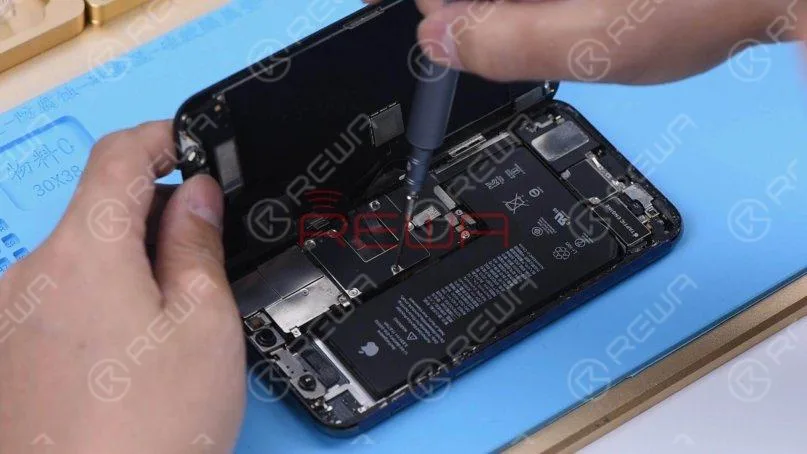
    After the screen is lifted, take the shielding covers off, disconnect the battery, and remove the screen.
    After the screen is lifted, take the shielding covers off, disconnect the battery, and remove the screen.

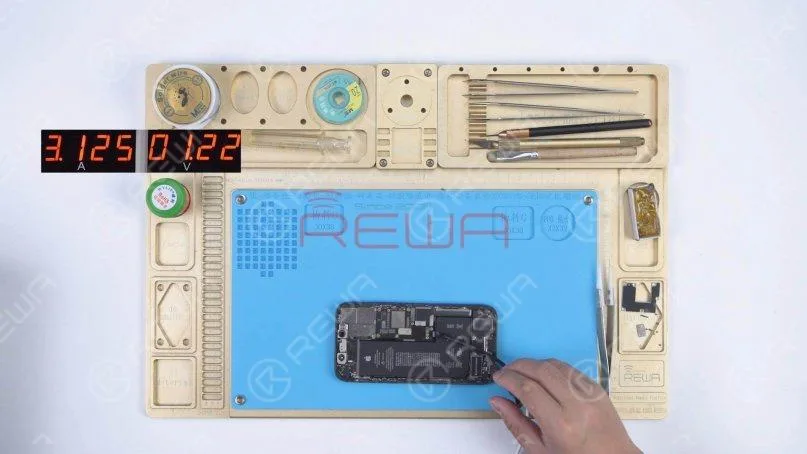
    Connect the motherboard with the Power Cable. The ammeter shows a large current of 3.1A.
    Connect the motherboard with the Power Cable. The ammeter shows a large current of 3.1A.

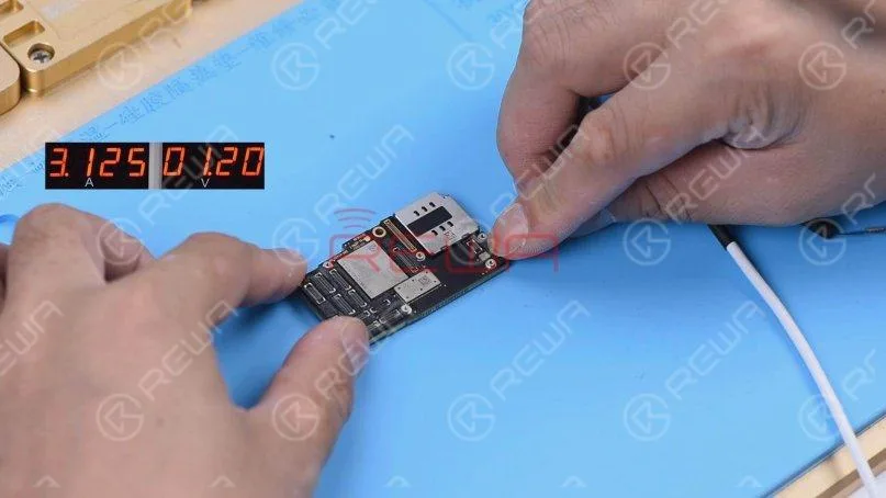
    Detach the motherboard and connect the motherboard with the Power Cable again. The ammeter still shows a large current of 3.1A.
    Detach the motherboard and connect the motherboard with the Power Cable again. The ammeter still shows a large current of 3.1A.

    It indicates that the large current has nothing to do with other flex cables. The fault is on the motherboard.

    Schritt 2: Messung im Diodenmodus durchführen

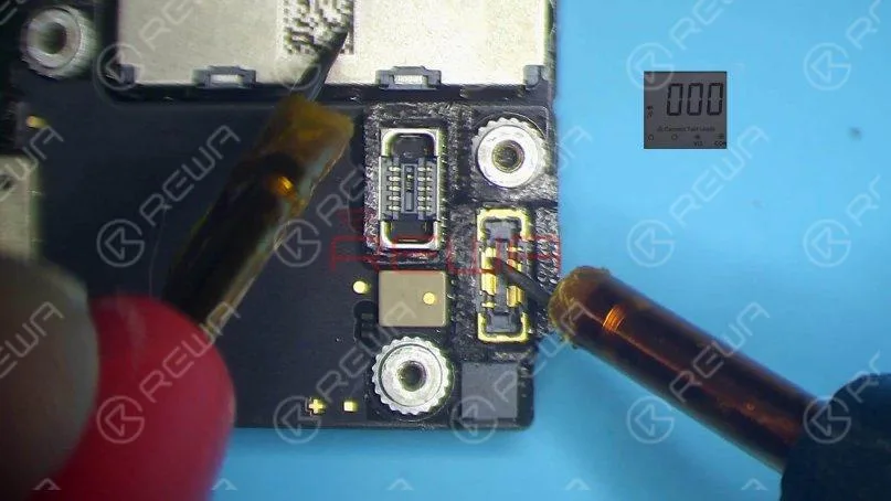
    Run diode mode measurement of pin 1 on the J7010 of the battery connector. The diode value is 0 which indicates that the main power supply circuit is shorted to the ground.

    Run diode mode measurement of pin 1 on the J7010 of the battery connector. The diode value is 0 which indicates that the main power supply circuit is shorted to the ground.

    Since the circuit simultaneously supplies power for the logic board and signal board, we need to separate the motherboard to locate the fault.

    Schritt 3: Trennung der Hauptplatine

    Remove foam on the motherboard. Then heat the back of the motherboard with Heißluftpistole at 240℃ to remove the shielding paper.
    Remove foam on the motherboard. Then heat the back of the motherboard with Hot Air Gun at 240℃ to remove the shielding paper.

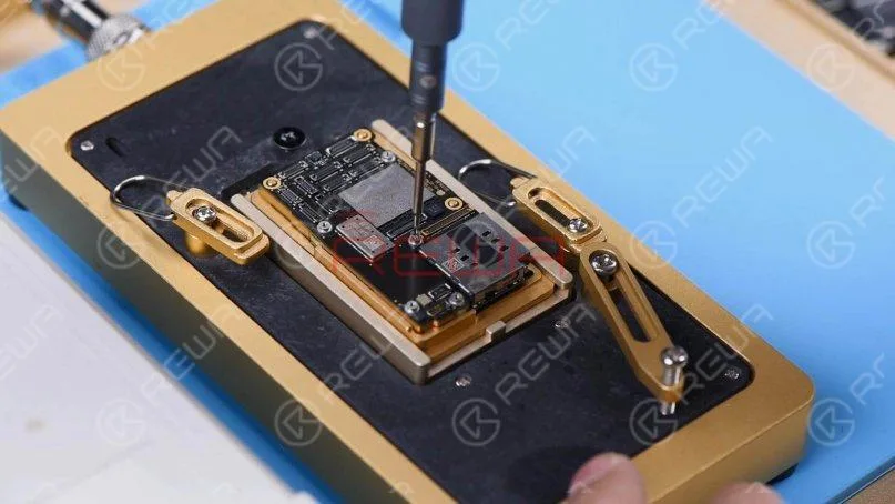
    Put the motherboard on the Heizungsplattform. To make it easier to remove the logic board after separation, drive a screw on the logic board.
    Put the motherboard on the Heating Platform. To make it easier to remove the logic board after separation, drive a screw on the logic board.

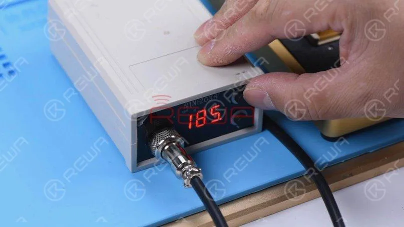
    Set the temperature of the Heating Platform to 185℃.

    Set the temperature of the Heating Platform to 185℃.

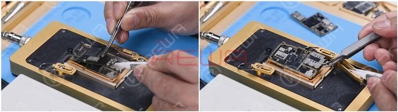
    Clamp the screw to remove the logic board when the temperature has risen to 185℃. Lastly, remove the signal board.
    Clamp the screw to remove the logic board when the temperature has risen to 185℃. Lastly, remove the signal board.

    Schritt 4: Messung im Diodenmodus erneut durchführen

    Run diode mode measurement of pin 286 on the signal board. The diode value is 0. It suggests that the main power supply of the signal board is shorted to the ground.

    Run diode mode measurement of pin 286 on the signal board. The diode value is 0. It suggests that the main power supply of the signal board is shorted to the ground.

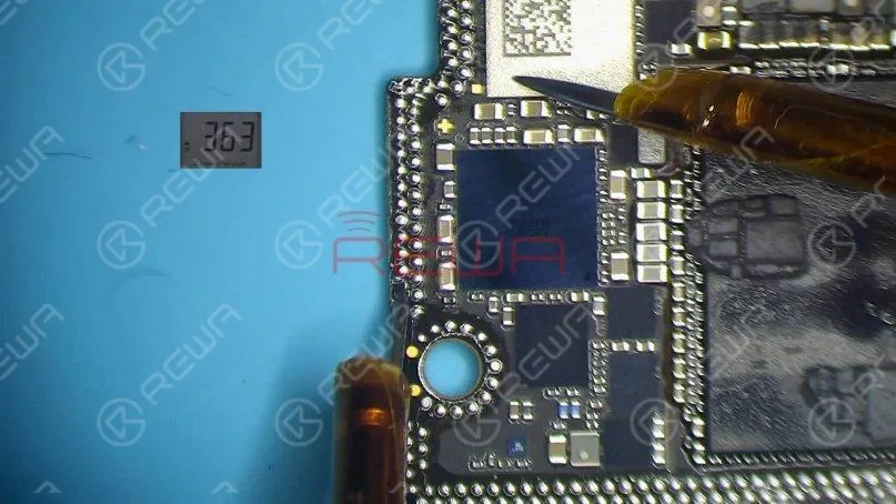
    Measure pin 286 on the logic board. The diode value is 363 which means the logic board is normal.

    Measure pin 286 on the logic board. The diode value is 363 which means the logic board is normal.

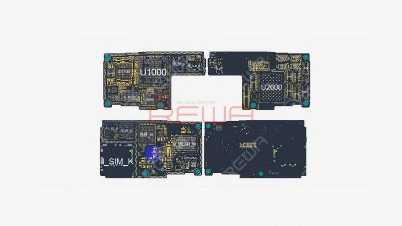
    Open the Bitmap. We can see there are many associated components on the main power supply circuit.

    Open the bitmap. We can see there are many associated components on the main power supply circuit.

    Step 5: Rosin detecting to locate the fault

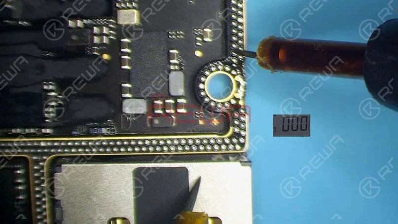
    Next, we need to locate the faulty component with rosin detecting.Remove thermal grease with a Sculpture Knife. Then dip rosin with Lötkolben at 365℃ and smoke rosin on the signal board.

    Next, we need to locate the faulty component with rosin detecting.Remove thermal grease with a Sculpture Knife. Then dip rosin with Soldering Iron at 365℃ and smoke rosin on the signal board.

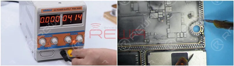
    Set the direct current supply to 4.1V. Connect the positive and negative anode of the direct current supply with multimeter probes. Connect the black probe to the ground and connect the red probe to pin 286 on the signal board. We can see rosin on C1200_K has melted. It indicates that the capacitor is damaged.

    Set the direct current supply to 4.1V. Connect the positive and negative anode of the direct current supply with multimeter probes. Connect the black probe to the ground and connect the red probe to pin 286 on the signal board. We can see rosin on C1200_K has melted. It indicates that the capacitor is damaged.

    Step 6: Eliminate the fault and restore the motherboard

    Then we heat the damaged capacitor with Hot Air Gun at 350℃ and remove it with tweezers.

    Then we heat the damaged capacitor with Hot Air Gun at 350℃ and remove it with tweezers.

    Clean rosin on the signal board with PCB Cleaner. Run a second diode mode measurement. The diode value returns to a normal value of 327.

    Clean rosin on the signal board with PCB Cleaner. Run a second diode mode measurement. The diode value returns to a normal value of 327.

    Smear rosin with Soldering Iron and solder wick at 365℃ to remove tin on the bonding pad. Clean the signal board with PCB Cleaner.

    Smear rosin with Soldering Iron and solder wick at 365℃ to remove tin on the bonding pad. Clean the signal board with PCB Cleaner.

    Remove tin and clean the logic board with the same method.Attach the signal board to the Reballing-Plattform and put the Reballing Stencil in position. To prevent the solder paste from flowing into the motherboard crevices, insert a metal plate. Apply a layer of low-temperature Lötpaste. 

    Remove tin and clean the logic board with the same method.Attach the signal board to the Reballing Platform and put the Reballing Stencil in position. To prevent the solder paste from flowing into the motherboard crevices, insert a metal plate. Apply a layer of low-temperature Solder Paste.

    Remove the Reballing Stencil and put the signal board on the Heating Platform at 185℃ to heat. After the solder balls are formed, turn the power off and cool the motherboard for 5 minutes.

    Remove the Reballing Stencil and put the signal board on the Heating Platform at 185℃ to heat. After the solder balls are formed, turn the power off and cool the motherboard for 5 minutes.

    Einige anwenden Paste Flussmittel and align the logic board with the signal board. Keep heating on the Heating Platform at 185℃. When the temperature reaches 185℃, keep heating for 1 minute.This step is to ensure that the logic board and the signal board fit closely.

    Apply some Paste Flux and align the logic board with the signal board. Keep heating on the Heating Platform at 185℃. When the temperature reaches 185℃, keep heating for 1 minute.This step is to ensure that the logic board and the signal board fit closely.Step 7: Test and assemble

    Connect the motherboard with the Power Cable and short to the ground of the J7700 pin 12. The boot current becomes normal.

    Connect the motherboard with the Power Cable and short to the ground of the J7700 pin 12. The boot current becomes normal.

    Put the motherboard on the phone. Connect the flex cables, screen, and battery. Because the battery is dead, plug the charging cable and the phone turns on normally.

    Put the motherboard on the phone. Connect the flex cables, screen, and battery. Because the battery is dead, plug the charging cable and the phone turns on normally.

    Schlussfolgerung:

    iPhone 11 Pro won’t turn on with a large current. We found that the main power supply was shorted to the ground through measuring the battery connector. The fault was found to be on the signal board after separation. Rosin detecting showed us that C1200_K was damaged. After removing C1200_K, the fault was cleared.