Schlagwort: iphone 11 pro

  • iPhone 11 Pro lässt sich nicht einschalten - Professionelle Reparaturanleitung

    iPhone 11 Pro lässt sich nicht einschalten - Professionelle Reparaturanleitung

    Hello everyone! Our course today is about repairing an iPhone 11 Pro that won’t turn on.

    Press the power button. The phone won’t turn on.
    How to Fix iPhone 11 Won't Turn On with Large Current

    Disassemble and Test

    Then we disassemble the phone and test.

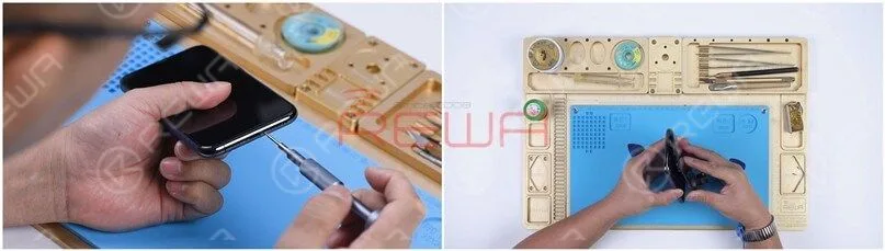
    Remove the two pentalobe screws at the bottom edge.

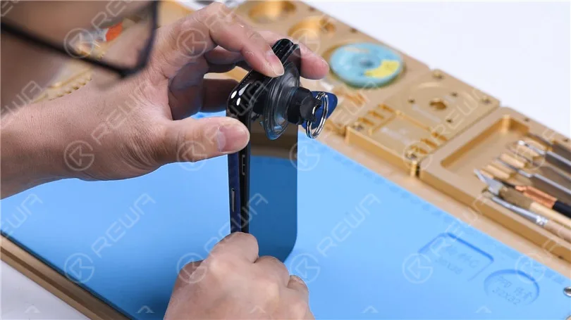
    Pull up on the small nub on the Suction Cup to lift the screen.

    Insert a Pry Piece when there is a gap and slide it along the gap.
    How to Fix iPhone 11 Won't Turn On with Large Current

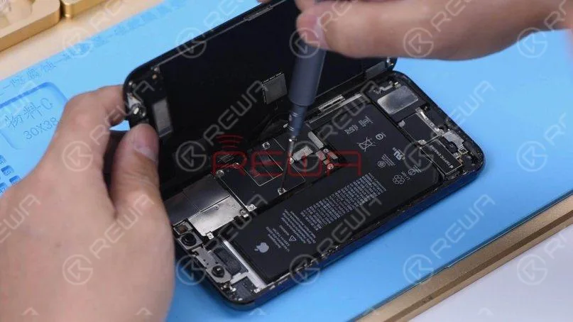
    After the screen is lifted, take the shielding covers off.

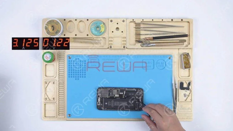
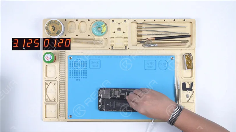
    Disconnect the battery and remove the screen. Connect the motherboard with the Power Cable.

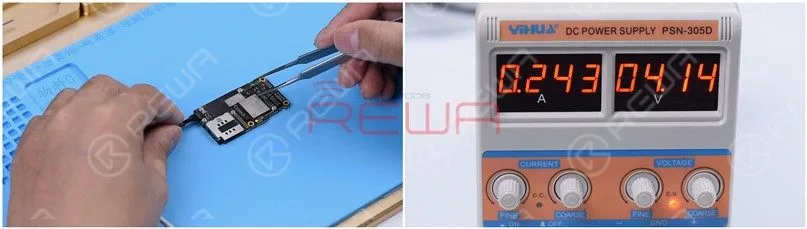
    The ammeter shows a large current of 3.1A.
    How to Fix iPhone 11 Won't Turn On with Large Current

    Disconnect the flex cables. Remove the SIM card tray.

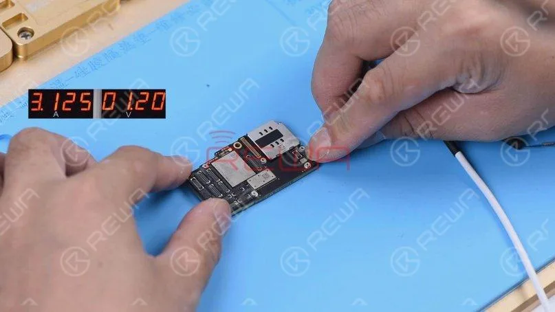
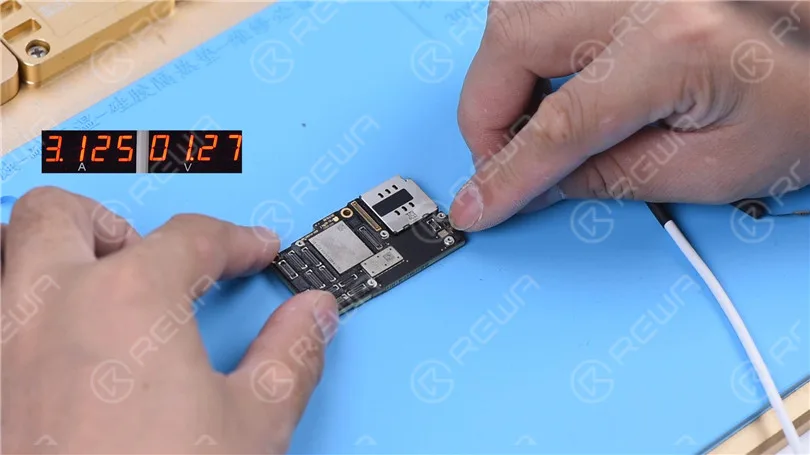
    Detach the motherboard. Connect the motherboard with the Power Cable again.

    The ammeter still shows a large current of 3.1A.

    It indicates that the large current has nothing to do with other flex cables.

    The fault is on the motherboard.
    How to Fix iPhone 11 Won't Turn On with Large Current

    Messung im Diodenmodus

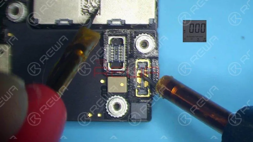
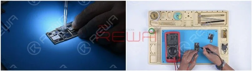
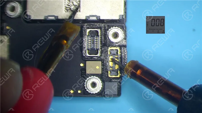
    Run diode mode measurement of pin 1 on the J7010 of the battery connector.

    The diode value is 0. It indicates that the main power supply circuit is shorted to the ground.

    Since the circuit simultaneously supplies power for the logic board and signal board, we need to separate the motherboard to locate the fault.
    How to Fix iPhone 11 Won't Turn On with Large Current

    Motherboard-Trennung

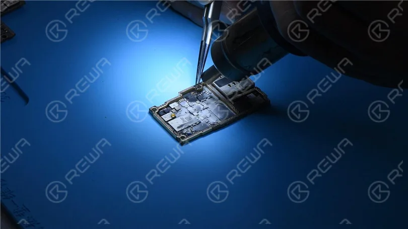
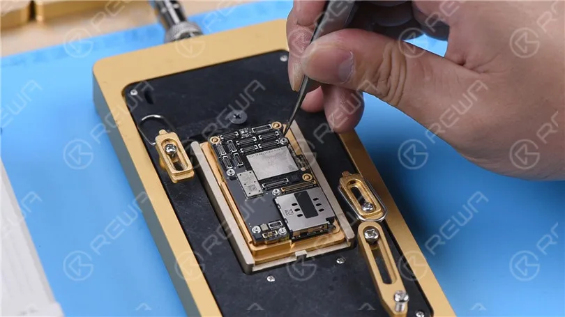
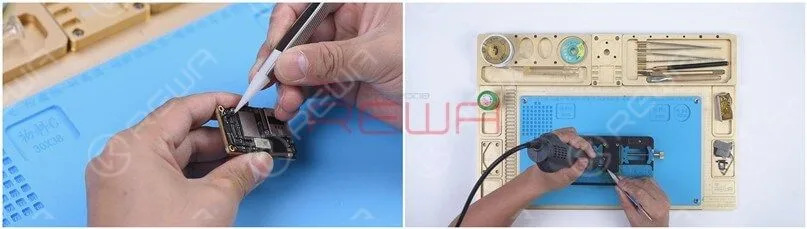
    Remove foam on the motherboard.

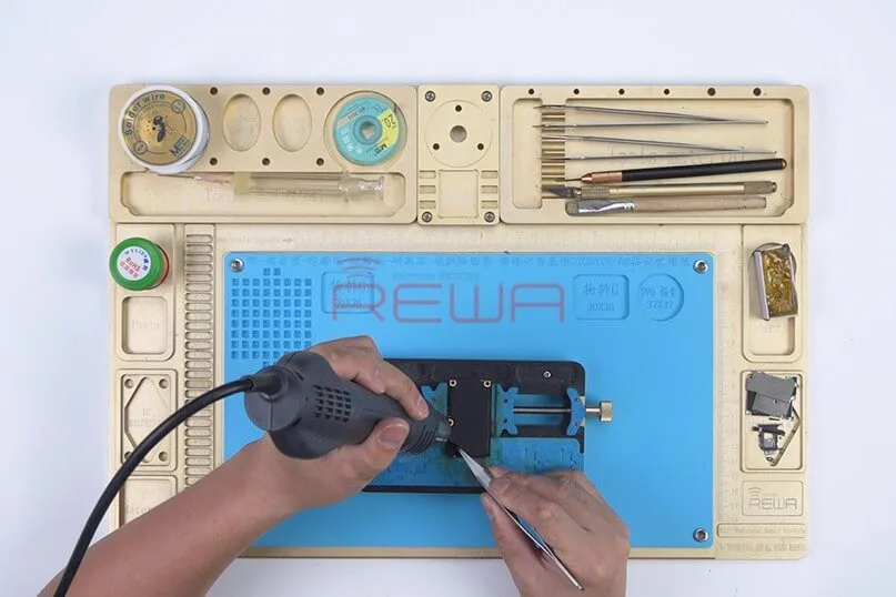
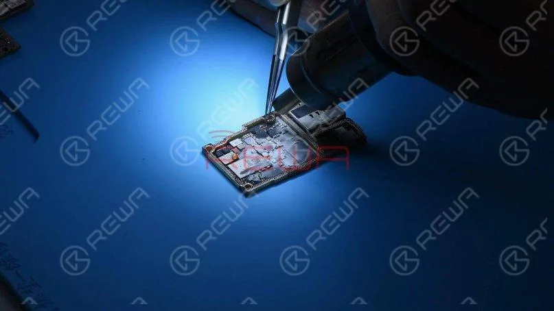
    Heat the back of the motherboard with Hot Air Gun at 240 degrees celsius.

    Remove the shielding paper.

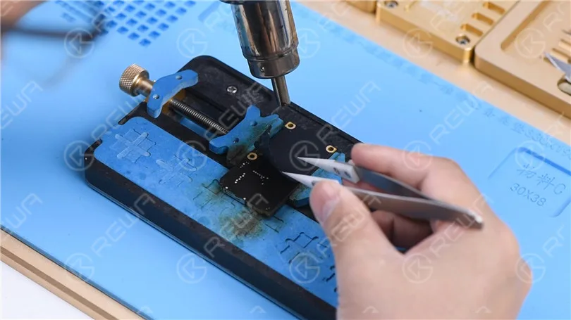
    Put the motherboard on the Heizungsplattform.

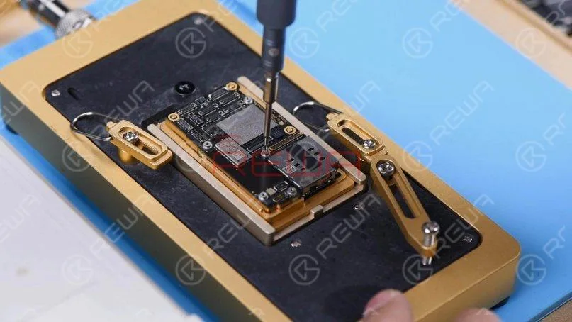
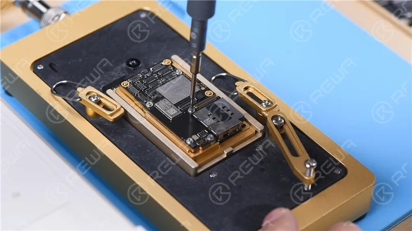
    Um das Entfernen der Logikkarte nach der Trennung zu erleichtern, drehen Sie eine Schraube auf die Logikkarte.

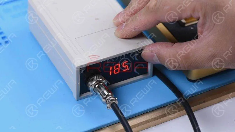
    Set the temperature of the Heating Platform to 185 degrees celsius.

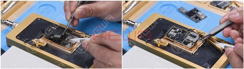
    Clamp the screw to remove the logic board when the temperature has risen to 185 degrees celsius. Remove the signal board.
    How to Fix iPhone 11 Won't Turn On with Large Current
    How to Fix iPhone 11 Won't Turn On with Large Current

    Messung im Diodenmodus

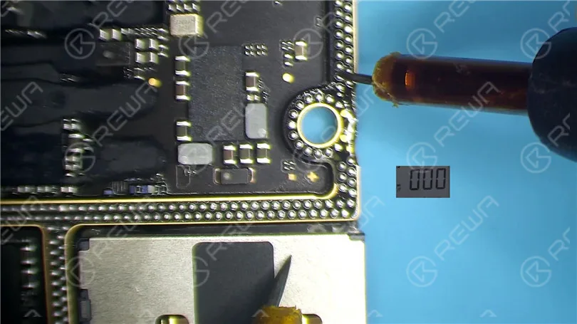
    Run diode mode measurement of pin 286 on the signal board. The diode value is 0.

    It indicates that the main power supply of the signal board is shorted to the ground.

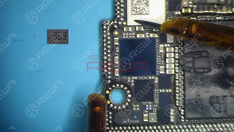
    Measure pin 286 on the logic board.

    The diode value is 363 which means the logic board is normal.
    How to Fix iPhone 11 Won't Turn On with Large Current
    How to Fix iPhone 11 Won't Turn On with Large Current

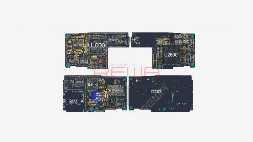
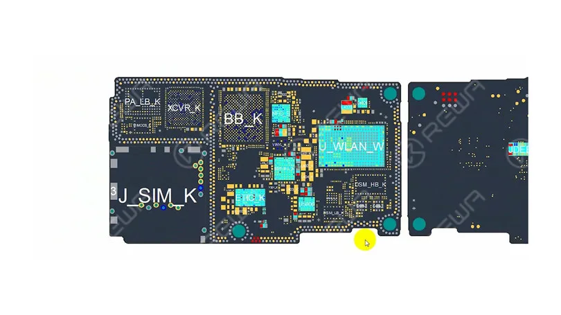
    Open the bitmap. We can see there are many associated components on the main power supply circuit.

    How to Fix iPhone 11 Won't Turn On with Large Current

    Rosin Detecting

    Next, we need to locate the faulty component with rosin detecting.

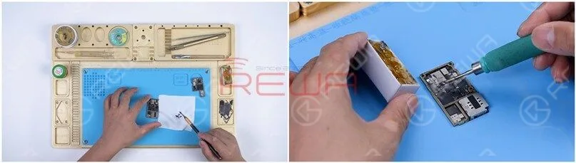
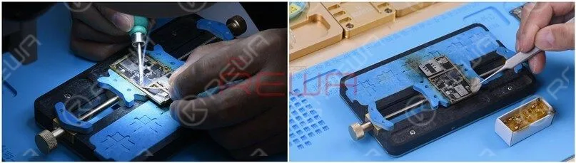
    Remove thermal grease with a Sculpture Knife.

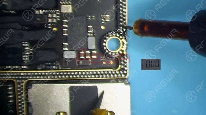
    Dip rosin with Soldering Iron at 365 degrees celsius.

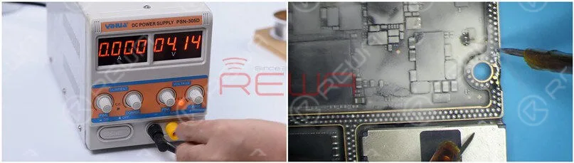
    Smoke rosin on the signal board. Set the direct current supply to 4.1V.

    Connect the positive and negative anode of the direct current supply with multimeter probes.

    Connect the black probe to the ground.

    Connect the red probe to pin 286 on the signal board.

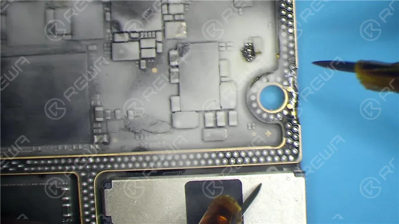
    We can see rosin on C1200 K has melted. It indicates that the capacitor is damaged.

    How to Fix iPhone 11 Won't Turn On with Large Current
    How to Fix iPhone 11 Won't Turn On with Large Current

    Then we heat it with Hot Air Gun at 350 degrees celsius. Remove the capacitor with tweezers.

    How to Fix iPhone 11 Won't Turn On with Large Current

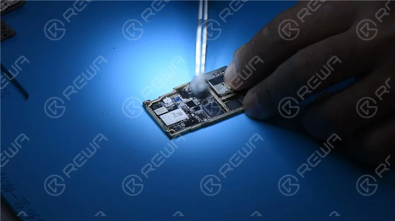
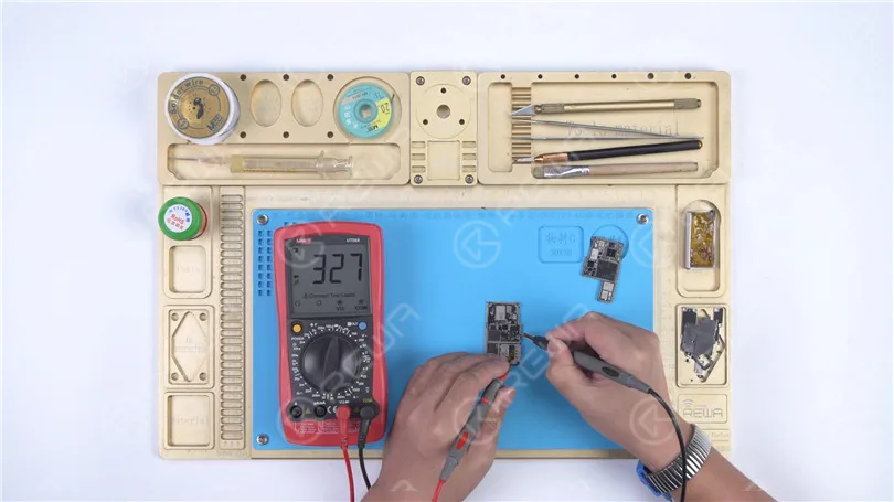
    Clean rosin on the signal board with PCB Cleaner. Run a second diode mode measurement. The diode value returns to a normal value of 327.

    How to Fix iPhone 11 Won't Turn On with Large Current
    How to Fix iPhone 11 Won't Turn On with Large Current

    Motherboard Rekombination

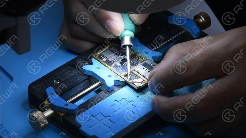
    Smear rosin with Soldering Iron and solder wick at 365 degrees celsius to remove tin on the bonding pad.

    Clean the signal board with PCB Cleaner. Remove tin and clean the logic board with the same method.

    How to Fix iPhone 11 Won't Turn On with Large Current

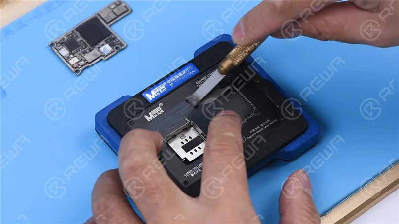
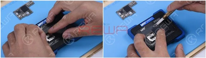
    Attach the signal board to the Reballing Platform.

    Put the Reballing Stencil in position. To prevent the solder paste from flowing into the motherboard crevices, insert a metal plate.

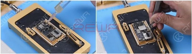
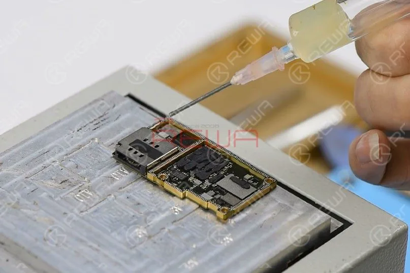
    Apply a layer of low-temperature Solder Paste.

    Remove the Reballing Stencil.

    How to Fix iPhone 11 Won't Turn On with Large Current

    Put the signal board on the Heating Platform at 185 degrees celsius to heat.

    After the solder balls are formed, turn the power off and cool the motherboard for 5 minutes.

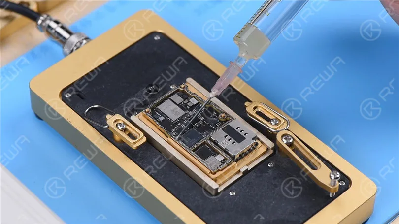
    Apply some Paste Flux.

    Richten Sie die Logikplatine an der Signalplatine aus.

    Keep heating on the Heating Platform at 185 degrees celsius.

    When the temperature reaches 185 degrees celsius, keep heating for 1 minute.

    This step is to ensure that the logic board and the signal board fit closely.

    How to Fix iPhone 11 Won't Turn On with Large Current
    How to Fix iPhone 11 Won't Turn On with Large Current
    How to Fix iPhone 11 Won't Turn On with Large Current

    Prüfung

    Connect the motherboard with the Power Cable.

    Short to the ground of the J7700 pin 12. The boot current becomes normal.

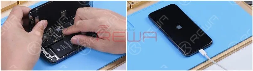
    Put the motherboard on the phone.

    Connect the flex cables. Connect the screen and battery.

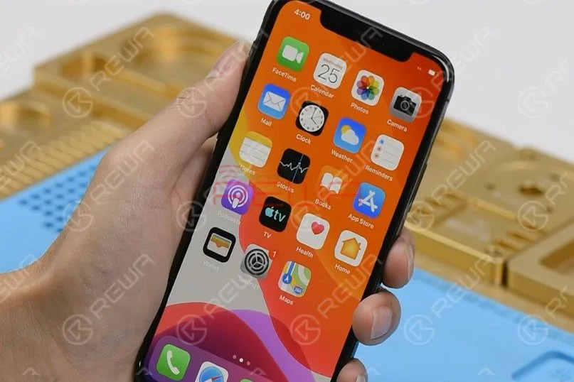
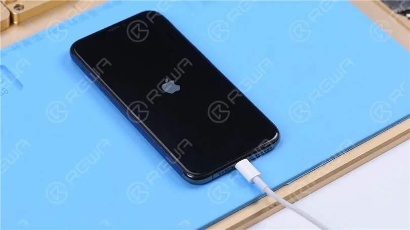
    Because the battery is dead. Plug the charging cable and the phone turns on normally.

    How to Fix iPhone 11 Won't Turn On with Large Current
    How to Fix iPhone 11 Won't Turn On with Large Current
  • How to Fix an iPhone 11 Pro Won’t Turn On

    How to Fix an iPhone 11 Pro Won’t Turn On

    Having trouble with your iPhone 11 Pro refusing to turn on? Don’t worry, we’ve got your back! In this comprehensive guide, we’ll walk you through some practical and effective solutions to fix this frustrating issue.

    Step 1: Disassemble and test

    Remove the two pentalobe screws at the bottom edge and lift the screen.
    Remove the two pentalobe screws at the bottom edge and lift the screen.

    After the screen is lifted, take the shielding covers off, disconnect the battery, and remove the screen.
    After the screen is lifted, take the shielding covers off, disconnect the battery, and remove the screen.

    Connect the motherboard with the Power Cable. The ammeter shows a large current of 3.1A.
    Connect the motherboard with the Power Cable. The ammeter shows a large current of 3.1A.

    Detach the motherboard and connect the motherboard with the Power Cable again. The ammeter still shows a large current of 3.1A.
    Detach the motherboard and connect the motherboard with the Power Cable again. The ammeter still shows a large current of 3.1A.

    It indicates that the large current has nothing to do with other flex cables. The fault is on the motherboard.

    Schritt 2: Messung im Diodenmodus durchführen

    Run diode mode measurement of pin 1 on the J7010 of the battery connector. The diode value is 0 which indicates that the main power supply circuit is shorted to the ground.

    Run diode mode measurement of pin 1 on the J7010 of the battery connector. The diode value is 0 which indicates that the main power supply circuit is shorted to the ground.

    Since the circuit simultaneously supplies power for the logic board and signal board, we need to separate the motherboard to locate the fault.

    Schritt 3: Trennung der Hauptplatine

    Remove foam on the motherboard. Then heat the back of the motherboard with Heißluftpistole at 240℃ to remove the shielding paper.
    Remove foam on the motherboard. Then heat the back of the motherboard with Hot Air Gun at 240℃ to remove the shielding paper.

    Put the motherboard on the Heizungsplattform. To make it easier to remove the logic board after separation, drive a screw on the logic board.
    Put the motherboard on the Heating Platform. To make it easier to remove the logic board after separation, drive a screw on the logic board.

    Set the temperature of the Heating Platform to 185℃.

    Set the temperature of the Heating Platform to 185℃.

    Clamp the screw to remove the logic board when the temperature has risen to 185℃. Lastly, remove the signal board.
    Clamp the screw to remove the logic board when the temperature has risen to 185℃. Lastly, remove the signal board.

    Schritt 4: Messung im Diodenmodus erneut durchführen

    Run diode mode measurement of pin 286 on the signal board. The diode value is 0. It suggests that the main power supply of the signal board is shorted to the ground.

    Run diode mode measurement of pin 286 on the signal board. The diode value is 0. It suggests that the main power supply of the signal board is shorted to the ground.

    Measure pin 286 on the logic board. The diode value is 363 which means the logic board is normal.
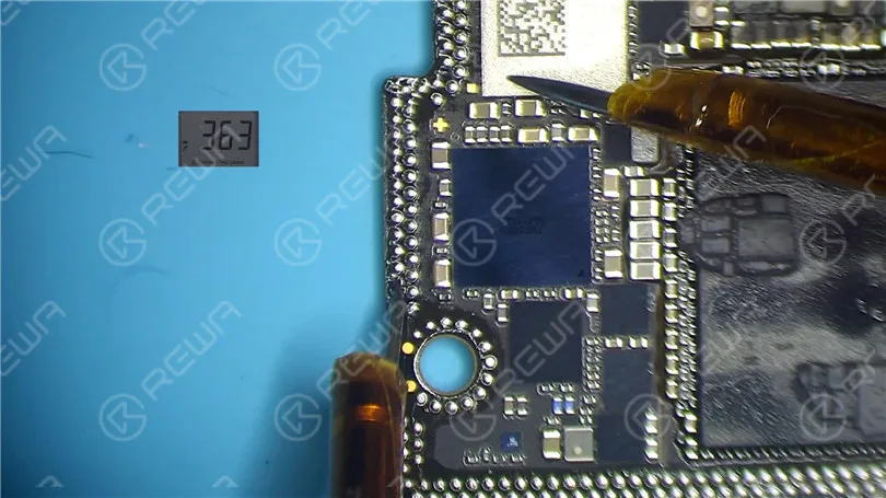
    Measure pin 286 on the logic board. The diode value is 363 which means the logic board is normal.

    Open the Bitmap. We can see there are many associated components on the main power supply circuit.

    Open the bitmap. We can see there are many associated components on the main power supply circuit.
    Step 5: Rosin detecting to locate the fault

    Next, we need to locate the faulty component with rosin detecting.Remove thermal grease with a Sculpture Knife. Then dip rosin with Lötkolben at 365℃ and smoke rosin on the signal board.

    Next, we need to locate the faulty component with rosin detecting.Remove thermal grease with a Sculpture Knife. Then dip rosin with Soldering Iron at 365℃ and smoke rosin on the signal board.

    Set the direct current supply to 4.1V. Connect the positive and negative anode of the direct current supply with multimeter probes. Connect the black probe to the ground and connect the red probe to pin 286 on the signal board. We can see rosin on C1200_K has melted. It indicates that the capacitor is damaged.
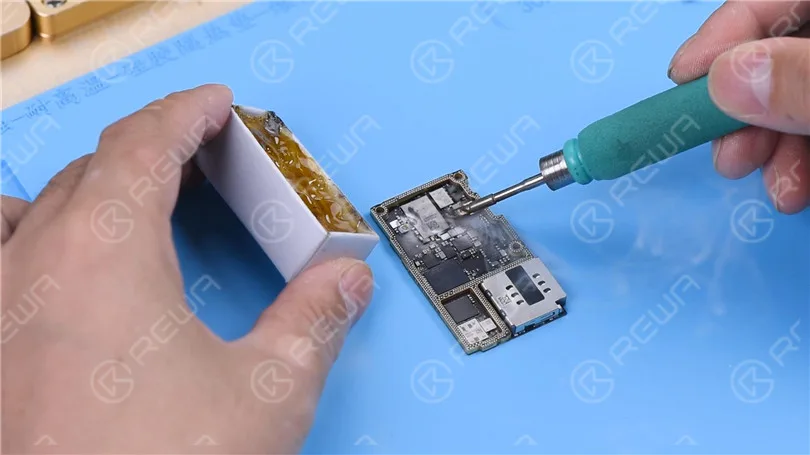
    Set the direct current supply to 4.1V. Connect the positive and negative anode of the direct current supply with multimeter probes. Connect the black probe to the ground and connect the red probe to pin 286 on the signal board. We can see rosin on C1200_K has melted. It indicates that the capacitor is damaged.
    Step 6: Eliminate the fault and restore the motherboard

    Then we heat the damaged capacitor with Hot Air Gun at 350℃ and remove it with tweezers.

    Then we heat the damaged capacitor with Hot Air Gun at 350℃ and remove it with tweezers.

    Clean rosin on the signal board with PCB Cleaner. Run a second diode mode measurement. The diode value returns to a normal value of 327.
    Clean rosin on the signal board with PCB Cleaner. Run a second diode mode measurement. The diode value returns to a normal value of 327.

    Smear rosin with Soldering Iron and solder wick at 365℃ to remove tin on the bonding pad. Clean the signal board with PCB Cleaner.

    Smear rosin with Soldering Iron and solder wick at 365℃ to remove tin on the bonding pad. Clean the signal board with PCB Cleaner.

    Remove tin and clean the logic board with the same method.Attach the signal board to the Reballing-Plattform and put the Reballing Stencil in position. To prevent the solder paste from flowing into the motherboard crevices, insert a metal plate. Apply a layer of low-temperature Lötpaste. 

    Remove tin and clean the logic board with the same method.Attach the signal board to the Reballing Platform and put the Reballing Stencil in position. To prevent the solder paste from flowing into the motherboard crevices, insert a metal plate. Apply a layer of low-temperature Solder Paste.

    Remove the Reballing Stencil and put the signal board on the Heating Platform at 185℃ to heat. After the solder balls are formed, turn the power off and cool the motherboard for 5 minutes.

    Remove the Reballing Stencil and put the signal board on the Heating Platform at 185℃ to heat. After the solder balls are formed, turn the power off and cool the motherboard for 5 minutes.

    Einige anwenden Paste Flussmittel and align the logic board with the signal board. Keep heating on the Heating Platform at 185℃. When the temperature reaches 185℃, keep heating for 1 minute.This step is to ensure that the logic board and the signal board fit closely.
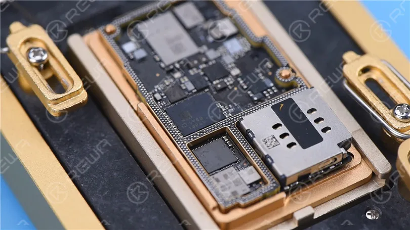
    Apply some Paste Flux and align the logic board with the signal board. Keep heating on the Heating Platform at 185℃. When the temperature reaches 185℃, keep heating for 1 minute.This step is to ensure that the logic board and the signal board fit closely.Step 7: Test and assemble

    Connect the motherboard with the Power Cable and short to the ground of the J7700 pin 12. The boot current becomes normal.

    Connect the motherboard with the Power Cable and short to the ground of the J7700 pin 12. The boot current becomes normal.

    Put the motherboard on the phone. Connect the flex cables, screen, and battery. Because the battery is dead, plug the charging cable and the phone turns on normally.
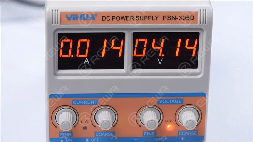
    Put the motherboard on the phone. Connect the flex cables, screen, and battery. Because the battery is dead, plug the charging cable and the phone turns on normally.
    Schlussfolgerung:

    iPhone 11 Pro won’t turn on with a large current. We found that the main power supply was shorted to the ground through measuring the battery connector. The fault was found to be on the signal board after separation. Rosin detecting showed us that C1200_K was damaged. After removing C1200_K, the fault was cleared.

  • iPhone 11 Pro Motherboard Separation

    iPhone 11 Pro Motherboard Separation

    As we all know, iPhone new series have undergone considerable changes on both inside and outside.

    Especially on the motherboard.

    How will these changes affect the repair industry?

    Will it make third-party repair harder or easier?

    Follow our iPhone 11 Pro motherboard separation & recombination blog today and find the answer by yourself.

    iPhone 11 Pro Motherboard Separation

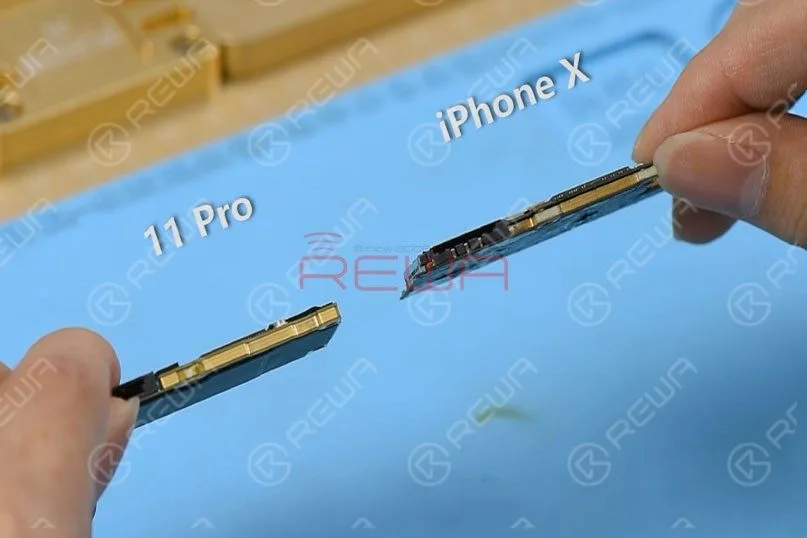
    Compared with iPhone X series, iPhone 11 Pro’s motherboard is smaller with a much denser component array.

    It is also thicker.

    There are layers of graphite thermal transfer material on the backside.

    It can dissipate heat generated from the motherboard efficiently.
    Compared with iPhone X series, iPhone 11 Pro’s motherboard is smaller with a much denser component array. It is also thicker. There are layers of graphite thermal transfer material on the backside. It can dissipate heat generated from the motherboard efficiently.

    Schritt 1

    Remove the graphite thermal transfer material with tweezers first.

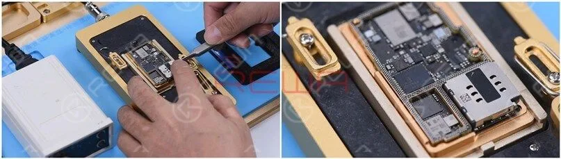
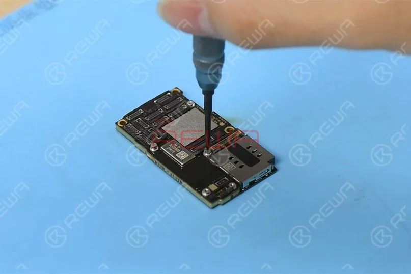
    To recombine the two layers without reballing after separation, let’s fit two screws into the screw holes reserved on the motherboard.

    Remove the graphite thermal transfer material with tweezers first. To recombine the two layers without reballing after separation, let’s fit two screws into the screw holes reserved on the motherboard.

    Schritt 2

    Set temperature of the heating platform at 170℃.

    With temperature of the platform reaching 170℃, place the motherboard on the platform to heat for 3 minutes.

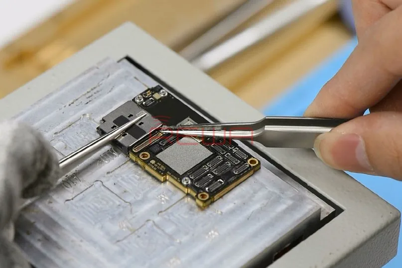
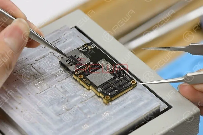
    Press the SIM card reader with the tweezers and push the upper layer with another tweezers slightly.
    Set temperature of the heating platform at 170℃. With temperature of the platform reaching 170℃, place the motherboard on the platform to heat for 3 minutes. Press the SIM card reader with the tweezers and push the upper layer with another tweezers slightly.

    Schritt 3

    With solder balls on the third space PCB starting to melt, clamp the screws fitted into the screw holes with tweezers and pick up the upper layer with tweezers vertically.

    Tips: do not shake the tweezers when picking up the upper layer.

    The third space PCB might be stuck in bridging issues and the recombination work would also be affected.

    Fahren Sie mit der Aufnahme der unteren Schicht fort.

    iPhone 11 Pro Motherboard Structure

    Now let’s start with the structure of the motherboard.

    The Upper Layer

    iPhone 11 Pro Motherboard Structure

    A.Thermal Compound

    CPU and areas around CPU are covered with a large amount of thermal compound to dissipate heat generated from A13 CPU.

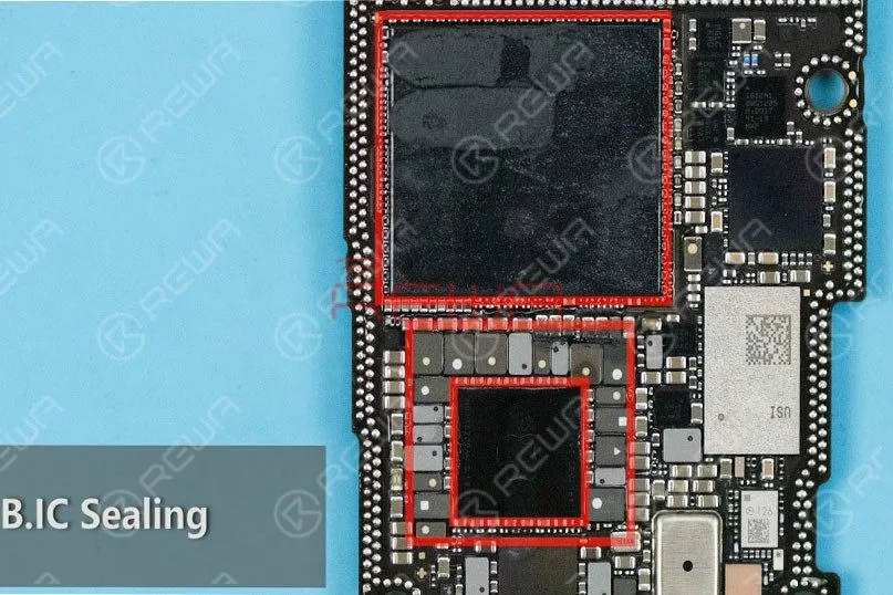
    B.IC Sealing

    CPU, PMU, and inductors around PMU are sealed with adhesive adding to the difficulty of repairs to some extent.

    C.Dense Component Array Around PMU

    Professional handwork is required when soldering/desoldering PMU.

    D.USB-IC

    Unlike iPhone X series, the USB IC of iPhone 11 Pro hasn’t been sealed with adhesive, and it is far from CPU.

    Therefore, the difficulty of USB IC relevant repairs is relatively reduced

    Unlike iPhone X series, the A13 CPU of iPhone 11 Pro is not located right on the backside of the NAND flash chip.

    This can reduce the bridging possibility of CPU when soldering/desoldering the NAND flash chip.

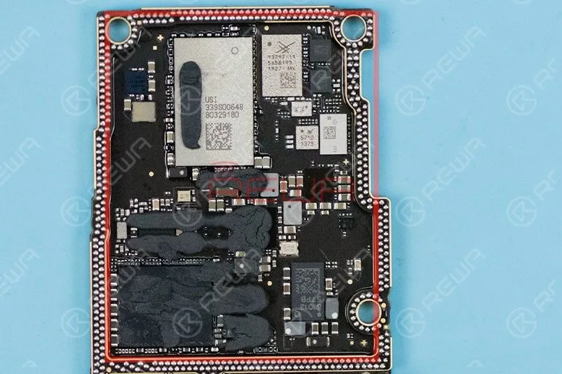
    The Lower Layer

    The Lower Layer

    A. Different from iPhone X series, the lower layer of iPhone 11 Pro has a dispersive component array. Therefore, the difficulty of signal relevant repairs is also reduced.

    B. Unlike iPhone X series, the SIM card reader of iPhone 11 Pro is independent from other components. We don’t have to remove the SIM card reader when working on signal relevant repairs.

    iPhone 11 Pro Motherboard Recombination Without Reballing

    Set temperature of the heating platform at 170℃.

    Wenn die Temperatur der Plattform 170℃ erreicht hat, legen Sie die untere Schicht auf die Plattform und erhitzen sie 10 Sekunden lang.

    Tragen Sie gleichmäßig etwas Paste Flux auf die dritte Lücke der Leiterplatte auf.

    Get the upper layer in position and heat for about 5 minutes.
    Set temperature of the heating platform at 170℃. With temperature of the platform reaching 170℃, place the lower layer on the platform to heat for 10 seconds. Apply some Paste Flux to the third space PCB evenly. Get the upper layer in position and heat for about 5 minutes.

    Then, press the SIM card reader with the tweezers and push the upper layer with another tweezers slightly.

    If the upper layer returns to the previous position automatically, then the soldering process is completed.

    Test

    Now we can assemble the phone and test.

    Test    Now we can assemble the phone and test.

    Get the motherboard and display assembly installed and get the battery connected.

    Drücken Sie die Ein-/Aus-Taste, um das Telefon einzuschalten.

    Das Telefon schaltet sich normal ein.

    Funktionstest durchführen. Alles läuft gut.

    Zusammenfassung

    The separation&recombination of the motherboard of iPhone 11 Pro shows that the motherboard is smaller and more squared.

    Compared with the iPhone X series, it will not be easily damaged by external forces.

    The high integration of the motherboard also means that more professional handwork is required.

    Overall, the difficulty of iPhone 11 Pro motherboard repairs is reduced.

    Werkzeuge und Teile

    Sie können auch besuchen REWA Youtube Kanal to check our video of iPhone 11 Pro Motherboard Separation And Recombination.

  • iPhone 11 Pro Rückseite Glasreparatur

    iPhone 11 Pro Rückseite Glasreparatur

    Es ist das leistungsstärkste und fortschrittlichste iPhone, das Apple je gebaut hat, iPhone 11 Pro  ist aus rostfreiem Stahl in chirurgischer Qualität gefertigt, seine Rückseite besteht aus einem Stück Maschinenglas mit einer optischen PVD-Beschichtung, was die Reparatur zusätzlich erschwert.

    Darüber hinaus erhöht die Anordnung der rückwärtigen Kameras des iPhone 11 Pro auch die Schwierigkeit der Reparatur des hinteren Glases erheblich.

    REWA LAB hat verschiedene Lösungen ausprobiert (Erhitzen mit der Heißluftpistole, Trennen mit dem Dispergator/der Gefrierhilfe), aber wir waren nicht in der Lage, das Glas um die dreilinsige Kamera sicher und effizient zu entfernen.

    Überprüfen Sie unsere detaillierte Operation auf iPhone 11 Pro Rückseite Glas Reparatur und hoffen, dass wir Sie irgendwie erleuchten können.

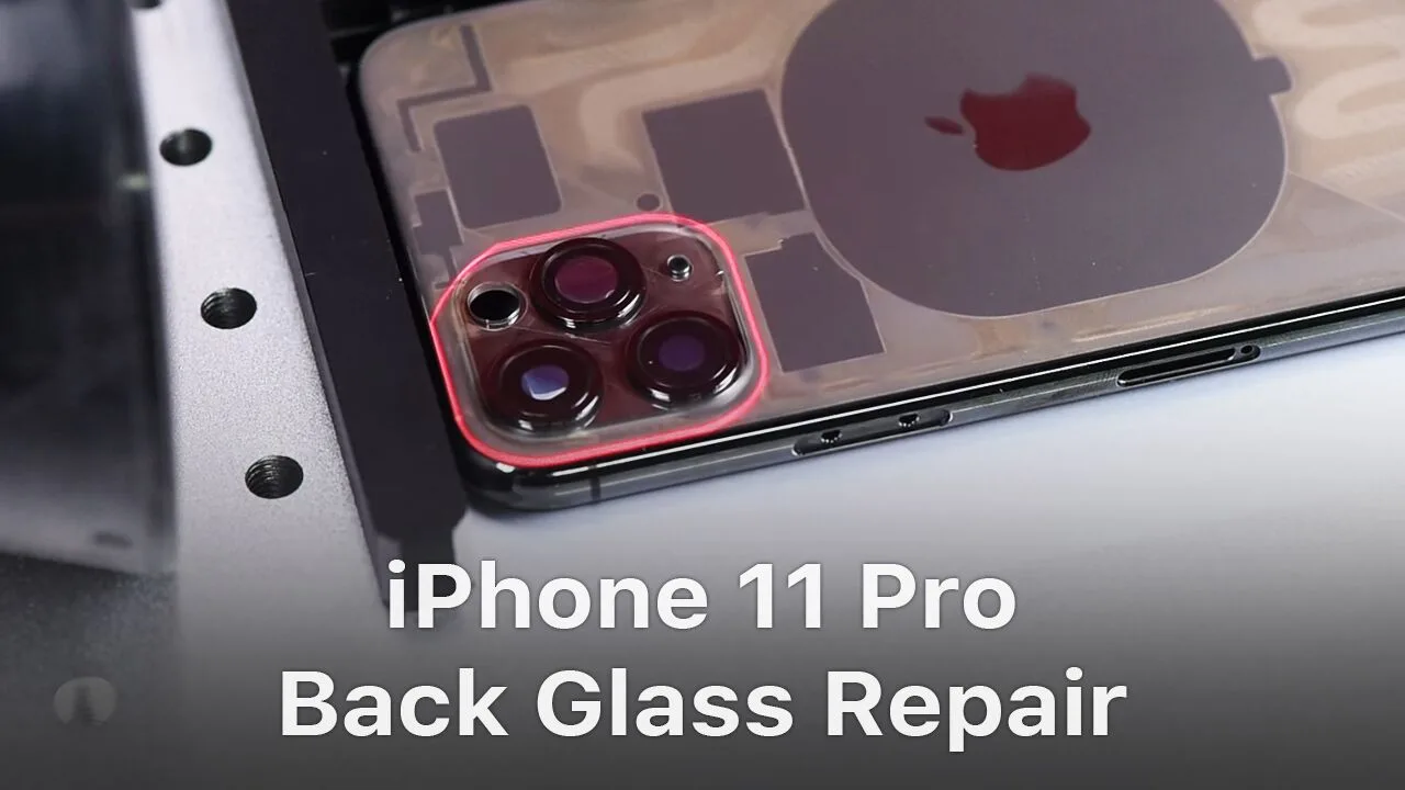
    Scannen des 11 Pro-Rückglases mit Laser

    Legen Sie zunächst das Glas der Rückseite des iPhone 11 Pro zum Fokussieren unter die Sonde.

    Legen Sie dann das hintere Glas des iPhone 11 Pro auf das Bedienfeld.

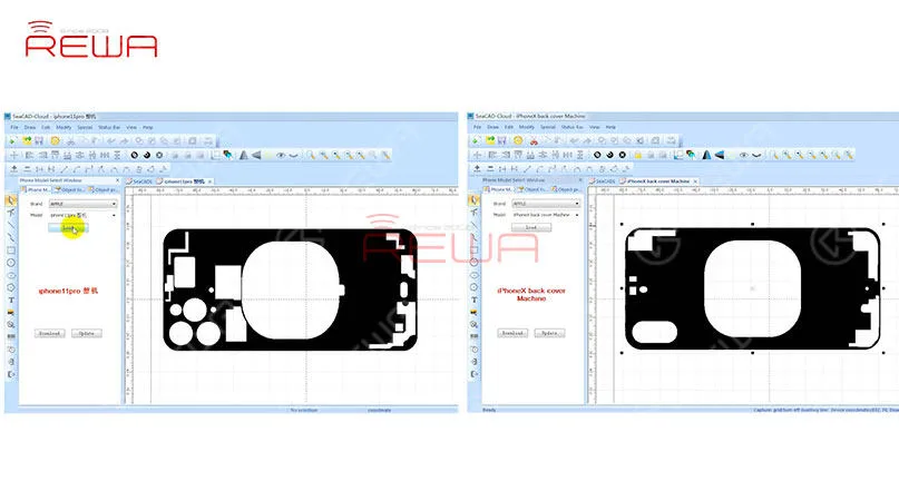
    Wählen Sie "iPhone 11 Pro" aus der Modellliste und klicken Sie auf "Laden", um die Zeichnung zu laden.

    Der schwarze Bereich auf der Zeichnung ist der Bereich, der gescannt werden soll, und der weiße Bereich ist der Bereich, der beibehalten werden soll.

    Tipps: Vergleichen Sie die beiden Zeichnungen und wir können sehen, dass anders als iPhone X, gibt es mehr Bereiche, die der Laser sollte weg von halten, wenn iPhone 11 Pro scannen.
    Legen Sie zunächst die Rückseite des iPhone 11 Pro zum Fokussieren unter die Sonde. Legen Sie dann das Rückglas des iPhone 11 Pro auf das Bedienfeld.   Wählen Sie "iPhone 11 Pro" aus der Modellliste und klicken Sie auf "Laden", um die Zeichnung zu laden.   Der schwarze Bereich auf der Zeichnung ist der Bereich, der gescannt werden soll, und der weiße Bereich ist der Bereich, der beibehalten werden soll.   Tipps: Wenn Sie die beiden Zeichnungen vergleichen, sehen Sie, dass es im Gegensatz zum iPhone X mehr Bereiche gibt, die der Laser beim Scannen des iPhone 11 Pro aussparen sollte.

    Nachdem Sie die Zeichnung des iPhone 11 Pro geladen haben, passen Sie den Laserlicht-Scanbereich auf der Glasrückseite an.

    Wenn Sie fertig sind, stellen Sie die Parameter ein und klicken Sie auf "Markieren", um die Rückscheibe mit dem Laserlicht zu scannen.

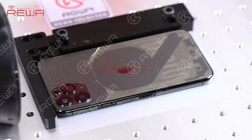
    Das hintere Glas wird nach der Laserabtastung transparent.
    Nachdem Sie die Zeichnung des iPhone 11 Pro geladen haben, stellen Sie den Laserlicht-Scanbereich auf der Rückseite des Glases ein. Sobald Sie fertig sind, stellen Sie die Parameter ein und klicken Sie auf "Markieren", um die Glasrückseite mit dem Laserlicht zu scannen. Das Rückglas wird nach dem Laserscan transparent.

    Scannen des Glases um die Dreilinsenkamera mit Laser

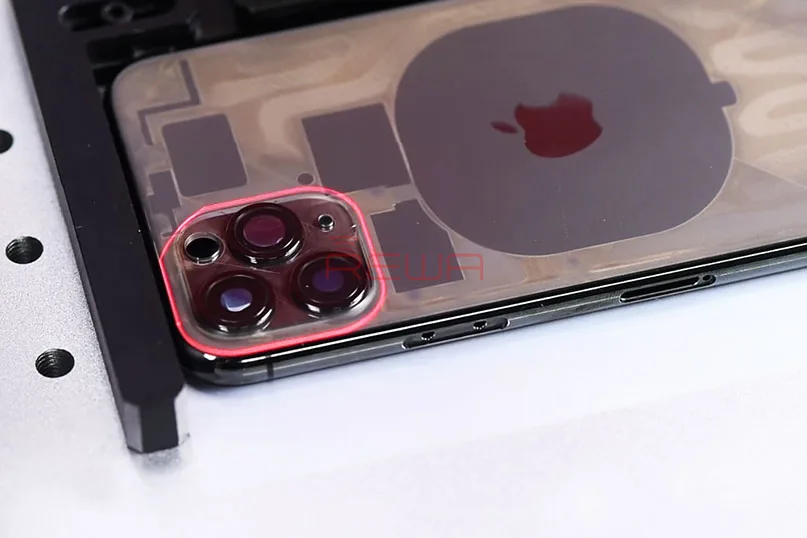
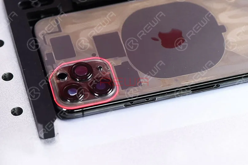
    Wie Sie sehen können, ist das Glas um die Kamera mit den drei Linsen relativ dick.

    Die Laserlichtabtastung hat in diesem Gebiet nicht gut funktioniert.

    Nach mehreren Versuchen und Experimenten ist es dem REWA LAB gelungen, eine Spezialzeichnung für den Bereich der dreilinsigen Kamera zu erstellen.

    Scannen Sie den Bereich der Dreilinsenkamera mit Hilfe der Zeichnung erneut mit dem Laser.

    Auch das Glas um die Dreilinsenkamera wird nach dem zweiten Laserscan transparent.
    Scannen Sie den Bereich der Triple-Lens-Kamera mit Hilfe der Zeichnung erneut mit dem Laser. Auch das Glas um die Triple-Lens-Kamera wird nach dem zweiten Laserscan transparent.

    Trennen Sie das hintere Glas vom mittleren Rahmen 

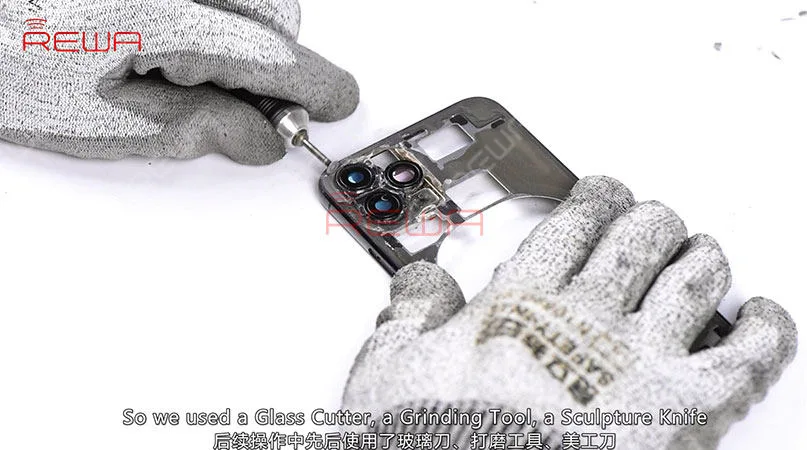
    Nun müssen wir das hintere Glas vom mittleren Rahmen trennen. Die gescannte Rückscheibe lässt sich leicht abtrennen. Das Glas um die Dreilinsenkamera herum muss jedoch weiter bearbeitet werden. Mit unseren üblichen Werkzeugen lässt sich das Glas hier nicht entfernen, daher haben wir einen Glasschneider, ein Schleifwerkzeug, ein Bildhauermesser und eine Schneidzange verwendet, um das Glas um die Dreilinsenkamera herum zu entfernen. Zum Schluss entfernen Sie die Reste des schwarzen Klebers mit der Lasermaschine.
    Nun müssen wir das hintere Glas vom mittleren Rahmen trennen. Die gescannte Rückscheibe lässt sich leicht abtrennen. Das Glas um die Dreilinsenkamera muss jedoch weiter bearbeitet werden. Mit unseren üblichen Werkzeugen lässt sich das Glas hier nicht entfernen, daher haben wir einen Glasschneider, ein Schleifwerkzeug, ein Bildhauermesser und eine Schneidzange verwendet, um das Glas um die Dreilinsenkamera herum zu entfernen. Zum Schluss entfernen Sie die Reste des schwarzen Klebers mit der Lasermaschine.

    Der Kamerahaltering der iPhone 11 Serie ist härter und hat dicke Innenwände, was das Polieren zusätzlich erschwert.

    Außerdem kann das Kameraobjektiv beim Polieren leicht beschädigt werden.

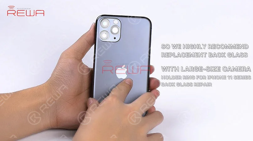
    Daher empfehlen wir für die Reparatur des hinteren Glases der iPhone 11-Serie dringend ein Ersatzglas mit einem großen Kameraloch.
    Der Kamerahaltering der iPhone 11-Serie ist härter und hat dicke Innenwände, was das Polieren zusätzlich erschwert. Inzwischen kann die Kameralinse auch leicht während des Polierens beschädigt werden. So empfehlen wir dringend Ersatz Rückglas mit einer großen Kamera Loch für iPhone 11 Serie Rückglas Reparatur.

    Aufgrund der besonderen Anordnung der drei Kameras des iPhone 11 Pro ist der Raum zwischen den drei Kameras ebenfalls eng, was die Trennung des Rückglases zusätzlich erschwert.

    Daher kann die Laser-Maschine die sicherste und effizienteste Lösung für die iPhone 11 Pro Glasrückseite Reparatur sein.

    Für weitere Details über die Reparatur des hinteren Glases des iPhone 11 Pro, sehen Sie bitte das Video unten. Sie können auch besuchen REWA YouTube-Kanal für weitere Videos zur iPhone 11 Serie.

    REWA LAB wird hart daran arbeiten, eine bessere Lösung für die Reparatur der iPhone 11 Pro Glasrückseite zu finden.

    Die Ersatzteile der iPhone 11 Serie sind auch bald kommen, bleiben Sie bitte abgestimmt auf REWA Online Geschäft.

  • iPhone 11 Pro Rückseite Glasreparatur

    iPhone 11 Pro Rückseite Glasreparatur

    Die Rückkameras der iPhone 11-Serie erhöhen die Schwierigkeit der Reparatur der Rückseite erheblich. REWA LAB hat verschiedene Lösungen ausprobiert (Erhitzen mit der Heißluftpistole, Trennen mit dem Dispergiergerät/Gefrierunterstützung) und wir waren nicht in der Lage, das Glas um die Dreifach-Kamera sicher und effizient zu entfernen. Sehen Sie sich jetzt unser Video zur Reparatur der iPhone 11 Pro Rückseite an und wir hoffen, dass wir Sie damit etwas inspirieren können. Bitte teilen Sie uns Ihre Meinung zu diesem Thema in den Kommentaren unten mit.

    Werkzeuge & Teile, die in diesem Video zur Generalüberholung des iPhone 11 Pro Rückglases verwendet wurden:


  • Turn iPhone 11 Pro Into iPhone 11 Pro Max

    Turn iPhone 11 Pro Into iPhone 11 Pro Max

    Can iPhone 11 Pro possibly be turned into iPhone 11 Pro Max? It is actually theoretically possible. With pins of the two phones’ display connector and touch connector functioning almost the same, we can turn an iPhone 11 Pro into an iPhone 11 Pro Max by changing board ID resistors. Check our video now and find out how we finally made it.

    Warm Tips: This video is made for technique sharing only. For those who have no professional skills, please look before you leap.

    Für das Trennen des iPhone 11 Pro verwendete Werkzeuge & Teile:

  • iPhone 11 Pro Motherboard Separating & Recombination

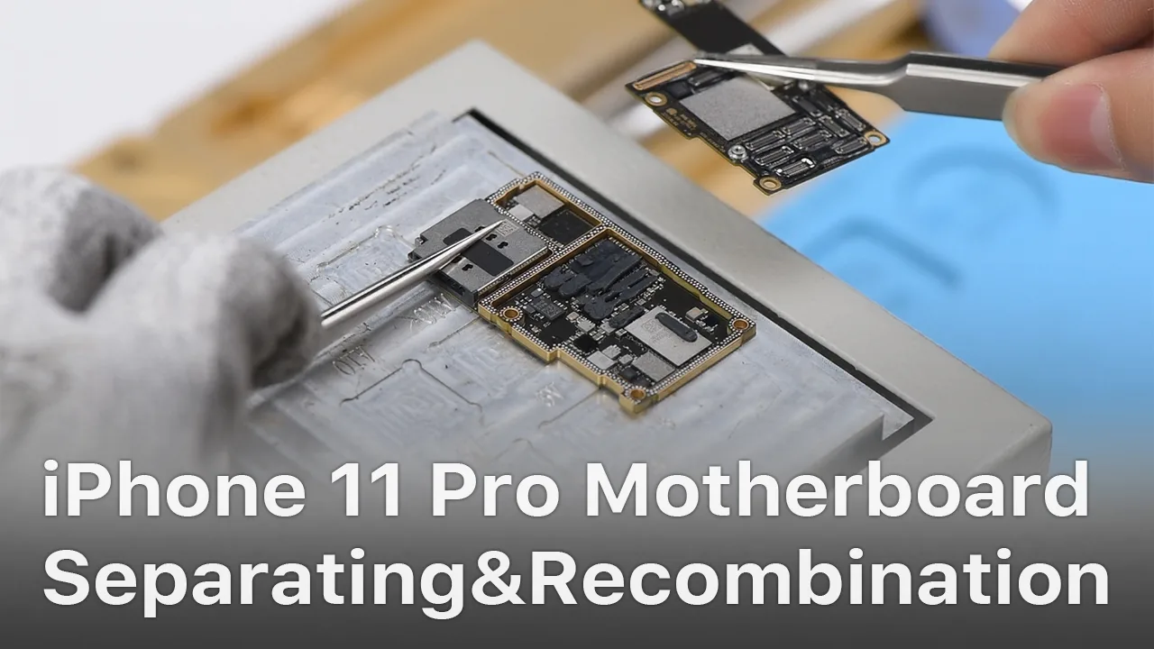
    Trennung und Wiedervereinigung des iPhone 11 Pro Mainboards

    Die neuen iPhone-Serien haben sowohl innen als auch außen beträchtliche Änderungen erfahren. Vor allem beim Motherboard. Wie werden sich diese Änderungen auf die Reparaturbranche auswirken? Wird sie Reparaturen durch Dritte erschweren oder erleichtern? Folgen Sie heute unserem Video zur Trennung und Wiederzusammenfügung des iPhone 11 Pro Motherboards und finden Sie die Antwort selbst.

    Für das Trennen des iPhone 11 Pro verwendete Werkzeuge & Teile: